OPEN ACCESS
This article presents a numerical simulation of the condensation of water vapor with air as the non-condensable gas on an isothermal vertical wall and for inlet mass fraction of the air from 0.05 to 0.5 using the Volume of Fluid (VOF)model of Fluent 6.3 software. The condensation model was used for two-phase, two-dimensional and compressible VOF model and it is suitable for the condensation in presence of additional non-condensable gases on an isothermal vertical plate. All the thermal properties of the water vapor and air were assumed to be functions of temperature and were calculated in user- defined functions (UDF). The source terms including mass source term, energy source term and species source term were also calculated using UDF and hooked to their corresponding conservation equations. The results from the condensation simulation are compared with the experimental results of Dehbi, Uchida and Tagamia from the literature. The condensation simulation results match closely with Dehbi’s experimental correlation, and differ with the curve of Dehbi’s 6%, which show that the simulation model is reliable. The condensation simulation results show that, the surface normal velocity has a prominent contribution in enhancing the convection heat transfer process, the wall shape should be changed to increase the normal velocity component. The results also show that the change of the mass fraction of the non-condensable gas directly influence the thickness of the condensate film, and then affect the local heat transfer coefficient.
Condensate; heat transfer; non-condensable gas; vertical wall; numerical simulation.
The phenomenon of condensation of steam in presence of non-condensable gases occurs in many industrial processes, such as thermal power, nuclear power, air condition, chemical production and waste heat utilization and some heat exchangers. The study on the condensation heat transfer in presence of non-condensable gases has received substantial attention more and more with the great importance given to energy efficiency and security. However, a detailed understanding and capability of predicting it are still lacking. As the research on the heat and mass transfer process in presence of non-condensable gases was largely limited to the experimental method at present, and the conclusions of the experiments vary widely under different experimental conditions, research findings cannot be used extensively. The understanding on the physics of water vapor condensation in presence of non-condensable gases should be enhanced and the techniques to predict the heat and mass transfer involved numerically for industrial applications should be developed.
The influence of non-condensable gases is neglected by the classical Nusselt’s model by various simplifying assumptions [1], so the solution of Nusselt’s problem may now be regarded as some departures from actual situations. Many researchers described the analysis of the heat and mass transfer in situations with steam condensation in presence of non-condensable gases. Colburn and Hougen [2] developed the theory for condensation mass transfer controlled by the mass concentration gradient through the non-condensable gas layer firstly. Since Minkowycz and Sparrow (1966) [3] derived the boundary layer approximations in the 60s, numerical methods have been used in theoretical research more and more. A great convenience was provided to analyze the condensation of vapor mixed with non-condensable gas, however, there is not yet a united recognition on the calculation and simplify. A united theory is not yet formed because of the complexity of the influence of the factors affecting the condensation heat transfer. Condensate film is one of the key points where a total disagreement is found. It is mostly neglected in the previous model. Whitley etc. [4] and Corradini [5] thought by comparison the resistance of the liquid film did not have much effect on the whole thermal resistances when a few non-condensable gases existed. There have been several experiments performed to study condensation of vapor-gas mixture on the isothermal vertical wall [6,7], on a horizontal tube [8,9], in a left-right symmetric internally fined tube [10] and in enclosures [11]. Nevertheless, the mechanistic understanding on this phenomenon is insufficient, further insight is necessary. In addition to the method of experimental research, some theoretical and numerical research are conducted [12]. The equations, in combination with many theoretical models for heat and mass transfer for the gas-vapor mixture, were solved numerically and the predictions were found to compare favorably with available experimental results from the literature [13,14].
Recently, modeling of water vapor condensation in presence of non-condensable gases has been conducted using computational fluid dynamics (CFD) [15]. The advantages of CFD lies in its ability to predict water vapor condensation in comples gemetries and its less assumptions in modeling the mass and heat transfer involved [16,17]. In order to efficiently model the wall condensation in presence of non-condensable gases using CFD, several boundary condition formulations have been proposed in the past for laminar and turbelent flows [18,19,20]. A temperature jump at the liquid-vapor interface cannot be explained reasonably leaving condensate film out of account. The laws of condensation of vapor-gas mixture on the isothermal vertical wall cannot be covered essentially. Inasmuch as such an investigation is concerned with the influence of condensate film on account of vapors with non-condensable gases condensation on isothermal vertical surfaces. We model both the gas mixture region and the liquid film using commercial CFD code FLUENT on the vertical wall.
The main objective of the present study is to develop a condensation model with Fluent 6.3 software that could be used to simulate the performance of condensation heat transfer in presence of a non-condensable gas and to particularly evaluate the influence of the non-condensable gas on distributions of the velocity, temperature, gas concentration, and interface characteristics, as well as the heat transfer coefficient, which is of great significance to engineering design and optimizing in practical condensation heat transfer process.
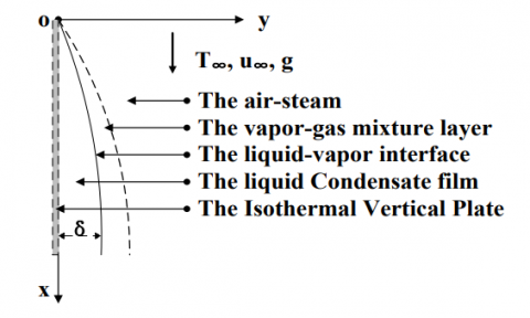
Consideration is given to an isothermal vertical plate situated adjacent to a large body of otherwise vapor. In view of its technical importance, steam was selected as the condensing vapor for the present investigation, with air as the non-condensable gas. When the plate temperature is maintained at a value below the saturation temperature of the vapor, condensation will occur. As shown in Fig.1.
Figure 1. Schematic diagram of condensation of vapor-gas mixture flowing along an isothermal vertical plate
A 2-dimensional model was adopted. The coordinates along (vertically downward) and normal to the plate are x and y, with x=0 coinciding with the leading edge. The corresponding velocity components are u and v. The schematic of the model with the coordinates is shown in Fig. 1. The computational domain, of 0.1m in x direction and around 0.05m in y direction is split into two parts, condensation on the liquid-vapor interface region and condensation on the wall.
2.1 Governing equations
The conservation of mass or continuity can be written as:
$\rho \nabla \cdot U=S_{\mathrm{m}}$ (1)
The equations for momentum conservation is
$\rho U \cdot \nabla U=-\nabla P+\mu \nabla^{2} U+\rho \mathrm{g}$ (2)
The conservation of energy can be written as:
$\rho \cdot \nabla T=\nabla \cdot\left(\mathrm{k} \nabla T-\sum_{\mathrm{i}} h_{\mathrm{i}} \overrightarrow{J_{\mathrm{i}}}\right)+S_{\mathrm{h}}$ (3)
Where $S_{\mathrm{h}}$ is the source term for energy.
$J_{\mathrm{i}}=-\left(\rho D_{\mathrm{i}}+\frac{\mu_{\mathrm{t}}}{S c_{\mathrm{t}}}\right) \nabla W_{\mathrm{i}}-a_{\mathrm{i}} \frac{\nabla T}{T}$ (4)
Where $J_{\mathrm{i}}$ [$m^{2} / s$ ]is a diffusive mass flux owing to concentration and temperature gradients. $a_{i}$ [ $m^{2} / s$ ]is the thermal diffusion factor. $S c_{\mathrm{t}}=0.7$ is turbulent Schmidt number. $\mu_{\mathrm{t}}$ is eddy viscosity. $D_{\mathrm{i}}$ [ $m^{2} / s$ ] is the mass diffusion coefficient of vapor in the mixture, it is given by Equation (5).
$D_{\mathrm{i}}=2.56 \times 10^{-5}\left(\frac{T}{273.15}\right)^{1.5} \cdot \frac{101325}{P_{\mathrm{i}}}$ (5)
The species conservation equation with mass diffusion is
$\rho \nabla(U W)=\nabla J_{\mathrm{i}}+S_{\mathrm{i}}$ (6)
2.2 Condensation on the wall
The grids near rigid wall are checked before the calculation. If the liquid phase volume fraction in the cell is 1, the cell is full of liquid and the condensation and evaporation in the cell no longer starts. If the liquid phase volume fraction in the cell is not 1, the cell is not yet full of liquid. When the saturate temperature corresponding to the partial pressure of the steam in the cell is higher than the wall temperature, the vapor starts to condensate immediately. The energy released by the condensation heats up the temperature of the gas-vapor mixture to the saturation temperature, and then the mass fraction of the vapor is the saturation mass fraction. When the saturate temperature corresponding to the partial pressure of the steam in the cell which is not full of liquid, the condensation is not yet starting and the mass fraction of the vapor remain unchanged. That is
$T_{\mathrm{c}} \geq T_{\mathrm{w}}, W_{\mathrm{i}}=\frac{P_{\mathrm{i}} M_{\mathrm{i}}}{P_{\mathrm{i}} M_{\mathrm{i}}+P_{\mathrm{a}} M_{\mathrm{a}}}$ (7)
$T_{\mathrm{c}} \leq T_{\mathrm{w}},\left.\frac{\partial W_{\mathrm{i}}}{\partial y}\right|_{\mathrm{w}}=0$ (8)
2.3 Source terms
In simulating the condensation in presence of non-condensable gases on the isothermal vertical plate as shown in Fig. 1, various source terms exist at the interface between the condensate film and the vapor gas mixture. These need to be specified during the CFD simulation.
The source term for the total mass and the water-vapor are due to the condensation of water vapor at the interface between the condensate film and the vapor gas mixture is calculated as
$S_{\mathrm{m}}=\dot{m} \frac{A_{\mathrm{w}}}{V_{\mathrm{c}}}$ (9)
Where $A_{\mathrm{w}}\left[m^{2}\right]$ is the condensate surface area in the cell and $V_{\mathrm{c}}\left[m^{3}\right]$ is the cell volume.
The mass flow rate of the condensate film can be deduced from both Fick’s law and the advective mass transfer at the interface, in addition to the mass balance:
$\dot{m}=-\rho D_{\mathrm{i}} \frac{1}{1-W_{\mathrm{i}}} \frac{\partial W_{\mathrm{i}}}{\partial y}$ (10)
If turbulent is taken account, then
$\dot{m}=-\left[\rho D_{\mathrm{i}}+\Gamma_{\mathrm{i}}^{\mathrm{t}}\right] \frac{1}{1-W_{\mathrm{i}}} \frac{\partial W_{\mathrm{i}}}{\partial y}$ (11)
Where, $\Gamma_{\mathrm{i}}^{\mathrm{t}}=\frac{\mu_{\mathrm{t}}}{\sigma_{\mathrm{i}}}$ ,is turbulent diffusivity [$k g / m / s$], $\sigma_{\mathrm{i}}$ is turbulent Prandtl number.
To calculate the condensation rate of the vapor $\dot{m}$ , the gradient of the vapor mass fraction need be calculated. It can be explained as follow:
$\frac{\partial W_{\mathrm{i}}}{\partial y}=\frac{\Delta W_{\mathrm{i}}}{\mathrm{L}}$ (12)
Where, L is the distance of the center of the cell to the wall of the cell.
$\Delta W_{i}=W-W_{i}$ (13)
The source term for energy which corresponds to the source term for mass owing to the condensation of the water vapor is calculated as
$S_{\mathrm{h}}=\dot{m} \frac{A_{\mathrm{w}}}{V_{\mathrm{c}}} h_{\mathrm{fg}}$ (14)
Where, $h_{f g}[\mathrm{J} / \mathrm{kg}]$ is the latent heat released by the water vapor at the interface temperature and it is given by
$h_{f g}=(2500.9-2.365 t) \times 10^{3}$ (15)
Where t [℃] is centigrade.
The source term for species is equal to the source term for mass, and it is written as
$S_{\mathrm{i}}=S_{\mathrm{m}}$ (16)
All the thermophysical properties for the air-steam mixture used in the calculations come from ref.[12].
Two-dimensional steady state analyses are carried out to simulate the condensation of air-steam mixture flowing on an isotherm vertical wall. Volume of fluid(VOF) [21] model is used for simulation, in which Fluent 6.3 software is used for the simulation. The condensation of air-steam mixture on the isotherm vertical wall is modeled using the condensation model above and is embedded in the Fluent code as “User Defined Function”. The steam is treated as a compressible fluid using the ideal gas law for calculating its density. The values of viscosity, thermal conductivity and specific heat capacity of steam are taken from fluent database and are assumed constant during the simulation. The water vapor and air mixture was introduced at the inlet with a given mass flow rate, temperature and mass fraction of the water vapor (or the air). All the thermal properties of the water vapor and air were assumed to be functions of temperature and were calculated in UDF. The source terms mentioned above were also calculated using UDF and hooked to their corresponding conservation equations. Second order upwind schemes are used for the discretization of convective terms in all solved equations. Turbulences is modeled by realizable $k-\varepsilon$ model with enhanced wall treatment.
Mesh independence was carried out to make sure that the simulation results were indepentent of numerical grids, and then mesh with 30×60 cells was used in this simulation respectively in x and y directions for all subsequent simulations. Since condensation occurs at the interface, the mesh is refined near the walls. The thickness of the wall-adjacent cell wall is 0.2mm. Simple coupled-implicit solver is used to solve the non-linear governing equations. The algebraic multigrid solver is used which performs calculations on finer mesh and no coarse meshes have to be constructed or stored, and no fluxes or source terms need to be evaluated on the coarse levels.
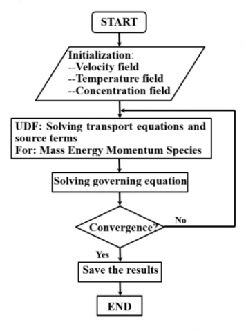
The vapor-gas inlet is selected as the velocity inlet boundary and the outlet is selected as the pressure outlet boundary, while the wall is taken as isotherm wall boundary. The forth side is selected as the symmetry boundary. The geometry and mesh are generated in gambit 2.2.30 software. The solver used was pressure based and the flow is assumed to be steady. User-defined functions (UDFs) were written for all the source terms, boundary conditions as given in Table 1 and the properties of the fluids and were called at each iteration. A schematic diagram of the solution procedures is provided in Fig. 2.
Table 1. Boundary values used in CFD simulation
|
Inlet pressure of the vapor-gas mixture/ (Pa) |
101325 |
|
Inlet velocity of the vapor-gas mixture/(m/s) |
1 |
|
Inlet temperature of the vapor-gas mixture/( K) |
373.15 |
|
Inlet Mass fraction of air/(%) |
5-50 |
|
Temperature of the plate/ (K) |
303 |
|
The height of the plate/(m) |
0.1 |
|
The horizontal distance to the plate/(m) |
0.05 |
Figure 2. Schematic diagram of the solution procedures
In this work the air-steam mixture condensation is studied both experimentally and computationally to validate the simulation. The present simulation is compared with the experimental results to study the characteristics of condensation in presence of non-condensable gas.
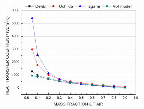
Figure 3. Average heat transfer coefficient as a function
of inlet air mass fraction—comparision of the present
model and various correlations
The results from the condensation simulation agree well with the data from the experimental results of Dehbi [22], Uchida [23] and Tagamia [24] from the literature for the condensation of water vapor with air as the non-condensable gas on an isothermal vertical wall. The condensation simulation results match closely with Dehbi’s experimental correlation, and differ with the curve of Dehbi’s 6%, as shown in Fig.3, which show that the simulation model is reliable.
Dehbi’ experimental correlation:
$h=\frac{l^{0.05}\left[(3.7+28.7 P)-(2438+458.3 P) \log \mathrm{W}_{\mathrm{a}}\right]}{\left(T_{\mathrm{b}}-T_{\mathrm{w}}\right)^{0.25}}$ (17)
where,$0.15 \leq P \leq 0.45 M P a$ ; $0.3 \mathrm{m}<l<3.5 \mathrm{m}$ ; $10 \leq\left(T_{\mathrm{b}}-T_{\mathrm{w}}\right) \leq 50 \mathrm{K}$ ,with non-condensable gases such as air and helium.
Uchida’ experimental correlation:
$h=380\left(\frac{W_{\mathrm{a}}}{1-W_{\mathrm{a}}}\right)^{-0.7}$ (18)
Tagami’ experimental correlation:
$h=11.4+284 \frac{1-W_{\mathrm{a}}}{W_{\mathrm{a}}}$ (19)
5.1 Velocity distribution
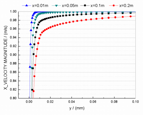
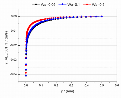
Fig.4 shows the tangential and normal velocity distribution under the conditions of $T_{\mathrm{w}}=330 \mathrm{K}$ , $u=1 \mathrm{m} / \mathrm{s}$ , $W_{\mathrm{a}}=0.05$. It can be seen that the velocity in x direction can reach close to the mainstream speed at the very small distance to the wall. For example, when y=0.01mm, that is the distance to the wall is 0.01mm, the x velocity changed from 1m/s to 0.94m/s, which shows the velocity in x direction (that is tangential velocity) is decreasing with the condensation of the steam, as shown in fig.4(a). It can be seen that there is a normal velocity close to the wall, and the closer to the wall the stronger is the velocity in fig. 4(b). Because concentration gradient is generated with the continual condensation of water vapor, and the advection and sucking effects of water vapor condensation make contributions to the normal velocity, especially at the phase interface.
(a) Tangential velocity distribution
(b) Nomal velocity distribution
Figure 4. Velocity profile as a function of vertical distance along the wall
$\left(T_{\mathrm{w}}=330 \mathrm{K}, u=1 \mathrm{m} / \mathrm{s}, W_{\mathrm{a}}=0.05\right)$
5.2 Concentration distribution
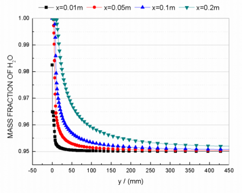
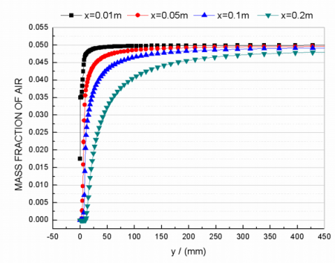
When the inlet velocity is 1m/s, the temperature of the wall is 330K and the air-steam mixture flow along the wall from up to down, the mass fraction of air and water distribution with the variation of normal distance to the wall are shown in fig.5. The mass fraction of air is decreasing along the direction of the flow of air-steam mixture at the same distance to the wall. With the condensation, air-steam mixtures move to the wall, and condense to form the condensate film, so the mass fraction of air is from 0 to 0.05 with the increase of the normal distance to the wall.
(a) Non-condensable gas mass fraction profile
(b) steam mass fraction distribution
Figure 5.Non-condensable gas and steam mass fraction profile as a function of vertical distance along the wall
$\left(T_{\mathrm{w}}=330 \mathrm{K}, u=1 \mathrm{m} / \mathrm{s}, W_{\mathrm{a}}=0.05\right)$
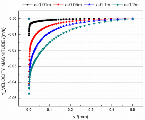
Figure 6. Nomal velocity profile of steam as a function of vertical distance at
$x=0.05 m\left(T_{\mathrm{w}}=330 \mathrm{K}, u=1 \mathrm{m} / \mathrm{s}, W_{\mathrm{a}}=0.1\right)$
It can be seen in fig.6 that the normal velocity distribution of the air-steam mixture as a function of the mass fraction of air and the vertical distance to the wall at the height of x=0.05m. With the increase of the vertical distance to the wall, the normal velocity approaches from -0.04 to 0; at the same distance to the wall (for example y=0.1mm), the higher is the concentration of the air, the smaller is the absolute value of the normal velocity. Because the concentration of the air is higher, the concentration difference because of the condensation of the steam is smaller, the driving force of the condensation is reduced, and then the normal velocity is smaller.
Figure 7. Steam mass fraction contour
$\left(T_{\mathrm{w}}=330 \mathrm{K}, \boldsymbol{u}=1 \mathrm{m} / \mathrm{s}, W_{\mathrm{a}}=0.1\right)$
It can be seen in fig.7 that the condensate liguid film become thicker along the flow direction. At the same distance to the wall, the concentration of the water steam start rising from top to bottom, that is , along the flow direction.
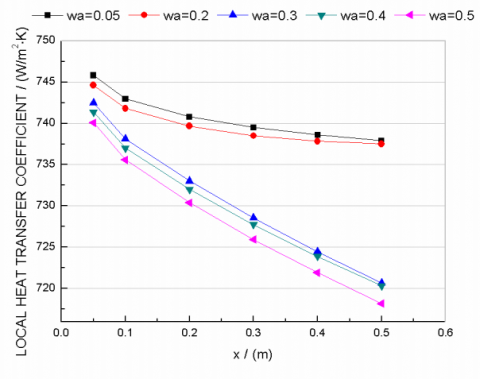
Figure 8. Local heat transfer coefficient along the wall
Fig.8 shows condensation heat transfer coefficients of the air-steam mixture of different mass fraction along the direction of the flow of mixture. The condensate film becomes thicker, so the heat resistance of condensate film is more, the mass fraction of the steam increases, and the driving force of the condensation is reduced, which weaken the condensate heat transfer.
The condensation of water vapor in presence of non-condensable gas on an isotherm vertical wall has been studied using CFD simulation. The effect of the presence of a non-condensable gas on the isotherm wall is studied both experimentally and numerically to validate the simulate model of VOF. The study includes:
(1) The CFD simulation results have been compared with the experimental results of Dehbi, Uchida, Tagamia for the water vapor and air mixture. It is found that the CFD simulation results in general are align with the measured quantities of Dehbi.
(2) The simulation results show that the surface normal velocity has a prominent contribution in enhancing the convection heat transfer process, the wall shape should be changed to increase the normal velocity component.
(3) The results also show that the change of the mass fraction of the non-condensable gas directly influence the thickness of the condensate film, and then affect the local heat transfer coefficient.
|
$A$ |
surface area [$m^{2}$] |
|
$a$ |
thermal diffusion factor [$m^{2} / s$] |
|
$c_{p}$ |
isobaric heat capacity [$J / \mathrm{kg} / \mathrm{K}$] |
|
$D$ |
diffusion coefficient [$m^{2} / s$] |
|
$h$ |
heat transfer coefficient [$W / m^{2} / K$] |
|
$h_{f g}$ |
latent heat [$\mathrm{J} / \mathrm{kg}$] |
|
$J$ |
diffusive mass flux [$m^{2} / s$] |
|
$k$ |
thermal conductivity [$W / m / K$] |
|
$L$ |
distance of the center of the cell to the wall of the cell [$m$] |
|
$l$ |
the length of the wall in flow direction[$m$] |
|
$M$ |
molecular weight [$k g / m o l$] |
|
$\dot{m}$ |
condensate mass flow rate [$\mathrm{kg} / \mathrm{s}$] |
|
$P$ |
pressure [$P a$] |
|
$S_{h}$ |
source term for enthalpy [$W / m^{3}$] |
|
$S_{i}$ |
source term for species [$k g / m^{3} / s$] |
|
$S_{m}$ |
source term for mass [$k g / m^{3} / s$] |
|
$T$ |
temperature [$K$] |
|
$U$ |
velocity vector [$m / s$] |
|
$u$ |
velocity in x-coordinate direction [$m / s$] |
|
$v$ |
velocity in y-coordinate direction [$m / s$] |
|
$W$ |
mass fraction |
|
Greek symbols |
|
|
$\mu$ |
viscosity [$\mathrm{kg} / \mathrm{m} / \mathrm{s}$] |
|
$\rho$ |
density [$k g / m^{3}$] |
|
Subscripts |
|
|
$a$ |
air |
|
$c$ |
cell |
|
$i$ |
species index |
|
$m$ |
mixture |
|
$t$ |
turbulent |
|
$v$ |
vapor |
|
$w$ |
wall |
1. W. Nusselt, The surface condensation of water vapor(in German), Z. Ver. Dt. Ing. vol. 60, pp.541-546, 596-575, 1916.
2. A.P. Colburn, O.A. Hougen, Design of cooler condensers for mixtures of vapors with noncondensing gases, Industrial and Engineering Chemistry, vol. 26, pp. 1178–1182, 1934
3. Minkowycz W J, Sparrow E M. Condensation heat transfer in the presence of noncondensables, interfacial resistance, superheating, variable properties and diffusion. International Journal of Heat and Mass Transfer, vol. 9, pp.1125-1144, 1966.
4. Whitley R H, Chan C K, Okrent D. On the analysis of containment heat transfer following a LOCA. Annals of Nuclear Energy, vol. 3, pp.515-525, 1976.
5. Corradini M L. Turbulent condensation on a cold wall in the presence of a noncondensable gas. Nucl. Technol. (United States), vol. 64, 1984.
6. D. Y. Shang and B.X. Wang, An extended study on steady-state laminare film condensation of a superheated vapour on an isothermal vertical plate, International Journal of Heat and Mass Transfer, vol.40, pp.931-941, 1997.
7. Li Cheng, Li Junming, Experimental study of the moist air condensation across a vertical cold wall. Journal of engineering thermophysics. vol.32, pp.871-874, 2011.
8. Tang,G.H.,Hu H. W., Zhuang, Z. N., Tao W. Q.,Film condensation heat transfer on a horizontal tube in presence of a noncondensable gas. Applied Thermal Engineering, vol.36, pp.414-425, 2012.
9. Yin Ming,Chen Jiabin,Ma Xuehu,Li Songping. Condensation of low-pressure vapor in horizontal tube. Journal of Chemical Industry and Engineering (china), vol.54: pp.913-917, 2003.
10. Wang Yungang, Zhao qinxin,Zhou Qulan, Kang Zijin, Tao wenquan, Experimental and numerical studies on actual fuel gas condensation heat transfer in a left-right symmetric internally fined tube. International Journal of Heat and Mass Transfer, vol. 64, pp.10-20, 2013.
11. Costa V. A. F., Transient natural convection in enclosures filled with humid air. International Journal of Heat and Mass Transfer, vol. 55(21-22), pp.5479- 5494, 2012.
12. Li Cheng, Li Junming. Laminar Forced Convection Heat and Mass Transfer of Humid Air across a Vertical Plate with Condensation, Chinese Journal of Chemical Engineering, vol.19, pp. 944-954, 2011.
13. Li Xiaowei, He Xinxin, He Shuyan. Numerical simulation of the heat and mass transfer process of convective condensation with non-condensable gas, Journal of Engineering Thermophysics, (02), pp.302- 307, 2013.
14. Ganguli A.,Patel A. G., Macheshwari N. K. Theoretical modeling of condensation of steam outside different vertical geometries(tube, flat plates) in the presence of noncondensable gases like air and helium. Nuclear Engineering and Design, vol. 238, pp.2328-2340, 2008.
15. Jun-De Li. CFD simulation of water vapour condensation in the presence of non-condensable gas in vertical cylindrical condensers, International Journal of Heat and Mass Transfer, vol. 57, pp.708-721, 2013.
16. Chui Yongzhang, Tian Maocheng, et al., Three Dimensional Numerical Simulation of Convection- Condensation of Vapor with High Concentration Air in Tube with Inserts, Chinese Journal of Chemical Engineering, vol. 20, pp.686-692, 2012.
17. Kafoussias. N. G and Xenos, Numerical investigation of two-dimensional turbulent boundary-layer compressible flow with adverse pressure gradient and heat and mass transfer. Acta Mechanica, vol. 141, pp.201-223, 2000.
18. Karkoszka, K., Anglart, H., 2008. Multidimensional effects in laminar filmwise condensation of water vapour in binary and ternary mixtures with nonvondensable gases. Nucl. Eng. Des. Vol, 238, pp: 1373-1381, 2008.
19. Kelm, S., Cmbination of a Building Condenser with H2-Recombiner Elements in Light Water Reachtore. Schriften des Forschungszentrums Jülich , pp. 56, 2010.
20. G.Zschaeck, T. Frank, A.D.Burns, CFD modelling and validation of wall condensation in the prsence of con- condensable gases. Nuclear Engineering and Design, Vol. 279, pp: 137-146, 2014.
21. Fluent Inc., Fluent 6.3 User’s Guide. Fluent Inc., 2006.
22. Tagami T. Interim report on safety assessments and facilities establishment project for June. Japanese At. Energy Res. Agency, No.1, 1965.
23. Dehbi A A, Analytical and experimental investigation of the effects of noncondensable gases on steam condensation under turbulent natural convection conditions, Ph.D. thesis, Massachusetts Institute of Technology. Department of Nuclear Engineering, 1990.
24. Uchida H, Oyama A, Togo Y. Evaluation of post- incident cooling systems of light water power reactors. Rept. Tokyo Univ., 1964.