Murtada A. Ismael*![]() | Yahyia M. Hameed
| Yahyia M. Hameed![]()
© 2023 IIETA. This article is published by IIETA and is licensed under the CC BY 4.0 license (http://creativecommons.org/licenses/by/4.0/).
OPEN ACCESS
Voided concrete slabs have emerged as a good alternative to solid slabs in many applications due to their excellent advantages. Although these slabs have a good thermal insulation ability, they have a disadvantage represented by their low fire resistance, this defect may affect the structural performance of bubbled slabs subjected to elevated temperatures more than that of the solid slabs. Since there is a considerable lack of knowledge about this effect, this paper presents an empirical exploration on the impact of exposure to elevated temperature on the structural performance of voided reinforced concrete two-way slabs. The empirical plan includes construing and testing eight voided reinforced SCC slabs subdivided into two groups to study the effect of the exposure to different elevated temperature degrees and the exposure period to the elevated temperature. The outcomes reveal that increasing the temperature from 100 to 400℃ makes the first crack of the voided slabs decreases from 9.4% to 35.2%, the ultimate load decreases by 10.7% to 38.2%, and the ductility ratio decreases from 7.1% to 28.6% respectively, while increasing the exposure period from 1hr to 4hrs. leads to decreasing the cracking load from 35.2% to 62.8%, the ultimate load from 38.2% to 63.2%, and the ductility ratio decreases from 28.6% to 38.1% respectively. Also, the results show that it is necessary to avoid using this type of slab in buildings exposed to high temperatures exceeding 100℃, significantly when the exposure period exceeds one hour.
concrete, elevated-temperature, heating, slab, structural, voided
Exposure to extreme temperatures is one of the major dangers confronting concrete structures. Many reasons can lead to exposing structural concrete members to elevated temperatures. Fire accidentals are one of the most common causes. Also, many industrial installations such as furnaces, industrial chimneys, floors below boilers, and kilns, in which the concrete is exposed to sustained elevated temperatures [1, 2]. Slabs are the most structural members affected by elevated temperatures due to the large area of their surface that is exposed to heat relative to its thickness [3, 4].
On the other hand, the voided concrete slab or bubbled concrete slab, which is a kind of lightweight concrete slab, emerged in recent years as a good alternative to the solid slabs in many applications due to its excellent advantages represented by using a smaller amount of concrete compared to a solid slab of the same size, since the plastic balls which are used to create air voids can decrease the deadweight up to 35%, maintaining the structural performance is approximately similar to that of the solid slab, this leads to reducing cost, obtaining large spans, reducing the time required for construction, and helping in the sustainability process as it reduces the amount of consumed materials. Although these slabs have a good thermal insulation ability, they have a disadvantage represented by their low fire resistance [5-9]. This defect makes us believe that the structural performance of voided concrete slabs is more affected by the elevated temperature than that of solid concrete slabs. This requires studying the structural performance of this type of slab when exposed to high temperatures to evaluate this effect.
A number of studies dealing with the influence of heating and firing on the performance of two-way slabs were presented. However, Vecchio et al. [10] investigated the impact of the amount and orientation of the in-plane reinforcement of reinforced concrete (RC) slabs subjected to thermal loads. The results demonstrated that the slabs exhibited significant cracking and stressing stages due to restrained thermal deformations. Sangluaia et al. [11] used two stages of finite element analysis to determine the thermal effect on structural RC slab. In the first stage, the temperature distribution across the thickness for the period of burning was found, in the second stage, the analytical investigation was achieved. They found that slab displacement increases with the increase of the slab width and there was a reduction in the slab displacement with increasing reinforcement ratio and slab thickness. Yang et al. [12] used two large-size furnaces to conduct tests on slabs sustained by composite beams, the results demonstrated that the performance of these slabs depended greatly on the type of slab restriction. Levesque [13] examined the influence of slab thickness and type of aggregate on the response of RC slabs subjected to fire, in that study a simplified design tool was presented that evaluates the performance of RC slabs exposed to fires. Farhan [14] investigated the effect of steel fiber ratio on the fire performance of two-way slabs made of normal, high-strength, and light-weight concrete under 25℃, 400℃, and 600℃, their outcomes revealed that as the steel fiber ratio increased, the punching shear strength of slabs exposed to various elevated temperature increased and the presence of fibers raised the cracking load and made the deflection less than that of the slab without fibers. Riad and Shoeib [15] presented a study about the fire performance of two-way flat slabs made of lightweight polystyrene foam concrete. The study results showed that the crack load and ultimate load of the slab with foam concrete were reduced compared with that of the normal concrete. Allam et al. [16] performed a finite difference analysis to study the behavior of one-way reinforced concrete slabs subjected to fire. The outcomes showed that raising the cover thickness and the existence of plaster led to improving the ultimate danger period and the live load variation had no effect on such period. Abdullah and Al-Khazraji [17] investigated the effect of laced steel reinforcement ratio on the fire response of laced RC one-way slabs made of high strength under the effect of fire flame. The outcomes indicated that increasing the ratio of laced reinforcement made the ultimate load and ductility increase, the deflection corresponding to ultimate and service loads were increased.
Abdul Rahman and Tause [18], explored the influence of high temperatures on SCC two-way slab specimens under static and impact loads using fast and gradually slab cooling after heating. It was found that the increase in the temperature has a negative effect on the ultimate strength and ductility under static load. While the impact loads caused decreeing in the Impact resistance and increased the time and ratio damping under the two cooling methods. Waryosh and Hashim [19] focused their study on the impact of concrete burning on the spalling of concrete cover slab concrete of bubbled slabs, as well as the slab deflection, they concluded that the spalling occurs as the bubbled slab expose to 300℃ and 400℃ and deflection increase with increase fire flame temperature and duration. Jawad and Waryosh [20, 21] explored punching shear strength of geopolymer bubbled slab subjected to exposed to fire flame. They found a reduction in the ultimate load of geopolymer more than in normal concrete with negligible spalling and increasing the punching shear stress with increase the fiber ratio. Miller et al. [22] presented a numerical thermal analysis on the concrete slab with spheric hollows, and their outcomes revealed that the spheric hollows had no significant effect on bending strength. Alawsi et al. [23] found a drop in strength and mechanical features of slabs with voided concrete as subjected to uniformly distributed loads and extreme fire flame.
In general, it can be noticed throughout the previous studies that there is a considerable lack of knowledge about the effect of the elevated temperature on the voided RC slabs and most of the scientific efforts were devoted to the solid concrete slabs. Therefore, this paper aims to investigate experimentally the impact of the exposure to different elevated temperature degrees and the exposure period to the elevated temperature on the structural performance represented by cracking load, ultimate load, deflection, load-deflection behavior, ductility, and crack development with loading, of voided reinforced self-compacting concrete (SCC) slabs by testing eight voided slab specimens and compare the results with that of a reference slab does not expose to elevated temperature.
2.1 Specimen details
The experimental scheme of this investigation includes testing eight voided slabs constructed using SCC with voids were created using plastic balls. The slab specimens are subdivided into two groups. The first group consists of four specimens to study the effect of the exposure to different elevated temperature (100, 200, 300, and 400℃). The second group also consists of four specimens to study the effect of exposure period (1, 2, 3, and 4 hrs.) to the elevated temperature (400℃) on the structural performance of voided reinforced SCC slabs.
Table 1. Parameters and details of voided SCC slab specimens
|
Group No. |
Parameter |
Slab code |
Temperature degree (℃) |
Period Exposure (hrs.) |
|
--- |
--- |
S1 |
21* |
- |
|
One |
Temperature degree |
S2 |
100 |
1 |
|
S3 |
200 |
1 |
||
|
S4 |
300 |
1 |
||
|
S5 |
400 |
1 |
||
|
Two |
Exposure period |
S5 |
400 |
1 |
|
S6 |
400 |
2 |
||
|
S7 |
400 |
3 |
||
|
S8 |
400 |
4 |
*Laboratory temperature
Figure 1. Dimensions of the slab, steel reinforcement grids and distribution of plastic balls within the slab
The results of the two groups were compared with a reference slab specimen that is not exposed to high temperatures as tabulated in Table 1. The slabs have an identical dimension (500mm length, 500mm width, and 80mm thickness). Figure 1 shows Schematic sections in the mid-depth and mid-span in the slab illustrate dimensions of the slab, steel reinforcement grids, the distances between steel reinforcement rebars the distribution of plastic balls within the slab.
2.2 Concrete
The type of concrete employed in this exploration is SCC, which was developed according the European specification of SCC (EFNARC) [24], SCC comprises the following components: Cement of kind I that satisfies IQS No.5/1984 [25], fine and coarse aggregate satisfy IQS No.45/1984 [26], limestone powder satisfies (EFNARC) [24], Superplasticizer satisfies ASTM C494 [27] and Water. Table 2 tabulates the components of SCC and their quantities.
Table 2. SCC components and their quantities per m3
|
Cement (kg) |
Sand (kg) |
Gravel (kg) |
Lime-stone (kg) |
Super-plasticizer (liter) |
Water (liter) |
|
400 |
821 |
767 |
132 |
2.2 |
192 |
In order to confirm that the concrete employed in this study is SCC, the main tests of SCC (Slump, T500, V-funnel, and L-box) reported by EFNARC for SCC [24] were carried out on the fresh concrete. The outcomes of these tests proved that the concrete of this exploration is SCC as listed in Table 3.
Table 3. Outcomes of standard SCC test
|
Mix |
Slump flow (mm) |
T500 (sec) |
V-funnel (sec) |
L-box (H2/H1) |
|
SCC |
688 |
4 |
10 |
0.95 |
|
EFNARC limits [30] |
650-800 |
2-5 |
6-12 |
0.8-1 |
H1: Fresh concrete depth at the end of horizontal prat of the L-box
H2: Fresh concrete depth in the vertical part of the L-box
2.3 Steel reinforcement grids
All the slabs are reinforced by 16 deformed rebars of 4mm diameter in each direction of the slabs as top and bottom reinforcement steel grids. The reinforcement steel bars are arranged so that the distance between every two bars holding the plastic balls is 2.5cm from center to center of the bars, While the distance between each bar of a row of balls to the next bar in the next row of balls is 3 cm from center to center of the bars as shown in Figure 1. The rebars have a yield stress of 388 MPa and were tested according to ASTM A 615/A 615M [28].
2.4 Balls
Plastic spherical balls of 40mm diameter were used in this work to create the voids in the slabs. These balls are strong enough to support safely the applied loads in the phases before and during concrete casting. The plastic balls were fixed using the two reinforcement steel grids from the top and bottom. Figures 1 illustrate the distribution of balls in the slab.
2.5 Casting of concrete
The SCC components were mixed using a mixer has a volume of 0.07 m3 according to the EFNARC specifications [24], the fresh SCC mixture was added to the molds of the slabs that contained the reinforcement steel grids and the plastic balls. With each slab casting, three concrete cylinders were poured of dimensions 300mm in height and 150mm in diameter, and the average of each three concrete cylinders was considered to find the concrete compressive strength of each slab established on ASTM C39/C39M [29].
2.6 Curing
After completing the process of pouring the concrete into the molds of the slabs and cylinders, they were covered with nylon tightly to prevent water loss at a temperature ranging from 16℃ to 28℃, and relative humidity of 32% to 43% for 24 hrs., to give the concrete enough time to reach the state of final setting and gain sufficient hardening, after that, the concrete slabs and cylinders were taken out from the molds and immersed in a water tank for the age of 28 days at a laboratory temperature which varies from 13℃ to 29℃ and relative humidity between 28% to 52% according to ASTM C 192/C 192M [30].
2.7 Slab heating
At 28 days after casting and curing, the slabs and the concrete cylinders were taken out from the curing water and left to dry. Then, they were exposed to the elevated temperature degree and for a period according to the experimental program using an electric oven model 2012 manufactured by jet materials ltd (UK-based company). shown in Figure 2. After the heating process, the heated slabs were taken out of the oven and left to cool gradually for one day at the laboratory temperature which was 21℃ at the testing.
Figure 2. Heating the voided slabs
2.8 Test setup
The slabs were tested as simply supported. A flexural hydraulic machine of 2000 kN model 2011 manufactured by jet materials ltd (UK-based company) was employed to apply a static load on the slabs by a circular steel column of diameter (100mm) placed at the center of the upper slab face. This position of the applied load represents the critical region that causes maximum bending moment and maximum deflection which are considered in the analysis and design of slabs. The circular section was chosen to ensure that the loads are distributed uniformly from the steel column to the slab specimens, since the square or rectangular cross-section leads to a concentration of stresses at the corners, causing irregularity of the stress distribution. As for the size of the steel column, it was selected to allow the slab specimens to fail by either punching shear or flexure according to the specimen response to know the effect of high temperatures on the failure mode. Since the smaller sizes will make the failure limited by one type of failure, which is the usually punching shear, as the slab of this research is of a flat plate type.
The load was applied with a constant loading rate of 0.5kN/sec up to failure. The loading rate is within static loading and this rate simulate the realistic loads as rapid loading within static loading makes the concrete resists higher the load better and the modulus of elasticity become higher for fast loading [31]. The vertical deflection of the center bottom slab face was measured using one electrical linear variable differential transformer (LVDT) that has a range of 50mm and an accuracy of 0.001mm. Figure 3 shows the test setup and the mechanism of the load application.
Figure 3. One of the voided slab specimens under testing
3.1 Slab crack patterns
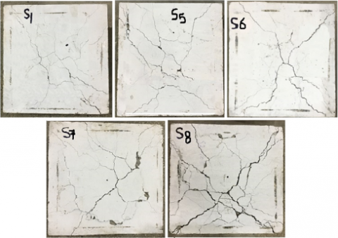
Figures 4 and 5 show the cracking modes at the failure of the tested slabs. The initial crack in all the slabs formed at the center of the bottom slab face at a load range between 13 kN to 35 kN. For the reference slab S1, increasing the load after the first crack made the initial cracks widen and extend diagonally to the corners and vertically towards the top face until failure occurred. For the first group, it was observed that the increase in the temperature from 100℃ to 400℃ made the slab failure tends towards the brittleness, and the cracks diffused and grew faster and wider than that of the reference slab. This behavior became more clearer in the second group, in which the exposure period increased from 1hr to 4hrs. at the temperature of 400℃, especially for the slabs that were exposed for a period of 3 and 4 hrs., as these slabs suffered from crushes upon failure and their failure was sudden. Also, Figures 4 and 5 reveal that both the increase in temperature and the increase in the period of exposure to high temperature make the cracks wider and deeper at failure, also these increases do not affect the failure mode as all the examined slabs failed with flexure mode.
Figure 4. Effect of exposure to different temperatures on crack patterns at failure
Figure 5. Effect of exposure period to elevated temperature on crack patterns at failure
3.2 Cracking load and ultimate strength
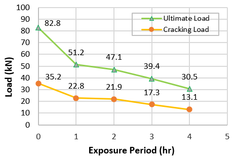
Table 4 illustrates the cracking load and ultimate load of the slabs obtained directly from the experimental tests that were carried out as shown in Figure 3. Generally, the table reveals that increasing the temperature to which the voided SCC slabs are exposed and increasing the period of exposure to elevated temperature have a slightly greater effect on the ultimate strength than that on the cracking load. However, increasing the temperature to which the slabs are exposed from 100℃ to 200℃, 300℃ and 400℃ makes the cracking load decrease by 9.4%, 16.8%, 27.3%, and 35.2%, and the ultimate strength decreases by 10.7%, 19.3%, 28.4%, and 38.2%. The explanation for the decreases in the cracking load and the ultimate strength can be divided into three reasons: The first reason relates to the effect of high temperature on concrete. According to Neville [32], exposing concrete to high temperatures causes dehydration of the hydration products of cement resulting in loss of the chemically combined water from the cement paste, which in turn leads to weak bonding of cement paste with coarse aggregate and reduction the strength of concrete. This effect is evident from the decrease in concrete compressive strength (fc'), which is an indicator of a decrease in the values of other concrete mechanical properties. However, increasing the temperature to which the slabs are exposed from 100℃ to 200℃, 300℃ and 400℃ makes the compressive strength decrease with percentages of 9.4%, 18.8%, 28.1%, and 34.4% respectively. This effect is initially limited to the faces and the outer layers of the slab, and it increases with increasing the temperature from 100℃ to 400℃. The second reason is related to the effect of elevated temperature on steel reinforcement, as a number of studies found that the mechanical properties of steel rebars exhibit a reduction with elevated temperatures [33-37]. The third reason is represented by the bonding strength between concrete and steel reinforcement which decreases with increasing temperature [37-40]. It is certain that the second and third reason is related to the penetration of heat into the areas of the presence of reinforcement steel. On the other hand, increasing the exposure period from 1hr to 2hrs., 3hrs., and 4hrs. leads to decreasing the cracking load by 35.2%, 37.8%, 50.9%, and 62.8%, and ultimate load by about 38.2%, 43.1%, 52.4%, and 63.2%. The large decreases due to increasing period exposure can be explained by the extent the exposure period to elevated temperature makes the heat penetrate the inner layers of the voided SCC slab, leading to a deepening of the effect of dehydration of the cement hydration products, therefore, the compressive strength decreases with percentages 34.4%,43.8%,50.0 ad 56.3% respectively, as well as the effects of high temperature in weakening the mechanical properties of steel reinforcement rebar and the bonding between rebar and concrete. Figures 6 and 7 show the relationship between the exposure to different temperature degrees and exposure period to elevated temperature on cracking load and ultimate strength respectively. These figures reveal that the relationship of temperature change with the cracking load and ultimate strength is approximately linear, while the relationship of the exposure period to high temperatures with the cracking and the ultimate strength begins with a large slope between in the first hour and then tends to be linear after the first hour.
Table 4. The impact of the exposure to elevated temperature and exposure period on cracking load and ultimate load of voided slabs
|
Slab code |
D1 (°C) |
T2 (hrs.) |
fc'3 (MPa) |
Pcr4 (kN) |
Decreasing percentage (%) |
Pult5 (kN) |
Decreasing percentage (%) |
|
S1 |
21 |
- |
32 |
35.2 |
- |
82.8 |
- |
|
S2 |
100 |
1 |
29 |
31.9 |
9.4 |
73.9 |
10.7 |
|
S3 |
200 |
1 |
26 |
29.3 |
16.8 |
66.8 |
19.3 |
|
S4 |
300 |
1 |
23 |
25.6 |
27.3 |
59.3 |
28.4 |
|
S5 |
400 |
1 |
21 |
22.8 |
35.2 |
51.2 |
38.2 |
|
S5 |
400 |
1 |
21 |
22.8 |
35.2 |
51.2 |
38.2 |
|
S6 |
400 |
2 |
18 |
21.9 |
37.8 |
47.1 |
43.1 |
|
S7 |
400 |
3 |
16 |
17.3 |
50.9 |
39.4 |
52.4 |
|
S8 |
400 |
4 |
14 |
13.1 |
62.8 |
30.5 |
63.2 |
1 D: Degree of Temperature, 2 T: Period exposure, 3 fc': concrete compressive strength of slab, 4 Pcr: Cracking load, 5 Pult: Ultimate load
Also, it can be noted from these figures that the change in the ultimate strength is steeper than the change in the cracking load. This behavior can be explained by the fact that the cracking load is the load in which the stresses in the concrete reach the value of its tensile strength, and these stresses are concentrated in a limited area in the slab (the middle area in the lower face of the slabs as the applied load on the slab leads to positive bending moment causing compression zone in the upper part of the slab and tension zone in the lower part). While the ultimate strength, represents the load in which the stresses in most of the tensile zone have reached or exceeded the tensile strength value, and the stress in steel reinforcement exceeds the yield stress and this area certainly be large compared to the area where the first crack occurs. Therefore, the effect of an increase in temperature on the ultimate strength is more severe due to its effect on a larger area of the slab compared to its effect on the cracking load.
Figure 6. The impact of the exposure to different temperature degrees on cracking load and ultimate load
Figure 7. The impact of exposure period to elevated temperature on cracking load and ultimate load
Comparing the results of this study with that of a previous study presented by Abdul Rahman and Tause [18] which was conducted on solid SCC slabs. In that study, it was found that the ultimate strength of the solid SCC slabs exposed to temperatures of 100℃ and 300℃ for 2 hrs. decreased by 0.398%, and 7.56% respectively. When comparing these results with the current results in which the decreases at the same temperatures are 10.7% and 28.4% for 1 hr. Thus, comparison reveals that the effect of exposure to high temperature on the ultimate strength of voided SCC slabs is much greater than its effect on solid SCC slabs. This can be explained by the fact that concrete has the ability to absorb thermal energy, as a part of this energy is consumed in the process of drying hydrated cement compounds and the process of decomposing compounds and reforming new compounds, and the other part remains stored for a period in the coarse and fine aggregates and the rest of the chemically inert components within the applied temperatures. It is then lost when the temperature of the outer perimeter of the concrete decreases. Thus, the heat-absorbing capacity of solid concrete slabs is greater than that of hollow concrete slabs, as they contain a greater proportion of concrete. As a result, solid concrete slabs are more heat resistant, so their structural performance is better than voided concrete slabs.
3.3 Load-deflection curve and ultimate deflection
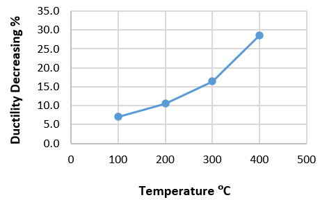
Figure 8 shows the effect of exposure of the voided slab to the temperature between (100℃ to 400℃) on the load-deflection relationship. It can be observed from this figure that raising the temperature from the room temperature to 100℃, 200℃, 300℃, and 400℃ makes the area under curve smaller, since the slab strength decrease and the deflection increase in all stages of loading as compared to the reference specimen. Also, it can be noted the part of the load-deflection curve after the first crack is more affected than that before the first crack. In the same side, Table 5 shows that the deflection at the first crack increases with raising the temperature to which the slabs are exposed from 100℃ to 200℃, 300℃ and 400℃ by percentages 4.1%, 5.5%, 11.0% and 21.9% and the ultimate deflection decrease by 3.8%, 6.1%, 7.8% and 13.5% causing decreasing the ductility ratio with percentage 7.1%, 10.5%, 16.4%, and 28.6% respectively as compared with S1. Figure 9 shows the relationship between the exposure to different temperature degrees on the ductility. This figure reveals that the decreasing of ductility with increasing the elevated temperature take ascending concave curve.
Figure 8. The impact of the exposure to different temperature degrees on load-deflection relationship
Figure 9. The impact of increasing elevated temperature on the ductility
On the other side, Figure 10 shows the effect of the exposure period to elevated temperature (400℃) on the load-deflection curve, the figure exhibits that the effect of increasing the exposure period from 1hr to 2hrs., then 3hrs. and 4 hrs. is very evident starting from the first stages of loading. It can also be seen that the effect of raising the exposure period to elevated temperature on the load-displacement curve is large in the first hour, then increases become slightly at the second hour, and then increases again at the third and fourth hour. This can be attributed to the fact that in the first hour, the effect of increasing the temperature is limited to the outer layers of the slab, and the inner layers remain unaffected, which generates high thermal stresses inside the slab, and then after the gradual spread of heat within the inner layers at the second, third and four hours, the thermal differences decrease, so the stresses generated by it decrease as compared to the effect of the first hour.
Figure 10. The impact of exposure period to elevated temperature on load-deflection relationship
Figure 11. The impact of increasing exposure period on the ductility
The deflection results of this study seem to be consistent with that of Waryosh and Hashim [19], however, their study showed that as the slab was exposed to 300℃ the deflection increased by 35% and the increase was 58% at 400℃ compared to the slab exposed to 200℃.
Furthermore, increasing the period exposure makes the deflection increases significantly in all stages of loading compared to the reference specimen, and the ultimate deflection decreases by about 13.5%, 16.9%, 20.6%, and 23.3%, causing decreasing the ductility ratio with parentages 28.6%, 40.2%, 38.6%, and 38.1% respectively. Thus, exposure to 400℃ temperatures for a period of one to four hours will greatly reduce the ductile performance. Figure 11 shows the relationship between the exposure period to elevated temperature on the ductility. This figure reflects the above results in which the decreasing of ductility with increasing the exposure period take ascending concave curve as this decrease increases steeply in the first hour and then begins to decline less fairly in the hours after the second hour, since it is clear from this figure that the exposure of the slab to a temperature of 400℃ for a period of one hour is not sufficient for the heat to reach deep levels in the slab thickness, therefore, its effect on reducing the strength of concrete and steel reinforcement and the bonding between them will be relatively little. But when the slab is exposed to a temperature of 400℃ for a period of two hours, the heat can penetrate to deeper areas in the slab, therefore its effect will be greater, and this effect increases with the increase of the exposure period to three and four hours, resulting in a clear increase in the ductility decreasing compared to the first hour.
The above results reveal that the decrease in ductility of voided concrete slabs is greater than that of the solid concrete slabs since Abdul Rahman and Tause in their previous study [18] found that the ductility of the solid SCC slabs exposed to temperatures of 100℃ and 300℃ for 2 hrs. decreased by 2.25%, and 7.126% respectively as compared with the slabs not exposed to the elevated temperature. These decreases are less than that of the current study which reached 7.1%, and 16.4% The explanation for this is similar to the explanation of the difference in the decrease in maximum resistance that is explained in the previous paragraph.
Table 5. Deflection and ductility of the voided reinforced SCC slabs
|
Slab code |
Δcr1 |
Increasing percentage of Δcr1 (%) |
∆ult2 |
Decreasing percentage of ∆ult2 (%) |
Ductility Ratio ($\frac{\Delta u l t}{\Delta c r}$) |
Decreasing percentage of ductility ratio (%) |
|
S1 |
0.73 |
- |
6.02 |
-- |
8.2 |
-- |
|
S2 |
0.76 |
4.1 |
5.79 |
3.8 |
7.6 |
7.1 |
|
S3 |
0.77 |
5.5 |
5.65 |
6.1 |
7.3 |
10.5 |
|
S4 |
0.81 |
11.0 |
5.55 |
7.8 |
6.9 |
16.4 |
|
S5 |
0.89 |
21.9 |
5.21 |
13.5 |
5.9 |
28.6 |
|
S5 |
0.89 |
21.9 |
5.21 |
13.5 |
5.9 |
28.6 |
|
S6 |
1.02 |
39.7 |
5.00 |
16.9 |
4.9 |
40.2 |
|
S7 |
0.95 |
30.1 |
4.78 |
20.6 |
5.0 |
38.6 |
|
S8 |
0.91 |
24.7 |
4.62 |
23.3 |
5.1 |
38.1 |
1 Δcr: Deflection at first crack
2 ∆ult: Ultimate deflection
This paper investigates experimentally the impact of elevated temperatures on the structural performance of voided reinforced SCC slabs. According to the outcomes of this investigation, it can be concluded from the results that:
Future works of this study may include; punching shear performance of voided reinforced concrete slabs exposed to elevated temperature, flexural behavior of reinforced high-strength concrete slabs exposed to elevated temperature, and the effect of elevated temperature on the hollow-core reinforced concrete slabs.
|
ASTM |
American Society for Testing and Materials |
|
|
℃ |
Degree Celsius |
|
|
D |
Degree of Temperature, ℃. |
|
|
fc' |
Concrete compressive strength |
|
|
hrs. |
Hours |
|
|
LVDT |
Linear Variable Differential Transformer |
|
|
Pcr |
Cracking load |
|
|
Pult |
Ultimate load |
|
|
RC |
Reinforced Concrete |
|
|
SCC |
Self-compacting concrete |
|
|
T |
Period exposure, hr. |
|
|
Greek symbols |
||
|
Δcr |
Deflection at first crack, mm |
|
|
∆ult |
Ultimate deflection, mm |
|
[1] Ma, Q., Guo, R., Zhao, Z., Lin, Z., He, K. (2015). Mechanical properties of concrete at high temperature-A review. Construction and Building Materials, 93: 371-383. https://doi.org/10.1016/j.conbuildmat.2015.05.131
[2] Alhamad, A., Yehia, S., Lublóy, É., Elchalakani, M. (2022). Performance of different concrete types exposed to elevated temperatures: a review. Material, 15(14): 5032. https://doi.org/10.3390/ma15145032
[3] Babu, N.R., Haridharan, M.K., Natarajan, C. (2015). Behaviour of two way reinforced concrete slab at elevated temperature. In: Matsagar V. (eds) Advances in Structural Engineering, Springer, New Delhi. https://doi.org/10.1007/978-81-322-2187-6_173
[4] American Concrete Institute-ACI Committee 216. (2014). Code Requirements for Determining Fire Resistance of Concrete and Masonry Construction Assemblies (ACI 216.1-14). American Concrete Institute, Farmington Hills, Michigan.
[5] Ali, W.B., Urgessa, G.S. (2014). Structural capacities of spherically voided biaxial slab (SVBS). Conference: Structures Congress 2014, pp. 785-796. https://doi.org/10.1061/9780784413357.070
[6] Sagadevan, R., Rao, B.N. (2021). Experimental and analytical investigations on two-way flexural capacity of biaxial voided slab. Advances in Structural Technologies, 233-247. http://dx.doi.org/10.1007/978-981-15-5235-9_18
[7] Mahdi, A.A., Ismael, M.A. (2021). Structural behavior of hollow-core one way slabs of high strength self-compacting concrete. International Journal of Engineering, 34(1): 39-45. https://doi.org/10.5829/IJE.2021.34.01A.05
[8] Adenan, D.S.Q.A., Kartini, K., Hamidah, M.S. (2020). Comparative study on bubble deck slab and conventional reinforced concrete slab–a review. Journal of Advanced Research in Materials Science, 70(1): 18-26. https://doi.org/10.37934/arms.70.1.1826
[9] Mahdi, A.A., Ismael, M.A. (2020). Structural behaviour of hollow core reinforced self compacting concrete one way slabs. In IOP Conference Series: Materials Science and Engineering, 888(1): 012019. https://doi.org/10.1088/1757899X/888/1/012019
[10] Vecchio, F.J., Agostino, N., Angelakos, B. (1993). Reinforced concrete slabs subjected to thermal loads. Canadian Journal of Civil Engineering, 20(5): 741-753. https://doi.org/10.1139/l93-099
[11] Sangluaia, C., Haridharan, M.K., Natarajan, C., Rajaraman, A. (2013). Behaviour of reinforced concrete slab subjected to fire. International Journal of Computer Engineering Research, 3(1): 195-206. https://doi.org/10.1016/j.aej.2013.09.004
[12] Yang, Z.N., Dong, Y.L., Xu, W.J. (2013). Fire tests on two-way concrete slabs in a full-scale multi-storey steel-framed building. Fire Safety Journal, 58: 38-48. https://doi.org/10.1016/j.firesaf.2013.01.023
[13] Levesque, A.P. (2006). Fire Performance of Reinforced Concrete Slabs. M.Sc. Thesis. Worcester Polytechnic Institute.
[14] Farhan, O.S. (2019). Experimental study on the Behaviour of different types of steel fiber reinforced concrete mix of two-way slabs subjected to different heat temperature. Journal of Engineering and Sustainable Development, 23(1): 26-42. https://doi.org/10.31272/jeasd.23.1.3
[15] Riad, M.Y., Shoeib, A.E.K. (2018). Behavior of structural lightweight polystyrene foam concrete flat slabs when exposed to fire. The Open Construction & Building Technology Journal, 12(1): 362-374. https://doi.org/10.2174/1874836801812010362
[16] Allam, S.M., Elbakry, H.M., Rabeai, A.G. (2013). Behavior of one-way reinforced concrete slabs subjected to fire. Alexandria Engineering Journal, 52(4): 749-761. https://doi.org/10.1016/j.aej.2013.09.004
[17] Abdullah, A.I., Al-Khazraji, S.D.M. (2019). Structural behavior of high strength laced reinforced concrete one way slab exposed to fire flame. Civil Engineering Journal, 5(12): 2747-2761. https://doi.org/10.28991/cej-2019-03091446
[18] Abdul Rahman, M.B., Tause, A.S. (2016). The performance of self compacting concrete slab exposed to high temperature under static and dynamic loading. Kirkuk University Journal-Scientific Studies, 11(2): 250-277. https://doi.org/10.32894/kujss.2016.124524
[19] Waryosh, W.A., Hashim, H.H. (2019). Behavior of reinforced concrete bubbled slabs exposed to fire flame under static load. International Journal of Latest Engineering Research and Applications (IJLERA), 4(12): 25-37.
[20] Jawad, H.K., Waryosh, W.A. (2021). The effect of fire flame on geopolymer bubbled slabs. International Journal of Modern Research in Engineering and Technology (IJMRET), 6(1).
[21] Jawad, H.K., Waryosh, W.A. (2021). Behavior of glass fiber geopolymer bubble slabs exposed to fire flame. Journal of Engineering and Sustainable Development (JEASD), 25(Special_Issue_2021). https://doi.org/10.31272/jeasd.conf.2.4.12
[22] Miller, O., Gericke, O., Nigl, D., Kovaleva, D., Blandini, L. (2022). Simulation-based investigations of the load-bearing behavior of concrete hollow sphere slabs exposed to fire. Fire, 5(6): 197. https://doi.org/10.3390/fire5060197
[23] Alawsi, M.A., Mhalhal, J.M., Al-Gasham, T.S., Abid, S.R. (2021). Damage assessment of RC voided slabs experienced extreme fire flame. In IOP Conference Series: Materials Science and Engineering, 1058(1): 012051. https://doi.org/10.1088/1757-899X/1058/1/012051
[24] EFNARC. (2002). Specification and guidelines for self-compacting concrete. European federation of specialist construction chemicals and concrete system. Hampshire, U.K.
[25] IQS No.5. (1984). Portland Cement. Central Agency for Standardization and Quality Control. Planning Council, Baghdad, Iraq.
[26] IQS No.45. (1984). Aggregate from Natural Sources for Concrete. Central Agency Standardization and Quality Control, Planning Council, Baghdad, Iraq.
[27] ASTM C494/C494M. (2017). Standard Specification for Chemical Admixtures for Concrete, ASTM Standard. 04.02. https://doi.org/10.1520/C0494_C0494M-17
[28] ASTM C39/C39M. (2021). Standard Test Method for Compressive Strength of Cylindrical Concrete Specimens. 04.02. https://doi.org/10.1520/C0039_C0039M-21
[29] ASTM A615/A615M. (2009). Standard Specification for Deformed and Plain Carbon-Steel Bars for Concrete Reinforcement. 01.04. https://doi.org/10.1520/A0615_A0615M-09
[30] ASTM C 192/C 192M. (2015). Standard Practice for Making and Curing Concrete Test Specimens in the Laboratory. ASTM Standard, 04.02. https://doi.org/10.1520/C0192_C0192M-15
[31] Park, R., Paulay, T. (1975). Reinforced concrete structures. Copyright © 1975 John Wiley & Sons, Inc, p. 58. https://doi.org/10.1002/9780470172834
[32] Neville, A.M. (2011). Properties of Concrete. Fifth Edition, Prentice Hall, London, England, United Kingdom.
[33] Topçu, İ.B., Karakurt, C. (2008). Properties of reinforced concrete steel rebars exposed to high temperatures. Research Letters in Materials Science, Article ID: 814137. https://doi.org/10.1155/2008/814137
[34] Elghazouli, A.Y., Cashell, K.A., Izzuddin, B.A. (2009). Experimental evaluation of the mechanical properties of steel reinforcement at elevated temperature. Fire Safety Journal, 44(6): 909-919. https://doi.org/10.1016/j.firesaf.2009.05.004
[35] Wald, F., Da Silva, L.S., Moore, D.B., Lennon, T., Chladna, M., Santiago, A., Borges, L. (2006). Experimental behaviour of a steel structure under natural fire. Fire Safety Journal, 41(7): 509-522. https://doi.org/org/10.1016/j.firesaf.2006.05.006
[36] Ergün, A., Kürklü, G., Başpınar, M.S. (2016). The effects of material properties on bond strength between reinforcing bar and concrete exposed to high temperature. Construction and Building Materials, 112: 691-698. https://doi.org/10.1016/j.conbuildmat.2016.02.213
[37] Kültür, Ö.F., Al-Masri, A., Sayin, B. (2022). Effect of high temperature exposure on design parameters and collapse behavior of reinforced concrete and steel-framed buildings. Case Studies in Construction Materials, 17: e01263. https://doi.org/10.1016/j.cscm.2022.e01263
[38] Royles, R., Morley, P.D. (1983). Further responses of the bond in reinforced concrete to high temperatures. Magazine of Concrete Research, 35(124): 157-163.
[39] Aslani, F., Samali, B. (2013). Predicting the bond between concrete and reinforcing steel at elevated temperatures. Structural Engineering and Mechanics, 48(5): 643-660. https://doi.org/10.12989/sem.2013.48.5.643
[40] Lee, J., Sheesley, E., Jing, Y., Xi, Y., Willam, K. (2018). The effect of heating and cooling on the bond strength between concrete and steel reinforcement bars with and without epoxy coating. Construction and Building Materials, 177: 230-236. https://doi.org/10.1016/j.conbuildmat.2018.05.128