Hongyuan Huang* | Guoyin Wu | Yao Rong
© 2020 IIETA. This article is published by IIETA and is licensed under the CC BY 4.0 license (http://creativecommons.org/licenses/by/4.0/).
OPEN ACCESS
For mountain tunnels in water-rich areas, the water pressure on the lining (WPOL) has a significant impact on the parameter selection and operation safety of the lining. Based on the theory of groundwater dynamics and complex function, this paper derives the analytical expressions of the WPOL and the seepage pressure outside the grouting ring. Under different supporting conditions, the authors analyzed how the WPOL was influenced by the head of groundwater, the permeability of the surrounding rock, and the permeability of the grouting ring. The results show that the permeability of the secondary lining not only affects the drainage capacity of the drainage system, but also greatly impacts the WPOL on the composite lining; the WPOL decreases linearly with the growing drainage capacity. To control the WPOL on the composite lining, designers of mountain tunnels in water-rich areas should carefully plan the water blocking and drainage control in accordance with the surrounding environment.
tunnel, water pressure on the lining (WPOL), distribution law, permeability
Water inrush is a common and serious disaster in tunnel construction [1]. The occurrence of water inrush will lead to changes in design plan and construction method. If lots of water flows into the tunnel, the shallow groundwater and surface water will be depleted, and the ground surface and building foundations will subsidize. Therefore, tunnel designers and constructors need to fully consider the influence of water pressure outside the lining (WPOL) [2].
The WPOL acts on the lining as surface force and seepage force, for the tunnel lining is not entirely impervious to water [3]. Since the lining and surrounding rock are both permeable, the water seepage between them can be considered continuous. Thus, the seepage force of water is comparable to a body force [4]. There are often many pores between the lining and surrounding rock. In this case, the body force acting on the surrounding rock cannot be directly transmitted to the lining, making the lining an independent structure under water pressure. It is an important issue for tunnel designers to correctly calculate the WPOL [5].
Many scholars have long been exploring the WPOL. In 1983, Farmer and Jennings [6] studied the effect of hydrostatic stress on mine support, and concluded that: groundwater discharge can be effectively controlled by grouting, and the WPOL can be reduced under specific conditions. After numerically analyzing seepage, Jaeger and Cook [7] combined the ground stress formed after lining construction with the coupling effect between groundwater permeability of surrounding rock and lining to calculate the WPOL. Lee et al. [8, 9] reported that the drainage system will be squeezed during lining construction, and blocked by the migration of soil particles during use, which in turn will increase the WPOL. In 2005, Raymer [10] pointed out that water flows only in connected fractures in hard rock, and the inflow is usually concentrated in fissure dense areas. To disclose the hydraulic interaction between lining and surrounding rock, Nam et al. [11] numerically simulated the effect of pore water pressure on the displacements of lining and surrounding rock, identified lining permeability and working condition of drainage system as the main factors affecting the WPOL, and put forward the WPOL load curve. Louis [12, 13], Zimmerman et al. [14], Louis and Maini [15] suggested that the lining must withstand a static head pressure of 20%, if the permeable cushion layer continuously drains groundwater. Arjnoi et al. [16] studied the distribution law of pore water pressures and internal force of tunnel surrounding rocks and lining under different drainage conditions by numerical simulation.
To sum up, the existing studies provide good reference for many aspects of tunnel design, namely, the WPOL calculation, the structural features under stress, water blocking and drainage control, etc. In actual project, groundwater can only be discharged from the tunnel through the drainage system behind the lining, rather than through the lining. However, many factors that are important to the WPOL and tunnel design in groundwater-rich areas have not been considered as influencing factors of the WPOL, such as the layout, degradation, and blockage of the drainage system, as well as the safety, reliability, and maintenance of the lining during operation [17-22].
For a deep-buried tunnel, the groundwater is discharged not only from the two sides, but also in the axial direction. In the axial direction, the inflow mainly comes from the front of tunnel face. After the tunnel being constructed is sufficiently long, the groundwater in the constructed section can be considered as moving from both sides of the tunnel into the section. At this time, the three-dimensional (3D) problem of tunnel drainage becomes a two-dimensional (2D) problem. If the cross-section of the deep-buried tunnel is way smaller than the thickness of the top aquifer, each part suffering local water inrush can be treated a point, whose drainage function is equivalent to a well. The drainage of the tunnel disturbs the seepage field, causing changes to the head pressure.
Under the complex conditions of hydrogeology and rock occurrence, the seepage in surrounding rock and lining of the deep-buried tunnel can be summarized as the movement of confined water to vertical wells. To study the WPOL of a circular tunnel with water blocking and drainage control design (grouting measures), the following assumptions were put forward:
(1) The surrounding rock is a homogeneous and isotropic continuous medium, and the groundwater is incompressible. The permeability K in each direction follows Darcy’s law. The seepage speed is directly proportional to the hydraulic gradient.
(2) There is sufficient groundwater recharge. The recharge ability far exceeds the drainage ability of the tunnel. The groundwater level remains constant, and the head does not drop. That is, the groundwater seepage reaches a stable flow state, and the distant water potential H remains constant, regardless of the initial seepage field.
(3) The stress field of the surrounding rock, and the coupling effect between seepage field and stress field are not considered.
(4) Around the tunnel is the boundary of the equal head. Water is released when the head drops. The drainage of the tunnel is characterized by the uniform seepage of the lining, irrespective of the waterproof layer of the tunnel.
Under the above assumptions, a simplified axisymmetric calculation model was constructed as shown in Figure 1, where kl, kr, and kg are the permeability of the lining, the surrounding rock, and the grouting ring, respectively; r is the polar distance of the target point; r0 and rl are the inner and outer diameters of the lining, respectively; rg is the outer diameter of the grouting ring.
Figure 1. The simplified axisymmetric calculation model
Darcy’s law and continuity equation can be expressed in axisymmetric forms:
$\frac{Q}{2\pi r}=k\frac{dh}{dr}, Q=const\left( r \right)$ (1)
where, Q is flow; k is the seepage of the medium; r is polar distance; h is water head.
The axial direction of the tunnel is z-axis. The seepage satisfies the Laplace continuity equation:
${{\nabla }^{2}}h=0$ (2)
In cylindrical coordinates, formula (2) can be rewritten as:
$\frac{1}{r}\frac{\partial }{\partial r}\left( r\frac{\partial h}{\partial r} \right)+\frac{1}{{{r}^{2}}}\frac{{{\partial }^{2}}h}{\partial {{\theta }^{2}}}+\frac{{{\partial }^{2}}h}{\partial {{z}^{2}}}=0$ (3)
Since the water flow is perpendicular to the z-axis, $\frac{\partial h}{\partial z}=0$. Meanwhile, the head field function h is symmetrical about the z=axis, indicating that $\frac{\partial h}{\partial \theta}=0$. Formula (3) can be simplified as $\frac{1}{r} \frac{d}{d r}\left(r \frac{d h}{d r}\right)=0$, and integrated as $r\frac{d h}{d r}=C$.
The flow rate is equal at different cross-sections. According to Darcy’s law, the flow rate per linear meter of the tunnel can be calculated by:
$Q=2\pi rk\frac{dh}{dr}$ (4)
$C=\frac{Q}{2\pi k}, and r\frac{dh}{dr}=\frac{Q}{2\pi k}$ (5)
Through variable separation, we have $d h=\frac{Q}{2 \pi k} \frac{1}{r} d r$.
Then, the boundary conditions can be introduced as r=r2, h=H; r=rg, h=hg; r=rl, h=hl; r=r0, h=h0. Finding the integrals of the variable dh:
$\left\{ \begin{matrix} \int_{{{h}_{g}}}^{H}{dh}\text{=}\frac{Q}{2\pi {{k}_{r}}}\int_{{{r}_{g}}}^{{{r}_{2}}}{\frac{1}{r}dr} \\ \int_{{{h}_{l}}}^{{{h}_{g}}}{dh}\text{=}\frac{Q}{2\pi {{k}_{g}}}\int_{{{r}_{l}}}^{{{r}_{g}}}{\frac{1}{r}dr} \\ \int_{{{h}_{0}}}^{{{h}_{l}}}{dh}\text{=}\frac{Q}{2\pi {{k}_{l}}}\int_{{{r}_{0}}}^{{{r}_{l}}}{\frac{1}{r}dr} \\ \end{matrix} \right.$ (6)
That is, $\frac{2 \pi k_{r}(H-h g)}{\ln \left(\frac{r_{2}}{r_{g}}\right)}=\frac{2 \pi k_{g}\left(h_{g}-h_{l}\right)}{\ln \left(\frac{r_{g}}{r_{l}}\right)}=\frac{2 \pi k_{l}\left(h_{l}-h_{0}\right)}{\ln \left(\frac{r_{l}}{r_{0}}\right)}$.
From the above formula, it can be seen that r2=H and h0=0. In this case, there is no water inside the tunnel. Then, the body force on the surrounding rock, the water pressure on the interface between surrounding rock and lining, and the water pressure on the grouting ring can be respectively obtained by:
${{P}_{l}}=\gamma {{h}_{l}}=\frac{\gamma H\ln \frac{{{r}_{l}}}{{{r}_{0}}}}{\frac{{{k}_{l}}}{{{k}_{r}}}\ln \frac{H}{{{r}_{g}}}+\frac{{{k}_{l}}}{{{k}_{g}}}\ln \frac{{{r}_{g}}}{{{r}_{l}}}+\ln \frac{{{r}_{l}}}{{{r}_{0}}}}$ (7)
$\begin{align} & {{P}_{g}}=\gamma {{h}_{g}} \\ & =\frac{\gamma H\ln \frac{{{r}_{g}}}{{{r}_{l}}}}{\frac{{{k}_{g}}}{{{k}_{r}}}\ln \frac{H}{{{r}_{g}}}+\ln \frac{{{r}_{g}}}{{{r}_{l}}}}+\frac{\gamma {{h}_{l}}\ln \frac{H}{{{r}_{g}}}}{\ln \frac{H}{{{r}_{g}}}+\frac{{{k}_{r}}}{{{k}_{g}}}\ln \frac{{{r}_{g}}}{{{r}_{l}}}} \\ & \text{=}\gamma H-\frac{\gamma H\ln \frac{H}{{{r}_{g}}}}{\ln \frac{H}{{{r}_{g}}}+\frac{{{k}_{r}}}{{{k}_{g}}}\ln \frac{{{r}_{g}}}{{{r}_{l}}}+\frac{{{k}_{r}}}{{{k}_{l}}}\ln \frac{{{r}_{l}}}{{{r}_{0}}}} \\ \end{align}$ (8)
where, kl, kg, and kr are the permeability of the lining, grouting ring, and surrounding rock, respectively; r0 and rl are the inner and outer diameters of the lining, respectively; rg is the radius of the grouting ring; hl, hg, and H are the water heads outside the lining, outside the grouting ring, and at the center of the tunnel (hereinafter referred to as the center water head), respectively.
The following analysis is based on several special cases.
(1) Without considering grouting, make kg=kr and rg=rl in formula (7):
${{P}_{l}}=\frac{\gamma H\ln {{{r}_{l}}}/{{{r}_{0}}}\;}{\frac{{{k}_{l}}}{{{k}_{r}}}\ln \frac{H}{{{r}_{l}}}+\ln \frac{{{r}_{l}}}{{{r}_{0}}}}$ (9)
(2) In actual engineering, the lining is not adhered to the surrounding rock everywhere, and usually applied with a waterproof cloth. Therefore, the water passing through the surrounding rock is directly drained out of the tunnel through the drainage system instead of the lining. Hence, the lining permeability kl can be viewed as infinite, i.e. the lining has no effect during the derivation. From formula (9), it can be seen that the WPOL is zero at this time.
According to (5), the relationship between the water head outside the lining and the amount of water inrush or drainage can be obtained:
${{h}_{l}}=H-\frac{Q}{2\pi {{k}_{r}}}\ln \frac{{{r}_{2}}}{{{r}_{g}}}-\frac{Q}{2\pi {{k}_{g}}}\ln \frac{{{r}_{g}}}{{{r}_{l}}}$ (10)
During tunnel construction, the reinforced tunnel needs secondary reinforcement, i.e. secondary lining. As waterproof slabs are laid outside the secondary lining, the lining can be considered as impermeable. If the tunnel is closed without any drainage system, the flow rate Q will be zero. Substituting Q=0 into formula (10), the water head on the lining will reach center water head, that is, hl=H.
If the tunnel is drained without any control, the water behind the lining will completely discharged, eliminating the possibility of seepage. Under this condition, the water pressure behind the lining is zero, and the maximum amount of water inrush per linear meter of the tunnel can be obtained.
From the above formulas, the groundwater seepage and WPOL are affected by the permeability kr of the surrounding rock, the tunnel diameter r0, the outer diameter r1 of the secondary lining, the permeability k1 of the secondary lining, the external diameter rg of the grouting ring, the permeability kg of the grouting ring, and the center water head H. Among them, kr, r0, and H are natural factors, reflecting the environment of the tunnel; k1, rl, rg, and kg are engineering factors, which should be controlled to meet the engineering requirements.
Next, the influence of each factor on the WPOL was explored with or without grouting, and the relationship between the WPOL and displacement was analyzed in details. The calculation parameters were configured as follows: If the tunnel is non-circular, the cross-section of the lining is equivalent to a circle, whose inner diameter was set to r0 = 4.94m; if the tunnel passing through a fault zone, the surrounding rock will be moderately weathered, whose permeability was set to 0.200m/d, 0.0277m/d, and 0.325m/d, respectively; the lining thickness was set to 35cm, 40cm, 45cm, and 50cm, respectively; the center water head H was set to 50m, 100m, and 150m, respectively.
3.1 Case 1: Without grouting
(1) The relationship between the WPOL and the permeability of the surrounding rock
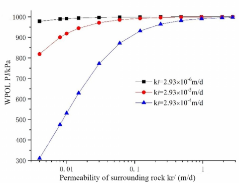
Figure 2 shows the relationship between the WPOL and surrounding rock permeability, at the lining thickness of 50cm and the center water head H of 100m. It can be seen that, when the lining permeability remained constant, the WPOL increased with surrounding rock permeability. As the surrounding rock became increasingly preamble, the WPOL initially surged up, then increased slowly, and finally tended to be stable. When the surrounding rock permeability reached kr=0.4m/d, the relationship curves between the WPOL and surrounding rock permeability converged, indicating that, when the surrounding rock permeability reaches a certain extent, the slight permeability change of lining concrete material has no impact on the WPOL, and the WPOL will remain constant at certain value.
Figure 2. The relationship between the WPOL and surrounding rock permeability
(2) The relationship between the WPOL and the permeability of the lining
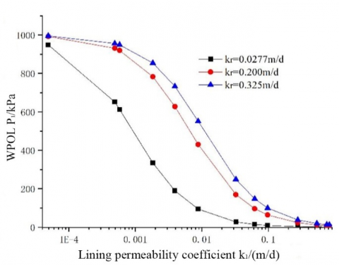
The relationship between the WPOL and the permeability of the lining was investigated at the lining thickness of 50cm, under different surrounding rock permeability and center water heads. Figure 3 displays the relationship between the WPOL and lining permeability at H=100m. It can be seen that, when the surrounding rock permeability remained constant, the WPOL decreased with the lining permeability, and approached zero after the lining permeability reached 0.3m/d. This means the WPOL can be effectively reduced by increasing the lining permeability or arraigning reasonable drainage holes.
It can also be seen in Figure 3 that the WPOL increased with the surrounding rock permeability. The three relationship curves converted at the two ends, indicating that the WPOL is not affected by surrounding rock permeability, but only by the lining permeability, when the lining permeability is too large or too small.
Figure 3. The relationship between the WPOL and lining permeability
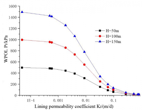
Figure 4 presents the relationship between the WPOL and lining permeability at the surrounding rock permeability of 0.325m/d and center water head H of 50m, 100m, and 150m, respectively. It can be seen that, under each center water head, the WPOL decreased with the growing lining permeability: when the lining permeability was small, the WPOL is greatly affected by the center water head; as the lining permeability climbed up to 0.3m/d, the curves approximated the x-axis, suggesting that the WPOL is no longer affected by the center water head and reduced to zero, when the lining permeability increases to a certain threshold.
Figure 4. The relationship between the WPOL and center water head
(3) The relationship between the WPOL and lining thickness
Figure 5 records the relationship between the WPOL and lining thickness at the center water head H of 100m, and the permeability ratio n=kr/kl between surrounding rock and grouting ring at n=10, n=100, and n=1,000, respectively. It can be seen that, when the lining thickness increased below 0.5m, the WPOL rocketed up; when the lining thickness increased above 0.5m, the WPOL increased slightly. In particular, when the lining thickness was above 0.5m and n=1,000 (the lining is almost impervious), the WPOL was close to the hydrostatic stress, and was hardly reduced.
Figure 5. The relationship between the WPOL and lining thickness
3.2 Case 2: With grouting
From formula (7), it can be known that Pl decreases regardless of whether rg increases or kg decreases. In other words, if and only if the lining has drainage effect, the WPOL can be reduced or eliminated through grouting. The following is an analysis on how the permeability and thickness of the grouting ring affect the WPOL. The calculation parameters were configured as: equivalent circle radius r0=4.94m, lining thickness=0.5m, rl=5.44M, kr=0.325m/d, kl=2.93×10⁻³m/d, center water head H=100m, the permeability ratio between the surrounding rocks and grouting ring n=kr/kg.
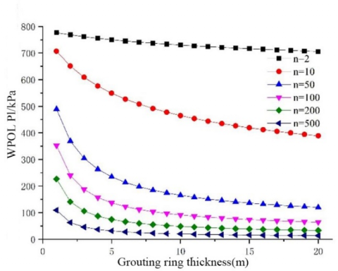
Figure 6. The relationship between the WPOL and parameters of the grouting ring
Figure 6 shows the relationship between the WPOL and the thickness of the grouting ring. It can be seen that the WPOL decreased with the growing thickness and the reducing permeability of the grouting ring. This means the WPOL can be further reduced by improving the water blocking effect of the grouting ring, when the design parameters of the drainage system remain the same. When n ≥100 and tg ≥8m, the WPOL decrement was not obvious, whether the grouting ring was made thicker or less permeable. Similar to controlling the water inrush to the tunnel, the WPOL reduction does not necessarily improves with the growing thickness or reducing permeability of the grouting ring. There are relatively economical and reasonable values of these parameters.
3.3 Relationship between drainage and WPOL
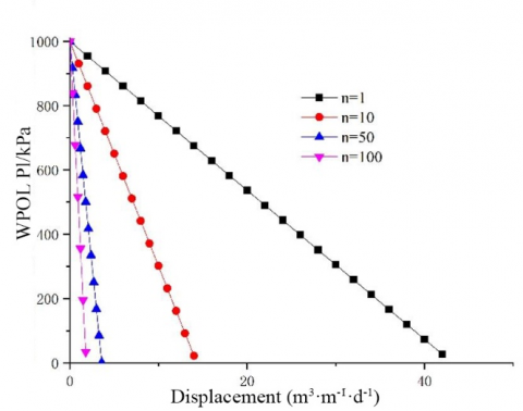
The relationship between drainage and the WPOL was investigated by formula (10), based on grouting rings with different permeability and thicknesses. If the drainage system cannot timely discharge all the groundwater behind the secondary lining, the water blocking effect of the secondary lining must be taken into account. The calculation parameters were configured as: the center water head H = 100m, the lining thickness= 0.5m, the grouting ring thickness=5m, kr=0.2m/d, and n=10.
(a)Different permeability of grouting ring
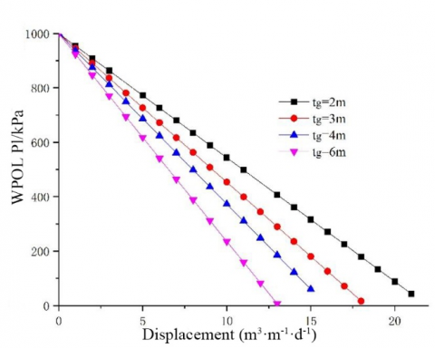
(b) Different thickness of the grouting ring
Figure 7. The relationship between drainage and the WPOL
Figure 7 illustrates the relationship between the WPOL on the secondary lining and drainage. Specifically, Figure 7(a) shows the relationship between the WPOL and drainage at the thickness of 5m and different permeability of the grouping ring. It can be seen that: when the drainage was zero (the tunnel is completely waterproof), the WPOL did not drop regardless of the water blocking effect of the grouting ring; the WPOL linearly decreased with the growing drainage (the drainage capacity of the drainage system).
When the displacement was sufficiently large, the water accumulated behind the lining was completely discharged, and the WPOL dropped to zero. When the displacement remained the same, the WPOL decrement increased with the water blocking effect of the grouting ring. Hence, the grouting ring cannot reduce the WPOL until drainage measures are taken. Moreover, the drainage volume needed to achieve the same WPOL dropped with the growing water blocking effect of the grouting ring.
When the displacement was zero (without drainage system), no matter how small the permeability of grouting ring, the water pressure HL behind the lining would reach the center water head H. To control the WPOL, the drainage system must be combined with proper parameters of the grouting ring.
Figure 7(b) shows the relationship between the drainage and the WPOL on the secondary lining at different grouting ring thicknesses. It can be seen that the water pressure on the secondary lining decreased linearly with the growing drainage. With the increase of the water blocking effect (the increase of thickness and reduction of permeability of the grouting ring), the water pressure-drainage curve became steeper. Compared with thickness, the change of grouting ring permeability has a greater effect on the suppression of the WPOL by drainage.
This paper mainly discusses the distribution law of the WPOL on the secondary lining in the tunnel. The authors derived the WPOLs on an actual tunnel with or without grouting, and summarized the change law of the WPOL under multiple factors. The following discusses the grouting measures in the light of the WPOL.
4.1 Without grouting
When the lining permeability is kl≤1.0×10⁻⁴m/d or kc≥0.3m/d, the WPOL is not greatly affected by the surrounding rock permeability. When kl≥0.3m/d, the WPOL approximates zero. This means the WPOL can be effectively reduced by increasing the lining permeability or designing reasonable drainage holes.
When the surrounding rock permeability is kr≥0.4m/d, the WPOL is not affected by the slight changes in lining permeability, and remains constant. The permeability ratio n between the surrounding rock and the lining has a great impact on the WPOL. The smaller the ratio, the smaller the WPOL. The inverse is also true.
To effectively reduce the WPOL, it is necessary to lower the permeability of the surrounding rock, while increasing the permeability of the lining. This principle should be adopted by all waterproof and drainage tunnels to stabilize the surrounding rock and lining. The specific engineering measures include making reasonable arrangement of drainage holes, grouting the surrounding rock, and properly increasing the permeability of lining concrete materials.
4.2 With grouting
The tunnel drainage decreases with the growing thickness or reducing permeability of the grouting ring. The decline of the WPOL will ensue. When the grouting ring reaches a certain thickness, the WPOL will no longer decrease obviously. When the grouting ring achieves the optimal thickness, the WPOL will cease decreasing. Therefore, the grouting ring thickness should be properly selected to realize good water blocking effect at a reasonable cost.
The discharge of groundwater mainly depends on the grouting, and the unloading of the WPOL hinges on the lining permeability and the drainage method. If the lining permeability is sufficiently small or the drainage system supports full blocking, the WPOL cannot be reduced whether the grouting ring becomes thicker or less permeable. Therefore, if the lining has a proper permeability or the drainage system is effective, grouting the surrounding rock can limit the groundwater discharge, and also reduce the WPOL.
4.3 Influencing factors of the WPOL
From the above analysis, it can be seen that the WPOL is closely related to the head of groundwater, the permeability of the surrounding rock, thickness and permeability of the grouting ring (the design of the drainage system), and the permeability of lining.
In mountain tunnels, the WPOL on the composite lining directly bears on the performance of a drainage system, and decreases linearly with the growing drainage capacity. If the tunnel lies in a water-rich area, the WPOL should be regulated by designing the plan for water blocking and drainage control in accordance with the surrounding environment. The following points should be noticed during the design:
(1) The designed WPOL should match the drainage capacity of the tunnel. Fully consideration should be given to the reduction of drainage capacity induced by sedimentation and external force extrusion.
(2) The design of the drainage system should focus on the slope of blind, longitudinal, and transverse drainage pipes. Special drainage medium with smooth surface could be adopted if conditions permit, aiming to minimizing the effect of sediments (e.g. silt and calcium ion) on drainage capacity.
(3) During the construction, the drainage system should be fully protected to prevent local deformation and blockage under external construction forces.
(4) The designer must pay attention to the suppression effect of the grouting ring on the WPOL on the composite lining. The thickness of the grouting ring should be controlled between 6m and 8m.
(5) The permeability of the grouting ring should match the drainage capacity of the drainage system. The WPOL on the composite lining will be small, when the drainage capacity of the system is greater than that of the grouting ring.
The authors gratefully acknowledge the financial supports from the Natural Science Foundation Project of China (Grant No.: 52068033), and the Science and Technology Project of Jiangxi Provincial Department of Transport (Grant No.: 2018C0028).
[1] Zhao, X., Yang, X. (2019). Experimental study on water inflow characteristics of tunnel in the fault fracture zone. Arabian Journal of Geosciences, 12(13): 399. https://doi.org/10.1007/s12517-019-4561-3
[2] Huang, Y., Fu, Z., Chen, J., Zhou, Z., Wang, J. (2015). The external water pressure on a deep buried tunnel in fractured rock. Tunnelling and Underground Space Technology, 48: 58-66. https://doi.org/10.1016/j.tust.2015.02.003
[3] Zhang, X., Jiang, Z., Feng, S., Chen, S. (2011). Study on the determination of permeability coefficient of fractured rock mass under high pressure test condition. Journal of Hydroelectric Engineering, 30(1): 155-159.
[4] Ren, W.F. (2013). Theory research of stress field displacement field and seepage field and study on grouting waterproofing of high water pressures tunnel. Central South University.
[5] Morsali, M., Nakhaei, M., Rezaei, M., Hassanpour, J., Nassery, H. (2017). A new approach to water head estimation based on water inflow into the tunnel (case study: Karaj Water Conveyance Tunnel). Quarterly Journal of Engineering Geology and Hydrogeology, 50(2): 126-132. https://doi.org/10.1144/qjegh2016-015
[6] Farmer, I.W., Jennings, D.H. (1983). Effect of strata permeability on the radial hydrostatic pressures on mine shaft linings. International Journal of Mine Water, 2(3): 17-24. https://doi.org/10.1007/BF02504569
[7] Jaeger, J.C., Cook, N.G.W. (1979). Fundamentals of Rock Mechanics (3rd ed.). London: Chapman and Hall, 86-88.
[8] Lee, I.M., Kim, J.H., Reddi, L.N. (2002). Clogging phenomena of the residual soil-geotextile filter system. Geotechnical Testing Journal, 25(4): 379-390. https://doi.org/10.1520/GTJ11299J
[9] Lee, I.M., Nam, S.W. (2004). Effect of tunnel advance rate on seepage forces acting on the underwater tunnel face. Tunnelling and Underground Space Technology, 19(3): 273-281. https://doi.org/10.1016/j.tust.2003.11.005
[10] Raymer, J.H. (2005). Groundwater inflow into hard rock tunnels: A new look at inflow equations. In Rapid Excavation and Tunneling Conference, pp. 457-468.
[11] Nam, T.S., Joo, E.J., Choi, G.C., Shin, J.H. (2007). Hydraulic lining–ground interaction of subsea tunnels. Chinese Journal of Rock Mechanics and Engineering, 26(S2): 3674-3681.
[12] Louis, C. (2011). Rock Hydraulics in Rock Mechanics. Verlay Wien New York.
[13] Louis, C. (2011). A study of groundwater flow in jointed rock and its influence on the stability of rock masses. London: Imperial College.
[14] Zimmerman, R.W., Chen, G., Hadgu, T., Bodvarsson, G.S. (1993). A numerical dual-porosity model with semianalytical treatment of fracture/matrix flow. Water Resources Research, 29(7): 2127-2137. https://doi.org/10.1029/93WR00749
[15] Louis, C., Maini, Y.N. (1970). Determination of in-situ hydraulic parameters in jointed rock. International Society of Rock Mechanics, Proceedings, 1(1-32): 234-245. https://trid.trb.org/view/127706
[16] Arjnoi, P., Jeong, J.H., Kim, C.Y., Park, K.H. (2009). Effect of drainage conditions on porewater pressure distributions and lining stresses in drained tunnels. Tunnelling and Underground Space Technology, 24(4): 376-389. https://doi.org/10.1016/j.tust.2008.10.006
[17] Zhang, Y.T. (2003). Discussion on external hydraulic pressure upon rock tunnel lining Mod. Tunn. Technol., 40(3): 1-4.
[18] Shin, H.S., Youn, D.J., Chae, S.E., Shin, J.H. (2009). Effective control of pore water pressures on tunnel linings using pin-hole drain method. Tunnelling and Underground Space Technology, 24(5): 555-561. https://doi.org/10.1016/j.tust.2009.02.006
[19] Bian, K., Xiao, M., Chen, J. (2009). Study on coupled seepage and stress fields in the concrete lining of the underground pipe with high water pressure. Tunnelling and Underground Space Technology, 24(3): 287-295. https://doi.org/10.1016/j.tust.2008.10.003
[20] El Tani, M. (2003). Circular tunnel in a semi-infinite aquifer. Tunnelling and Underground Space Technology, 18(1): 49-55. https://doi.org/10.1016/S0886-7798(02)00102-5
[21] Kolymbas, D., Wagner, P. (2007). Groundwater ingress to tunnels–the exact analytical solution. Tunnelling and Underground Space Technology, 22(1): 23-27. https://doi.org/10.1016/j.tust.2006.02.001
[22] Huangfu, M., Wang, M.S., Tan, Z.S., Wang, X.Y. (2010). Analytical solutions for steady seepage into an underwater circular tunnel. Tunnelling and Underground Space Technology, 25(4): 391-396. https://doi.org/10.1016/j.tust.2010.02.002