Mehran Rabani* | Vali Kalantar | Mehrdad Rabani | Ramin Rabani
© 2020 IIETA. This article is published by IIETA and is licensed under the CC BY 4.0 license (http://creativecommons.org/licenses/by/4.0/).
OPEN ACCESS
With the shortage of the energy and the improvement of people's environmental requirements, it has received more and more attention to realize building energy efficiency through new energy sources. Trombe wall is a technology that uses solar energy and wind energy to enhance indoor natural ventilation, thereby achieving indoor temperature and humidity reduction and improving air quality. In this paper, the impact of rectangular fin arrays on the cooling performance of a combined solar system, consisted of Trombe wall, Solar chimney, and water spraying system (WSS), was experimentally investigated. Different fin types including copper, aluminum and brass fins were considered. The experimental room measuring 3m×2m×3m was located in Yazd, Iran, characterized with hot and dry climate. The cooling performance was assessed in terms of fin materials and the number of fins. The results showed that using water spraying system, the room temperature decreased up to 10°C. The cooling efficiency of the system with thermal fin increased up to 6%. Furthermore, the copper fin resulted in maximum cooling efficiency and more comfortable average room temperature than two other fin types.
Trombe wall, solar chimney, water spraying system, thermal fin
The use of fossil fuels increased dramatically with the development of science and technology following the Industrial Revolution. This intensified the emission of CO2 and some other gases such as carbon monoxide and sulfur trioxide in the atmosphere and disorganized their natural cycles. On the other hand, as the consumption rate of fossil fuels is higher than their production rate, their depletion is expected in the future [1].
In order to reduce the fossil fuels consumption and prevent excess greenhouse gas emissions, renewable energy resources such as the sun, wind etc., with no environmental footprint, have been introduced. Unlike fossil and nuclear fuels, these resources have no access limitations and are freely available [2].
Solar energy is one of these renewable sources, which has many applications such as in Trombe walls. Although Trombe walls are mostly known for their heating application, their cooling performance is also interesting. Trombe walls are type of the energy storage walls that, in addition to heating and cooling a space, can store the thermal energy during the heating and cooling process and release it when needed. They are normally placed on south-facing building walls to receive the highest amount of solar radiation. Trombe walls are constructed from a massive wall with different materials and energy storage capabilities and have typically two vents in their top and bottom for ventilation and circulation of air inside the room. The stored energy within the wall, released during non-sunny period, can be used for space heating. In addition to creating comfort conditions, Trombe walls are economical and almost cost-effective to repair, so they are a good option for enhancing natural cooling and heating in the interior space of the buildings.
Many researches have investigated the Trombe wall performance, mostly related to the heating application of the system [3-10]. It was found out that a 20 cm thick concrete wall provides suitable indoor heating conditions (25°C) [3-5]. Furthermore, findings supported that that the Trombe wall can provide suitable indoor conditions, but it has some disadvantages such as heat loss from glasses to environment, the reverse thermo circulation during the night etc. that can be eliminated by certain solutions [6-10].
Furthermore, various studies have addressed the effect of different size of the Trombe wall components on the system performance [11-14]. Optimum dimensions of the Trombe wall have significant effect on its performance. The investigations on the natural building ventilation generated by Trombe wall were carried out parametrically and experimentally. The results showed that the amount of stored energy increases with the increase in the area ratio of the Trombe wall to the southern building wall [11, 12]. Moreover, with an increase in the room temperature, the rate of solar radiation, and the height as well as the thickness of the Trombe wall, the rate of the natural ventilation increased [13, 14].
The impact of applying different materials to the Trombe wall has also been reported [15-18]. The results showed that the Trombe wall material has a significant effect on its performance. Rabani et al. investigated the numerical simulation of a Trombe wall to predict the energy storage rate and the time duration of room heating during the non-sunny periods [15]. The wall energy saving was obtained for the different materials used in the construction of the Trombe wall. The results showed that the Trombe wall made of paraffin wax could maintain the room warm longer in comparison with other materials such as brick, concrete and hydrated salt for about 9h. Other works conducted numerical studies to investigate the effect of wall material and thickness on indoor air temperature variation. Three types of materials including concrete, the hydrated salt and paraffin wax were examined. According to the results, a storage wall made of these types of material provided suitable temperature for the room, but the range of room temperature variation for the wall made of the hydrated salt was 18–22°C while for two other types was 15–25°C [16-18].
Regarding the cooling application of Trombe wall, its performance has been evaluated in several hybrid systems [19-24]. The experimental studies were carried out to analyze the combination performance of the Trombe wall with the solar chimney and water spraying system during the summer. This hybrid system could enhance the natural convection heat transfer rate and provide suitable indoor conditions. Additionally, by using water spraying system, the thermal efficiency of the system was improved by approximately 30%. In addition, integration of thermal fins with Trombe wall system has shown a good potential in improving its performance.
Wongwuttanasatian et al. studied the improvement of passive cooling for a photovoltaic (PV) device in a finned container heat sink [25]. Three different PCM containers were applied and tested. The aim was to investigate the reductions in surface temperatures and therefore enhancements in PV performance. The results showed that using a low-cost palm wax as the PCM was suitable to cool down the PV device when the PV temperature was around 50-55°C and the environment temperature was over 30°C. In addition, a finned PCM box cooling could improve the averaged performance ratio of the device around 5%.
Micheli et al. improved the passive concentrating photovoltaics (CPV) cooing performance using micro-fins [26]. The improvement was doubled by using micro-fins with maximized fin effectiveness. The mass specific power was six times higher than for standard CPV heat sinks. The results also showed that maximizing the mass specific heat transfer resulted in an increase of 50% in mass specific power compared to a flat surface.
Grubisic-Cabo et al. conducted a passive cooling technique for photovoltaic (PV) panels in order to reduce the operating temperature of PV panel and thereby improve the energy conversion efficiency of the panel [27]. The considered passive cooling system was comprised of several aluminum fins embedded with epoxy conductive glue on the PV panel backside surface. Two specific configurations were used on the backside surface of PV panel in order to increase the cooling efficiency of the system. The first configuration consisted of parallel positioned aluminum fins (L-profile) and the second configuration was formed by randomly positioning of perforated L profiles. The results revealed that the first method was less efficient than the second one.
Deng and Liu numerically assessed the condensation performance and freezing risk of the condensers equipped with finned tube air-cooled [28]. The results showed that, under a cross natural wind, increasing the normal velocity of the cooling airflow through the finned tube bundles could considerably increase the freezing risk of downwind condensers.
Vittorini and Cipollone investigated the modeling of a fin-cooled photovoltaic device under real operating conditions [29]. Various layouts were analyzed in terms of fins geometry and the effect of fins mass on the heat capacity. The fins potential in the control of module temperature and improvement of electric efficiency was evaluated and the results showed that such layout would be of interest with more robust cooling techniques.
As the literature study showed, the integration of Trombe wall with other passive heating and cooling systems could improve its performance. Therefore, in this study, we evaluated the hybrid performance of a Trombe wall system, with new design of channel, equipped with several vertical thermal fins. A similar study was already performed on the heating application of this hybrid system [10]. However, the aim in the present study was to address the effect of materials and the number of fins on the cooling performance of this hybrid system, which is a crucial need in the countries dominated with a hot and dry climate.
The rest of the paper is organized as follows. Section 2 will introduce the description of the research method and experimental setup. Section 3 will describe the results. The first part of it will investigate the cooling performance of the system based on the material of fins and the second part will analyze the number of the fin on the performance of the system. The fourth part will discuss about the results and the final part will be the conclusion of results.
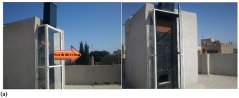
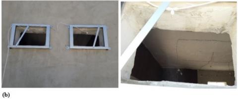
Figure 1 shows the case study comprising a passive solar Trombe wall system integrated to an experimental test room measuring 3m×2m×3m located in Yazd, Iran. In addition, the schematic performance of the hybrid system is shown in Figure 2.
Figure 1. (a) Hybrid system configuration (b) water spraying system (WSS) at the back of the room [19]
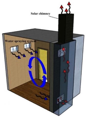
Figure 2. Schematic performance of the hybrid system [19]
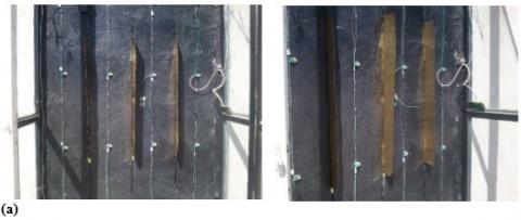
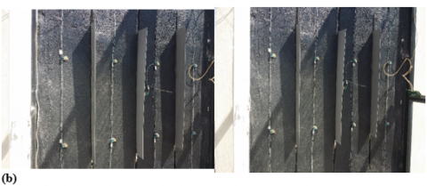
As the thermal fin is generally used for increasing the rate of convection heat transfer, we assessed the performance of three types of fin including brass, aluminum, and copper placed on the Trombe wall absorber (Figure 3). Table 1 shows the features of three fin types. The fins were vertically installed on the several vertical grooves on the absorber of the Trombe wall (Figure 3) [10].
The size of grooves and how the fins were installed in the grooves were elaborated in the previous work [10].
Figure 3. Installing thermal fin on the Trombe wall absorber for (a) brass fin, (b) aluminum fin and (c) copper fin [10]
Table 1. Thermal fin properties [10]
|
Type |
Density (Kg/m3) |
Dimension |
Thermal conductivity (W/m.K) |
|
Brass |
8530 |
10×100Cm2×1mm |
110 |
|
Aluminum |
2702 |
10×100Cm2×1mm |
237 |
|
Copper |
8933 |
10×100Cm2×1mm |
401 |
2.1 Description of the research method
In this study, the cooling performance of a test room equipped with the new designed Trombe wall coupled with solar chimney, water spraying system, and thermal fins was investigated experimentally. The test room placed in Yazd with hot and dry climate (Iran, latitude: 31°53'50"N; longitude: 54°22'3"E; altitude: 1230 m).
All optimum dimensions of the system were selected based of the previous works [8, 19]. It was necessary to isolate the room completely to reach the optimal performance. Regarding the envelop conditions, 14 cm foam along with 5 cm covering for both inner and outer surface of the test room walls with a mixture of thatch and concrete, which is a suitable thermal insulating material has been used [8, 10, 19]. In addition, the white cement was used to cover the outside of the room walls. The inside of the room walls was covered with waterproof and heat resistant water-based acrylic color to ensure the walls were completely insulated.
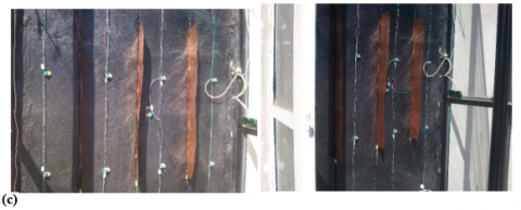
In order to collect the enough temperature data and relative humidity in various sections of the system, the number and the type of the sensors were selected. The type of temperature sensor was DS18B20 and the type of temperature-humidity sensor was SHT75 [8, 10, 19]. The DS18B20 sensor was waterproof and read air temperature. It was also suitable for measuring surface temperature and measures temperature from -55°C to +125°C with ±0.5°C accuracy. The SHT75 sensor had a relative humidity operating range from 0% to 100% with ±1.8% accuracy and could also measure temperature from -40°C to +123.8°C with ±0.3°C accuracy (Figure 4) [8, 10, 19]. The data including the temperature of the Trombe wall absorber, back face of the Trombe wall, left, right, and front glasses, as well as the temperature inside the test room were collected every 15 minutes and stored within the data logger for further analysis and averaging [8, 10, 19]. The solar power meter (TES-1333R) and the hotwire anemometer (TSI-ALNOR 9535) have been used in order to measure the solar intensity received by the absorber and the air velocity in the channel, respectively. They collected the data every 15 min and store them like other data sensors. Detail information about the sensor uncertainty could be found in the previous work [8].
The WSS is an effective device used for cooling applications and the creation of desirable humidity. This system works based on micro water droplet generation. The nozzles of the WSS produce water droplets with the diameter in the range of 10 to 30μm. The generation of micro water droplets, which are very tiny and have high spread ratio (the ratio of area to volume of droplets), leads the water droplets to be scattered quickly through the air. Subsequently, by absorbing thermal heat in the air, the droplets evaporate. Consequently, the air temperature decreases and its humidity increases. In our work, the WSS included a high-pressure pump, high pressure tubes, micro nozzles, and a timer. The type of pump was a 6-bar diaphragm pump with maximum power consumption 28.8W. Furthermore, a smart digital timer switching power has been used for turning on and off the system in the different time intervals. The nozzles have been made of stainless steel with three diameter sizes of 10, 20 and 30μm equipped with anti-drip system [19].
Data collected from sensors were considered in the form of average temperature variation, average stored energy, average velocity, variation of convective heat transfer coefficient and Rayleigh number and thermal efficiency.
Figure 4. Sensor type used in the system
The cooling results include two parts, i.e. investigation of the effects of fin materials and investigation of the effects of the number of fins on the temperature distribution at different points, convection coefficient, stored energy, air velocity inside the channel, and cooling efficiency. The cooling results were presented during the period of August 27th-September 20th, 2019.
3.1 Effect of fin material
The results of the effect of fin materials were studied for the period August 27th to September 3rd. In this section, the effects of fin materials were investigated with and without WSS. In order to investigate the effect of fin materials, the climatic conditions should be uniform on several consecutive days. According to Table 2, the weather conditions for the eight presented days were uniform.
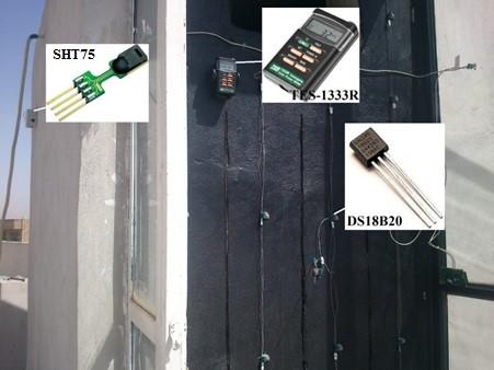
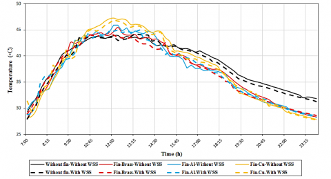
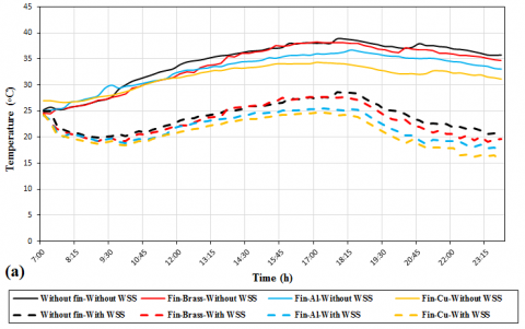
Figure 5 shows the temperature distribution of the absorber. According to the results, the application of the fins at both modes of with or without WSS increased the absorber temperature in the midday, which is resulted by the solar radiation absorbed by the thermal fin transferred to the wall by conduction. At midday until late hours of the day, the absorber temperature reduced because of enhancement of natural convection heat transfer from the Trombe wall. According to the results, due to the low thermal conductivity, brass fin creates the lowest temperature changes on the absorber, and copper fin causes the most changes on the absorber temperature due to its high thermal conductivity. The absorber temperature is lower with WSS than without WSS for all fin types due to flow of air with lower temperature resulting in higher free convection inside the channel.
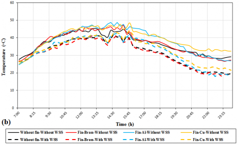
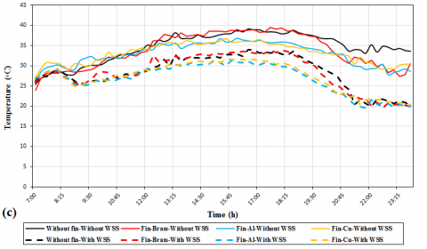
According to the Figure 6, the air temperature inside the channel increases with thermal fins (Figure 6b), which increases the temperature difference between the channel and the room. This enhances the convection heat transfer inside the channel and draws more air flow from the lower vent of the Trombe wall that intensifies the air flow circulation inside the room. Increased air flow decreases the temperature in the room and in the lower vent of the Trombe wall. In addition, with the increase in the conductivity of the fin, the convection heat transfer increases leading to further decrease in the room air temperature.
Table 2. Outdoor conditions for eight consecutive days
|
|
Day- Fin type |
Outdoor temperature (°C) |
Relative humidity (%) |
Average solar heat flux received by absorber (W/m2) |
|
Without WSS |
27 Aug. - Without fin |
30 |
15.2 |
289.4 |
|
28 Aug. - Brass fin |
29.6 |
14 |
292.3 |
|
|
29 Aug. - Aluminum fin |
29.6 |
14.5 |
292.7 |
|
|
30 Aug. - Copper fin |
29.7 |
14.2 |
298.2 |
|
|
With WSS |
31 Aug. - Without fin |
29.8 |
14 |
298.8 |
|
1 Sep. - Brass fin |
29.7 |
15.5 |
304.3 |
|
|
2 Sep. - Aluminum fin |
30 |
14.5 |
304.5 |
|
|
3 Sep. - Copper fin |
30 |
14 |
304.9 |
Figure 5. Absorber temperature variation for different types of fin
Figure 6. Variation of (a) room air temperature, (b) channel air temperature and (c) lower vent air temperature for different fin types
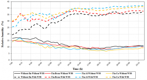
Figure 7 shows the relative humidity changes in the room. As mentioned before, fins increase the convection heat transfer in the channel and the air intake from the lower vent of the Trombe wall into the channel. This increases the indoor air flow and the outdoor air intake from rear vents into the room. Therefore, without WSS, it is significantly affected by the outdoor humidity, and as seen in the figure, the humidity rates are almost close to each other because the outdoor conditions have been almost uniform from August 27th to 30th. In the presence of WSS, the trend is as before, with the difference that when using fins, and with the concurrent increase in the air intake from the back vents of the room, the humidity inside the room also increases. In this case, the higher the heat transfer coefficient or the higher the convection heat transfer and air flow, the greater the relative humidity inside the room.
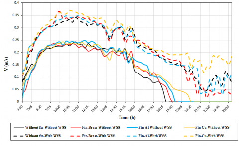
Figure 8 shows the air velocity inside the channel. According to the results, using fin increases the convection heat transfer inside the channel. An increase in the convection heat transfer also enhances the air velocity inside the channel. In addition, the use of WSS resulted in higher air velocity in the channel because of increase of air temperature discrepancy between the room and the channel.
Figure 7. Variation of relative humidity inside the room for different fin types
Figure 8. Air velocity variation in the channel for different fin types
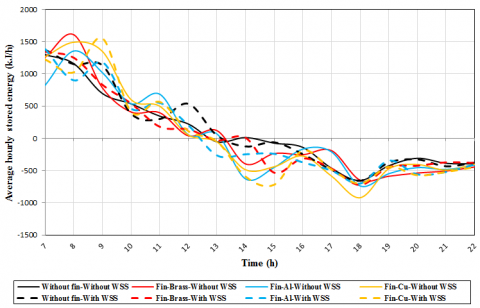
Figure 9. Average stored energy within the Trombe wall for different fin types
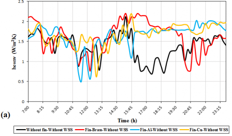
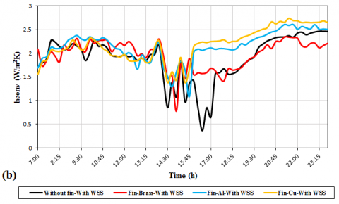
Figure 10. Convective heat transfer coefficient of the absorber for different fin types (a) without WSS and (b) with WSS
Figure 9 shows the average energy stored inside the Trombe wall per hour (Eqns. (1) and (2) [8, 10, 19]). As can be seen from the figure, the fins increase the energy stored in the wall during sunlight, which is due to the fin temperature increase during sunlight and the energy transfer to the Trombe wall absorber. Meanwhile, at the late hours of the day, the average hourly stored energy within the Trombe wall with thermal fins decreases more than the case without thermal fins. In addition, the higher the fin heat transfer coefficient, the higher or the lesser the average hourly stored energy.
$\frac{\Delta E}{\Delta t}=\frac{m_{e} c \Delta T_{o s g}}{\Delta t}=\frac{\rho_{c} \forall c \Delta T_{o s g}}{\Delta t}, \Delta t=t_{t}-t_{t-1}=1$hour (1)
$\Delta T_{\text {avg }}=T_{\text {apg } i}-T_{\text {ovg } i-1}$ (2)
Figure 10 represents the convection coefficient in the absorber. The Rayleigh number is calculated by Eq. (3), the absorber convection coefficient by Eqns. (4) and (5) [10]. As stated previously, the fins increase the heat transfer coefficient inside the channel and this, in turn, increases the Rayleigh number and convection coefficient. Moreover, as the heat transfer coefficient of the fin increases, the Rayleigh number and the convection heat transfer coefficient increase. In addition, with the WSS, due to the increase in the temperature difference between the channel and the room, Rayleigh number and the absorber convection coefficient increase. Use of thermal fins intensifies this increase.
$R a=\frac{g \beta \Delta T H^{3}}{v \alpha}$ (3)
$\begin{array}{l}
\overline{N u_{H}}=0.68+\frac{0.67 R a_{H}^{\frac{1}{4}}}{\left[1+(0.492 / \mathrm{Pr})^{\frac{9}{16}}\right]^{\frac{4}{9}}} \text { Laminar flow } \\
^{9}
\end{array}$ (4)
$\overline{N u_{H}}=\left\{0.825+\frac{0.387 R a_{H}^{\frac{1}{6}}}{\left[1+(0.492 / \operatorname{Pr})^{\left.\frac{9}{16}\right]^{\frac{8}{27}}}\right.}\right\}^{2} \text { Turbulent flow }$ (5)
The amount of heat transferred to the air flow in the channel gap is obtained according to the Eq. (6) [30]:
$\begin{array}{l}
Q_{0}=\dot{m} C_{p f}\left(T_{0}-T_{i}\right) \\
C_{p f}=\left[1.007+0.00004\left(T_{f}-300\right)\right] \times 10^{3}
\end{array}$ (6)
The mean air temperature is calculated from [30]:
$T_{f}=\gamma T_{0}+(1-\gamma) T_{i}$ (7)
In the above equation, γ is the mean temperature approximation coefficient and it was considered equal to 0.74, as proposed by Ong and Chow [31]. Additionally, Ti was taken equal to the room temperature (Tr). Therefore, the useful amount of heat transfer to the air flow can be obtained in terms of the mean and inlet air temperatures, expressed as follows [30]:
$Q_{0}=\dot{m} C_{p f}\left(T_{f}-T_{r}\right) / \gamma$ (8)
In order to measure the useful energy captured by the air flow passing through the channel, a thermal efficiency was introduced. It is calculated in terms of the temperature increase, the air flow rate at the inlet and outlet, and the total heat input, calculated as follows [32]:
$Q_{\text {rot. }}=Q_{0}+Q_{r}$ (9)
Therefore, the cooling efficiency of the system is taken the following form [32]:
$\eta=\frac{Q_{0}}{Q_{0}+Q_{r}}$ (10)
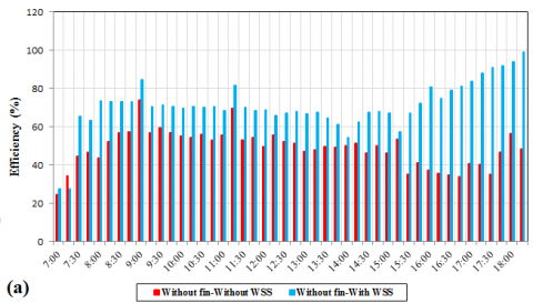
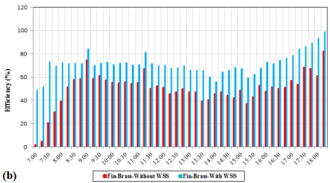
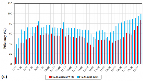
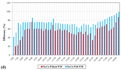
Figure 11 illustrates the cooling efficiency of the system based on Eq. (10). According to the results, with the increase in the natural convection inside the channel, the cooling efficiency increases. The use of WSS increases the discrepancy between the room air temperature and channel air temperature, which increases the natural convection and the cooling efficiency. Increasing the heat transfer coefficient of the fin also increases the natural convection and the cooling efficiency.
Figure 11. Cooling efficiency of the system for (a) without fin, (b) with brass fin, (c) with aluminum fin and (d) with copper fin
3.2 Effect of the number of fins
The effect of the number of fins was investigated between September 5th to 8th and September 13th to 20th 2019. In addition, the effect of using WSS was considered. Similar to the fin type, the outdoor weather conditions for studying the effect of fin number should also be the same on several consecutive days. According to Tables 3 to 5, the weather conditions of the considered days were mostly the same.
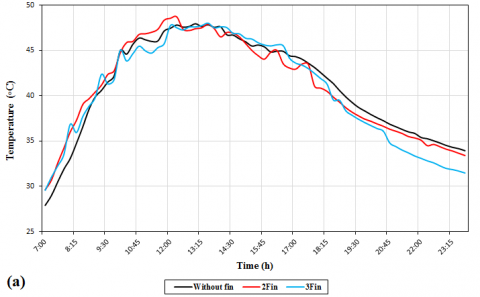
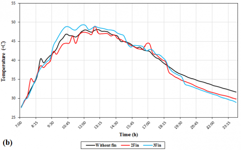
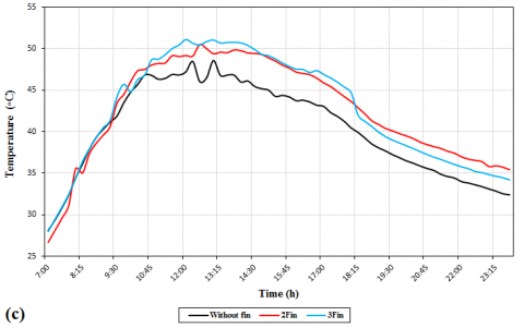
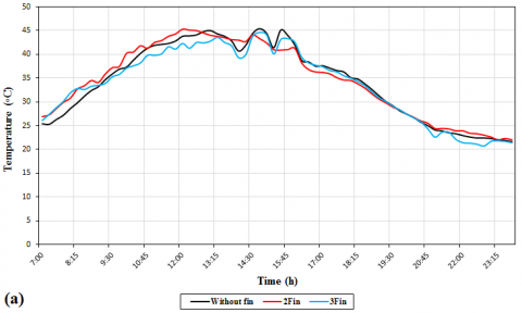
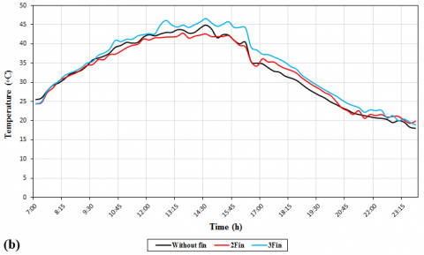
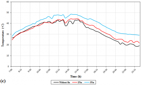
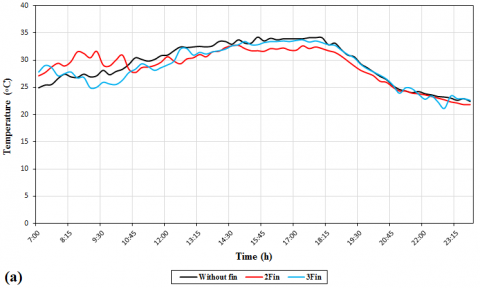
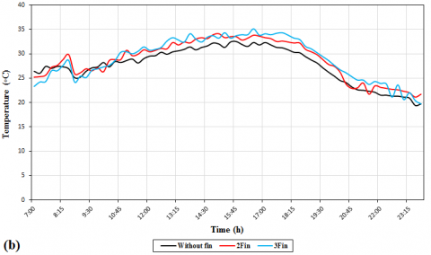
The trend of temperature changes for each fin type resembles the results of Figure 5. As shown in Figure 12a and b, adopting three brass and aluminum fins results in higher absorber temperature at midday than two fins and the without fins. However, in the later hours of the day, it causes further temperature drops. The results of Figure 12c show that using 2 copper fins creates more ideal conditions than using 3 or no fins, because, as shown in the figure, they produce a maximum temperature almost equal that when using 3 fins in the midday and also, a lower temperature reduction than 3 fins in the later hours of the day. In addition, it creates a higher absorber temperature than using no fins in the later hours of the day.
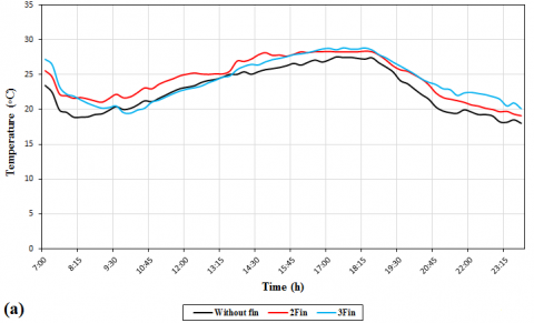
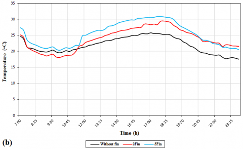
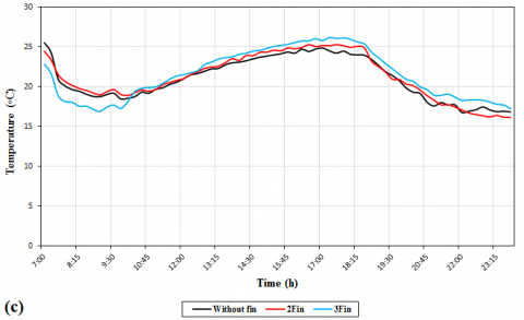
The results of Figures 13 to 15 indicate that the use of fins increases the channel temperature (Figure 14), which increases the temperature difference between the channel and the room. This enhances the convection heat transfer between the air flowing into the channel and the Trombe wall, increasing the air intake from the lower vent of the Trombe wall and its circulation in the room. Furthermore, with an increase in the fin’s thermal conductivity, the convection heat transfer increases and the room temperature further decrease.
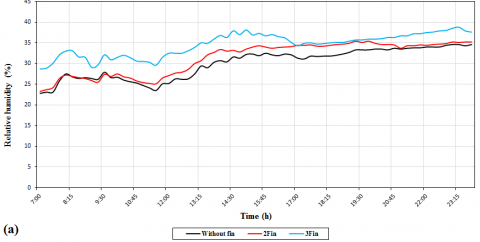
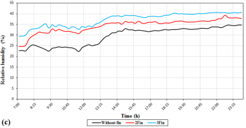
Figure 16 shows the relative humidity changes inside the room. Use of fins increases the indoor air flow and more intake of the ambient air from the back vents into the room, and this, when using WSS, increases the relative humidity. In addition, with the increase in conductivity and the number of fins, due to the increase in the convection heat transfer inside the channel, the relative humidity also increases.
Table 3. Outdoor conditions for brass fin
|
Day- Fin type |
Outdoor temperature (°C) |
Relative humidity (%) |
Average solar heat flux received by absorber (W/m2) |
|
5 Sep. - Without fin |
32.5 |
12.1 |
330.3 |
|
6 Sep. - 2 fins |
32.4 |
11 |
332.5 |
|
8 Sep. - 3 fins |
32.7 |
12.8 |
335 |
Table 4. Outdoor conditions for aluminum fin
|
Day- Fin type |
Outdoor temperature (°C) |
Relative humidity (%) |
Average solar heat flux received by absorber (W/m2) |
|
13 Sep. - Without fin |
30.3 |
11.7 |
356 |
|
14 Sep. - 2 fins |
29.8 |
11.4 |
358.8 |
|
15 Sep. - 3 fins |
29.5 |
10.8 |
361.4 |
Table 5. Outdoor conditions for copper fin
|
Day- Fin type |
Outdoor temperature (°C) |
Relative humidity (%) |
Average solar heat flux received by absorber (W/m2) |
|
17 Sep. - Without fin |
31.6 |
11 |
369.1 |
|
19 Sep. - 2 fins |
31.1 |
12.3 |
388.3 |
|
20 Sep. - 3 fins |
31.4 |
12.5 |
390.2 |
Figure 12. Variation of absorber temperature for (a) brass, (b) Aluminum, and (c) copper fins
Figure 13. Variation of room temperature for the (a) brass, (b) Aluminum, and (c) copper fins
Figure 14. Variation of channel temperature for the (a) brass, (b) Aluminum, and (c) copper fins
Figure 15. Variation of lower vent temperature for the (a) brass, (b) Aluminum, and (c) copper fins
Figure 16. Variation of relative humidity inside the room for the (a) brass, (b) Aluminum, and (c) copper fins
Figure 17. Variation of velocity inside the channel for the (a) brass, (b) Aluminum, and (c) copper fins
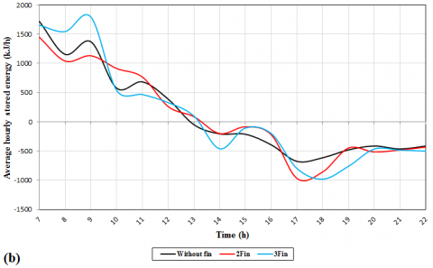
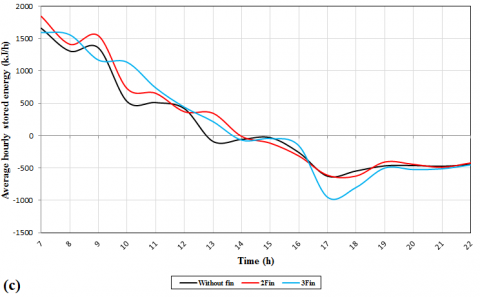
Figure 18. Variation of hourly average stored energy within the Trombe wall for the (a) brass, (b) Aluminum, and (c) copper fins
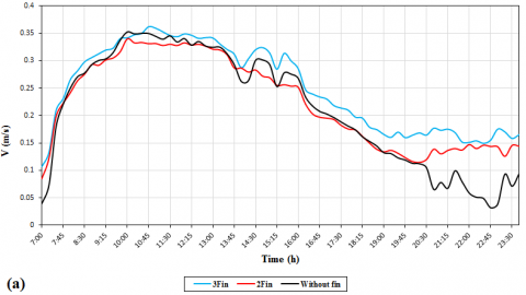
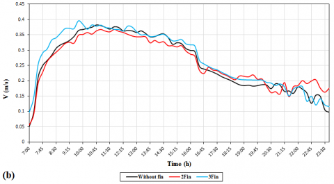
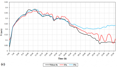
Figure 17 shows the air velocity inside the channel. The trend of velocity changes for different fin materials is as shown in Figure 8. In addition, with the increase in the number of all three types of fins, the air velocity inside the channel increases due to the increase in the natural convection.
Figure 18 shows the average hourly energy stored inside the Trombe wall. The changing trends of the hourly energy stored for various fin materials is the same as in Figure 9. As can be seen from the figure, increasing the number of brass fins in the midday increases the energy stored in the wall due to the warming of fins and increase in the conduction heat transfer from the fin to the wall. Meanwhile, using two aluminum and copper fins stored more energy at midday due to higher thermal conductivity of copper fins and the higher their numbers, the higher the energy transfer to the channel. In the later hours of the day, increasing the number of three fin types caused the hourly stored energy inside the wall to decrease further.
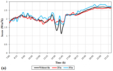
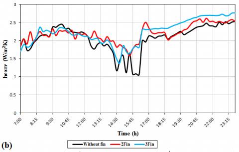
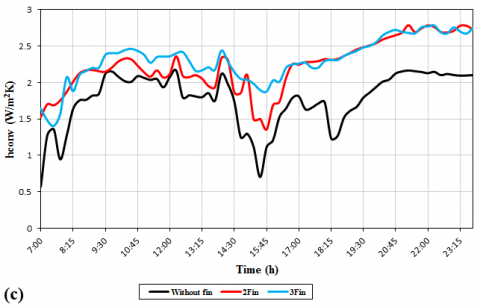
Figure 19 shows the convection coefficient of the absorber inside the channel. As mentioned earlier, increasing the number fins increases the Rayleigh number and the convection coefficient. In addition, as the thermal conductivity of the fin increases, the Rayleigh number and the convection coefficient increase.
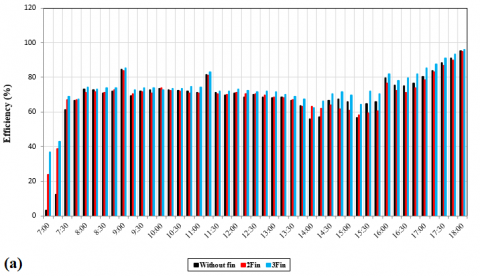
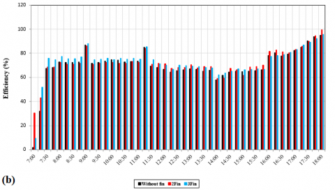
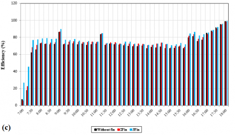
Figure 20 shows the cooling efficiency of the system. The cooling efficiency is increased with increasing natural convection in the channel. According to the figure, the use of fins increases the natural convection and, the cooling efficiency. Furthermore, the increase in the thermal conductivity and the number of fins increases the natural convection and the cooling efficiency.
Figure 19. Variation of hourly average stored energy within the Trombe wall for (a) brass, (b) Aluminum, and (c) copper fins
Figure 20. Variation of cooling efficiency for (a) brass, (b) Aluminum, and (c) copper fins
The results of cooling performance obtained in two sections, including fin type and number of fins, have been discussed. According to the results for the case with and without WSS, Trombe wall temperature variation begins to rise due to absorbing solar radiation and it starts to drop during nighttime due to releasing the stored energy within the Trombe wall to the room (Figure 5). Installing thermal fins on the absorber improved the performance of Trombe wall by receiving and releasing larger amount of solar radiation during daytime and nighttime, respectively. Furthermore, the thermal fin could intensify the heat transfer rate assisting the establishment of natural convection process during both daytime and nighttime (Figures 8, 10).
According to the obtained results, copper and aluminum fins, due to their higher thermal conductivity, transfer larger amount of energy to the Trombe wall and increase the amount of energy stored within the wall. It enabled the system to function longer during nighttime period (Figure 9). Furthermore, copper fin, due to its higher thermal conductivity, increased the convective heat transfer inside the room and channel enhancing the circulation of air in these parts. This led a larger amount of fresh air to be sucked from the vents, located on the rear room wall, into the room that reduces the room air temperature further (Figure 6). Therefore, aluminum and copper fins could create better comfortable conditions due to their capability in increasing the amount of stored energy within the Trombe wall and enhancing the rate of convection heat transfer inside the room and channel (Figure 11). The results showed that the copper fin had the best performance in terms of increasing the Trombe wall temperature, the stored energy, the rate of natural convection ,the cooling efficiency and more decrease of room temperature.
The number of fins also played an important role in absorbing the solar radiation and creating airflow inside the room and channel. By increasing the number of fins, especially copper fins, the amount of stored energy within the Trombe wall increased (Figure 18). Furthermore, increasing the number of fins enhanced the rate of convection heat transfer inside the channel causing larger amount of air to flow through the lower vent of Trombe wall into the channel and consequently the room air temperature reduced (Figures 13, 17, 19). The results also showed that 2 and 3 copper fins create better comfort conditions in terms of indoor air temperature and system cooling efficiency (Figure 20).
In addition, adopting the water spraying system, by creating air temperature difference between the room and channel space, facilitated the air circulation inside the room and the room air temperature decreased largely. According to the results, the cooling efficiency of the system increased around 20% when the water spraying system was used. Therefore, the best performance of the system was achieved when the water spraying system was adopted along with installing 2-3 copper fins on the Trombe wall absorber. It should be noted that the system performance can be further analyzed by changing the shape and arrangement of thermal fins and also using them on the back side of Trombe wall.
This study experimentally studied the effect of three types of rectangular fins on the cooling performance of a new designed Trombe wall combined with solar chimney and WSS. The main difference between the present study and previous researches was applying thermal fins on the absorber of Trombe wall. Furthermore, few studies investigated the cooling performance of the Trombe wall. However, the present work investigated both the effect of thermal fin and new design of Trombe wall channel on the cooling performance of the system and the following experimental results were found:
1. According to the fin type analysis, the average room temperature was about 30-35°C and 20-25°C without and with WSS, respectively. Furthermore, the average relative humidity of the room was around 8-12% and 30-40% without and with WSS for all cases. It implies that the aluminum and copper fins created a similar room air temperature distribution with and without WSS. However, with regard to the system cooling efficiency, copper fins create better indoor condition than the aluminum fins and could be therefore better choice for the cooling application.
2. Regarding the cooling efficiency of the system when the fin number effect is taken into consideration, the average room air temperature was measured around 18-25°C, 22-28°C, and 19-30°C for copper, brass, and aluminum fins, respectively. Furthermore, the average relative humidity was around 30-40%, 25-35%, and 25-36% for copper, brass, and aluminum fins respectively. Similar to fin type analysis, aluminum and copper fins provide the same condition in terms of temperature distribution inside the room. Nevertheless, two and three copper fins create better condition than other cases. Therefore, two and three copper fins could be more desirable for the cooling application.
3. Adopting WSS increases the cooling efficiency around 25%. Moreover, applying thermal fin on the Trombe wall absorber can be considered as potential solution for improving the cooling performance of the Trombe wall, and the copper fin could enhance this effect by 6% more than other fins.
4. In spite of acceptable performance of the system, there are still some issues pending in this study. As the system is very dependent to outdoor conditions, low velocity of air at the incoming fresh airports might not be able to establish a desirable airflow inside the room. Although applying thermal fin on the absorber assisted the Trombe wall in receiving larger amount of solar radiation, it also led a higher thermal heat to be transferred from the channel glasses to the environment during night, which affected the system performance adversely.
5. The system presented in this study can be regarded as a viable solution especially in regions facing extremely high-water stress. The low amount of water needed for WSS can create an acceptable indoor condition in terms of air temperature and relative humidity all day long. Moreover, the system is economical and environmentally friendly, as it does not use any mechanical cooling or heating devices
[1] Hong, X., Leung, M.K.H., He, W. (2019). Thermal behaviour of Trombe wall with venetian blind in summer and transition seasons. Energy Procedia, 158: 1059-1064. https://doi.org/10.1016/j.egypro.2019.01.257
[2] Li, S., Zhu, N., Hu, P., Lei, F., Deng, R. (2019). Numerical study on thermal performance of PCM Trombe Wall. Energy Procedia, 158: 2441–2447. https://doi.org/10.1016/j.egypro.2019.01.317
[3] Briga-Sá, A., Martins, A., Boaventura-Cunha, J., Carlos Lanzinha, J., Paiva, A. (2014). Energy performance of Trombe walls: Adaptation of ISO 13790:2008(E) to the Portuguese reality. Energy and Buildings, 74: 111-119. https://doi.org/10.1016/j.enbuild.2014.01.040
[4] Hami, K., Draoui, B., Hami, O. (2012). The thermal performances of a solar wall. Energy, 39(1): 11-16. https://doi.org/10.1016/j.energy.2011.10.017
[5] Liu, Y., Wang, D., Ma, C., Liu, J. (2013). A numerical and experimental analysis of the air vent management and heat storage characteristics of a trombe wall. Solar Energy, 91: 1-10. https://doi.org/10.1016/j.solener.2013.01.016
[6] Hong, X., He, W., Hu, Z., Wang, C., Ji, J. (2015). Three-dimensional simulation on the thermal performance of a novel Trombe wall with venetian blind structure. Energy and Buildings, 89: 32-38. https://doi.org/10.1016/j.enbuild.2014.12.014
[7] Zhu, J., Chen, B. (2013). Simplified analysis methods for thermal responsive performance of passive solar house in cold area of China. Energy and Buildings, 67: 445-452. https://doi.org/10.1016/j.enbuild.2013.07.038
[8] Rabani, M., Kalantar, V., Dehghan, A.A., Faghih, A.K. (2015). Experimental study of the heating performance of a Trombe wall with a new design. Solar Energy, 118: 359-374. https://doi.org/10.1016/j.solener.2015.06.002
[9] Yilmaz, Z., Kundakci, B.A. (2008). An approach for energy conscious renovation of residential buildings in Istanbul by Trombe wall system. Building and Environment, 43(4): 508-517. https://doi.org/10.1016/j.buildenv.2006.11.033
[10] Rabani, M., Rabani, M. (2019). Heating performance enhancement of a new design trombe wall using rectangular thermal fin arrays: An experimental approach. Journal of Energy Storage, 24: 100796. https://doi.org/10.1016/j.est.2019.100796
[11] Rabani, M., Kalantar, V. (2015). Numerical investigation of the heating performance of normal and new designed Trombe wall. Heat and Mass Transfer, 52(6): 1139-1151. https://doi.org/10.1007/s00231-015-1616-1
[12] Jaber, S., Ajib, S. (2011). Optimum design of Trombe wall system in mediterranean region. Solar Energy, 85(9): 1891-1898. https://doi.org/10.1016/j.solener.2011.04.025
[13] Lin, Y., Ji, J., Zhou, F., Ma, Y., Luo, K., Lu, X. (2019). Experimental and numerical study on the performance of a built-middle PV Trombe wall system. Energy and Buildings, 200: 47-57. https://doi.org/10.1016/j.enbuild.2019.07.042
[14] Wang, W., Tian, Z., Ding, Y. (2013). Investigation on the influencing factors of energy consumption and thermal comfort for a passive solar house with water thermal storage wall. Energy and Buildings, 64: 218-223. https://doi.org/10.1016/j.enbuild.2013.05.007
[15] Rabani, M., Kalantar, V., Faghih, A.K., Rabani, M., Rabani, R. (2013). Numerical simulation of a Trombe wall to predict the energy storage rate and time duration of room heating during the non-sunny periods. Heat and Mass Transfer, 49(10): 1395-1404. https://doi.org/10.1007/s00231-013-1175-2
[16] Zalewski, L., Joulin, A., Lassue, S., Dutil, Y., Rousse, D. (2012). Experimental study of small-scale solar wall integrating phase change material. Solar Energy, 86(1): 208-219. https://doi.org/10.1016/j.solener.2011.09.026
[17] Zhu, N., Li, S., Hu, P., Lei, F., Deng, R. (2019). Numerical investigations on performance of phase change material Trombe wall in building. Energy, 187: 116057. https://doi.org/10.1016/j.energy.2019.116057
[18] Chen, W., Liu, W. (2008). Numerical analysis of heat transfer in a passive solar composite wall with porous absorber. Applied Thermal Engineering, 28(11-12): 1251-1258. https://doi.org/10.1016/j.applthermaleng.2007.107
[19] Rabani, M., Kalantar, V., Dehghan, A.A., Faghih, A.K. (2015). Empirical investigation of the cooling performance of a new designed Trombe wall in combination with solar chimney and water spraying system. Energy and Buildings, 102: 45-57. https://doi.org/10.1016/j.enbuild.2015.05.010
[20] Long, J., Jiang, M., Lu, J., Du, A. (2019). Vertical temperature distribution characteristics and adjustment methods of a Trombe wall. Building and Environment, 165, 106386. https://doi.org/10.1016/j.buildenv.2019.106386
[21] Rabani, M., Kalantar, V., Rabani, M. (2019). Passive cooling performance of a test room equipped with normal and new designed Trombe walls: A numerical approach. Sustainable Energy Technologies and Assessments, 33: 69-82. https://doi.org/10.1016/j.seta.2019.03.005
[22] Hong, X., Leung, M.K.H., He, W. (2019). Effective use of venetian blind in Trombe wall for solar space conditioning control. Applied Energy, 250: 452-460. https://doi.org/10.1016/j.apenergy.2019.04.128
[23] Stazi, F., Mastrucci, A., di Perna, C. (2012). Trombe wall management in summer conditions: An experimental study. Solar Energy, 86: 2839-2851. https://doi.org/10.1016/j.solener.2012.06.025
[24] Soussi, M., Balghouthi, M., Guizani, A. (2013). Energy performance analysis of a solar-cooled building in Tunisia: Passive strategies impact and improvement techniques. Energy and Buildings, 67: 374-386. https://doi.org/10.1016/j.enbuild.2013.08.033
[25] Wongwuttanasatian, T., Sarikarin, T., Suksri, A. (2020). Performance enhancement of a photovoltaic module by passive cooling using phase change material in a finned container heat sink. Solar Energy, 195: 47-53. https://doi.org/10.1016/j.solener.2019.11.053
[26] Micheli, L., Reddy, K.S., Mallick, T.K. (2015). Plate micro-fins in natural convection: an opportunity for passive concentrating photovoltaic cooling. Energy Procedia, 82: 301-308. https://doi.org/10.1016/j.egypro.2015.12.037
[27] Grubišić-Čabo, F., Nižetić, S., Čoko, D., Marinić Kragić, I., Papadopoulos, A. (2018). Experimental investigation of the passive cooled free-standing photovoltaic panel with fixed aluminum fins on the backside surface. Journal of Cleaner Production, 176: 119-129. https://doi.org/10.1016/j.jclepro.2017.12.149
[28] Deng, H., Liu, J., Liu, M. (2020). Numerical investigation on complete condensation and freezing of finned tube air-cooled condensers. Applied Thermal Engineering, 168. https://doi.org/10.1016/j.applthermaleng.2019.114428
[29] Vittorini, D., Cipollone, R. (2019). Fin-cooled photovoltaic module modeling – Performances mapping and electric efficiency assessment under real operating conditions. Energy, 167: 159-167. https://doi.org/10.1016/j.energy.2018.11.001
[30] Bansal, N.K., Mathur, J., Mathur, S., Jain, M. (2005). Modeling of window-sized solar chimneys for ventilation. Building and Environment, 40: 1302-1308. https://doi.org/10.1016/j.buildenv.2004.10.011
[31] Ong, K.S., Chow, C.C. (2003). Performance of solar chimney. Solar Energy, 74: 1-17. https://doi.org/10.1016/S0038-092X(03)00114-2
[32] Li, Y., Liu, S. (2014). Experimental study on thermal performance of a solar chimney combined with PCM. Applied Energy, 114: 172-178. https://doi.org/10.1016/j.apenergy.2013.09.022