Yoalbys Retirado-Mediaceja* | Yanán Camaraza-Medina | Andrés A. Sánchez-Escalona | Héctor L. Laurencio-Alfonso | Marcelo F. Salazar-Corrales | Carlos Zalazar-Oliva
© 2020 IIETA. This article is published by IIETA and is licensed under the CC BY 4.0 license (http://creativecommons.org/licenses/by/4.0/).
OPEN ACCESS
In this work, was made a thermo-exergy evaluation of four steam boilers that are used in the thermoelectric power plant belong to a Cuban productive company, which, have not been sufficiently studied from the energy point of view. The methodology for the estimation of the thermal and exergy efficiency values of these facilities is established and systematized in an algorithm. For this purpose, in this paper the GOST method is used in the assess evaluation of the steam boilers (direct and indirect method). The final results show a high correspondence between the gross thermal efficiency values obtained by the direct and indirect methods, their difference does not exceed 2.7% in the 87.5% of each variant calculated and the average value was 1.89%. The use of the thermal energy and the exergy in the boilers compute values near of 90.14 and 46.42% respectively. The application of proposal procedure shows a favorable behavior of the facilities object of study in this paper.
performance, thermal, exergetic, efficiency, boilers
The steam execute an essential role in the energy transportation for different industrial applications, therefore, results necessary to obtain it with the bigger possible efficiency (energetics, economic and ecological). Cuba is a nation in the process of development, but, with limitations in the energy availability and reduced funds to get it. The systematic evaluation of thermo-exergetic efficiency of the steam boilers is a priority in the companies of Cuba, due to the strategic role and the high economic and environmental cost associated to the process of steam generation [1].
In the Thermoelectric Power Plants (CTE), the steam boilers acquire a bigger importance due to their bigness, productivity and fuel consumption [2, 3]. The steam boilers analyzed in this paper (boilers 2, 4, 5 and 6), belong to a CTE associated to a mining industry, where, the first guarantees the heat energy, the processed water, the CO2 and a part of the electric power required by the industry.
The used water, its pureness, temperature and pressure, constitute an important elements, to guarantee the efficient operation and the thermo-exergetic efficiency analysis of this facilities[4]. Also, come to be relevant the vapor and his quality, fuel and their properties, the air excess, The volumetric flows of air and combustion gases, this last element generate fouling and corrosion on the heat transfer surface, reducing their efficiency [5].
Classical literature contains a theoretical satisfactory support for the thermo-exergetic evaluation of the investigated steam boilers and discusses subjects of importance for the present study: methodologies for the thermal calculation of facilities and boilers aggregates [6], exploitation and constructive materials used in its manufacturing [7] and methodologies for thermo-exergetic efficiency assessment [8, 9].
Equally, in the literature are found specific investigations that discuss important aspects related with the boilers. The paper [10] is develops a methodology for the simulation of steam production systems and depuration of SO2 and NOX, proposing besides the uses of the simulator SIMCOMB in the calculation of the systems efficiency, because he makes possible the analysis for different fuels. Other researches implement with success the classical methods (direct and indirect) for the heat balance of boilers [11-13], and mathematical modelation of the classical methods [14, 15], which proves to be an innovative contribution that has spread out of late years.
The exergetic balance has equally been object of study, analyzing an steam boiler (coupled to an CTE of 350 MW), operating under four loads conditions, 100, 75, 50 and 25%. In this study a exergetic model was realized considering the boiler as an control volume, being confirmed that the generation of irreversibilities reaches a maximum when the boiler is operated to lower loads (50 and 25%) [16].
Krasniqi-Alidema et al. [17] were developed an optimization model for to determine the exergy dissipation in the different facilities of the studied CTE, concluding that the bigger destruction of exergy happens in the steam boiler, due to the irreversibility in the combustion process and the heat transfer between gases and the water-vapor flow [17]. Other investigations with similar contributions to the state of art are developed by Fernández-Conde et al. [18, 19].
Literature has orientated investigations to increment the energy efficiency of the facilities, from the introduction of geometric modifications in the boiler's nozzles for to increase the efficient combustion of the heavy fuel oil [20]. Other researches include the development of more efficient methods for the failures diagnostic [21], the optimization of the shell to keep the vapor properties [22] and the energetic optimization applying a system of energy management, based in the standard ISO5000 [23].
As it is appreciated, they are known researches that discuss the energetic diagnostic of steam boilers in the industrial sector and the CTE. In Cuba, however, boilers object of study has not been evaluated by a thermo-exergetic analysis for the present conditions of operation, this important aspect constitutes the principal objective of this paper.
2.1 Initial considerations
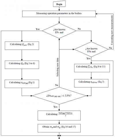
In the thermo-exergetic evaluation of the steam boilers, are used the direct and indirect methods for to accomplish the thermal balance, and complement the thermal analysis with the exergy balance. The methodology used in this work is available in the consulted sources [24-27]. Nevertheless, in this investigation comes to be innovative the systematization of the preceding procedures in an algorithm, (see the Figure 1) and the adjustment to the specific characteristics of the studied boilers (see later epigraphs 2.1-2.4). The given algorithm detailed how will be executed the thermo-exergetic evaluation of the analyzed steam boilers.
2.2 Heat balance: Direct method
The direct method consists in to measure an group of operation parameters into the steam boilers and with them, to determine the gross thermal efficiency of the facilities, by means of the Equation (1) [28, 29].
$\eta_{t G V_{M D}}=100 \cdot \frac{Q_{u t i l}}{Q_{d} \cdot B}$ (1)
In Equation (1) $\eta_{t G V_{M D}}$ is the gross thermal efficiency of the boiler, obtain by means of the direct method, in %. $Q_{\text {util}}$ is the useful heat, in kJ/h. $Q_{d}$ is the available heat, in kJ/h and B is the fuel consumption, in kg/h.
The useful heat $Q_{u t i l}$ is obtained with Equation (2), which, it is adjusted to the boilers object of study. Only it is produced superheated vapor, wet steam is not extracted, there are no vapor reheating, neither additional heatings [30].
$Q_{\text {util}}=D_{\text {vsc}} \cdot\left(i_{\text {vsc}}-i_{\text {aa}}\right)$ (2)
In Equation (2) $D_{v s c}$ is the superheated steam rate, in kg/h. $i_{v s c}$ and $i_{a a}$ are the superheated steam and supply water enthalpies, in kJ/kg.
The available heat $Q_{d}$ is obtained with the Equation (3), it is recommended when the air does not preheating in the steam boiler [4].
$Q_{d}=Q_{b}+Q_{f c}+Q_{a t m}$ (3)
where,
$\begin{array}{c}
Q_{b}=339.2 \cdot C+1030.4 \cdot H-108.9 \cdot(0-S)-25.14 \\
\cdot W
\end{array}$ (4)
$Q_{f c}=t_{c} \cdot\left(1.737+0.0025 \cdot t_{c}\right)$ (5)
$Q_{a t m}=D_{V a t m} \cdot\left(i_{V a t m}-i_{V s g v}\right)$ (6)
In Equation (4) C, H, O, S, W represent respectively elementary composition of the fuel, (carbon, hydrogen, oxygen, sulphur and water content expressed in % by mass). In Equations (3) to (6) $Q_{b}$ is the lower heating value, in kJ/kg. $Q_{f c}$ is the physical heat of the fuel at the burners input, in kJ/kg. $Q_{a t m}$ is the heat introduced by the vapor of atomization, in kJ/kg. $t_{c}$ is the fuel oil temperature, in $^{\circ} \mathrm{C} . D_{V a t m}$ is the vapor rate used in the atomization, in (kg vapor/kg fuel oil). $i_{V a t m} \text { and } i_{V s g v}$ are the entalphy of the atomization vapor and the vapor in the boiler outlet, in kJ/kg. For to obtain $D_{V a t m}$ is recomended to apply the relations given in the Table 1.
Table 1. Recomended values of $D_{V a t m}$
|
Steam boiler use |
$D_{V a t m}$ |
|
CTE |
$(0.02 \cdots 0.1)$ |
|
Industrial facilities |
$(0.1 \cdots 1)$ |
2.3 Heat balance: Indirect method
This method makes possible identifying and determining the present value of the heat losses in the boilers, and with these, the gross thermal efficiency of the steam boilers is calculated, through the Equation (7) [31-33].
$\eta_{i G V m i}=100-\sum q_{n}$ (7)
where,
$\sum q_{n}=q_{2}+q_{3}+q_{4}+q_{5}+q_{6}+q_{7}$ (8)
In Equation (7) $\eta_{i G V m i}$ is the gross thermal efficiency of the boiler obtains by means of the indirect method, in %. In Equation (8) all used terms are given in %. $q_{2}$ is the heat loss in the exhaust gases, $q_{3}$ and $q_{4}$ are the losses due to the chemical and mechanical incombustibility respectively, $q_{5}$ is the heat loss by heat transfer to the environment, $q_{6}$ and $q_{7}$ are the heat losses due to the residues extracted from the furnace and the purge extractions respectively.
The heat losses $\left(q_{2}, q_{3}, q_{5}, q_{7}\right)$ are calculated with the Equations given by the work [30]. The losses due to mechanical incombustibility and the residues extracted from the furnace $\left(q_{4} \approx q_{6} \approx 0\right)$ because the steam boiler evaluated uses fuel oil [34]. Gases get out of the boilers to high temperatures and drag along a great quantity of heat to the atmosphere, this loss $\left(q_{2}\right)$ is determined as:
$q_{2}=\frac{\left(i_{s g v}-\alpha \cdot i_{a i r e}\right) \cdot\left(100-q_{4}\right)}{Q_{d}}$ (9)
where,
$\alpha=\frac{N_{2}}{N_{2}-3.76 \cdot\left(O_{2}-0.5 \cdot C O-0.5 \cdot H_{2}-2 \cdot C H_{4}\right)}$ (10)
$N_{2}=100-\left(C O+R O_{2}+O_{2}+H_{2}+C H_{4}\right)$ (11)
In Equations (9) to (11) $i_{s g v}$ and $i_{a i r e}$ are the enthalpies of the exhaust gases at the steam boiler outlet and the theoretical air respectively, in kJ/kg. $\alpha$ is the air excess coefficient (dimensionless). $\left(N_{2}, O_{2}, C O, H_{2}, R O_{2}, C H_{4}\right)$ are the volumes of nitrogen, oxygen, carbon monoxide, hydrogen, triatomic gases and methane in the dry gases, measured in the point of the boiler where is necesary to know the required coefficient of air excess; in %.
The steam boliers analized in this paper, in the combustion gases not found emissions of hydrogen and methane, therefore, in the thermo-exergetic evaluation was considered that $H_{2}=C H_{4}=0$.
Losses for chemical incombustibility are obtanied as:
$\begin{array}{c}
q_{3}=\frac{126.4 \cdot C 0+108 \cdot H_{2}+358.1 \cdot C H_{4}}{Q_{d}} V_{g s} \\
\cdot\left(100-q_{4}\right)
\end{array}$ (12)
where,
$V_{g s}=\frac{1.86 \cdot(C+0.375 \cdot S)}{R O_{2}+C O+C H_{4}}$ (13)
In the Equation (13) $V_{g s}$ is the volume of dry gases, in m3N/kg.
Figure 1. Systematization algorithm of the proposal methodology
In Figure 1, $F P_{V}$ are the flow rate and thermochemical properties of the superheated steam, atomization vapor and supply water. $F P_{C}$ are the flow and thermochemical properties of the fuel (include the elementary composition). $F P_{G}$ are the flow, chemical composition and thermochemical properties of the combustion gases and the air. $F P_{e}$ are the flow and thermochemical properties of the purge extractions.
The energy losses due to the heat transfer from the steam boiler to the environment, consider the simultaneous effect of the radiation, conduction and convection, through the apertures, walls, bottom and top of the boiler. These losses can be obtained by:
$q_{5}=q_{5 D n} \cdot \frac{D_{v s c N}}{D_{v s c R}}$ (14)
In Equation (14) $q_{5 D n}$ is the relation between the heat losses by radiation and the heat production in the boiler, in %. $D_{\text {vscN}}$ and $D_{v s c R}$ are the nominal and real boiler production of superheat steam, in kg/h.
The heat losses due to purge extractions can be obtained as:
$q_{7}=100 \cdot \frac{G_{e} \cdot i_{e}}{Q_{d} \cdot B}$ (15)
In Equation (15) $G_{e}$ is the rate of purge extractions, (see Table 2). $i_{e}$ is the enthalpy of the purge extractions, en kJ/kg.
Table 2. Recomended values of $G_{e}$
|
Steam boiler use |
$G_{e}$ |
|
CTE |
$(0.003 \cdots 0.03) \cdot D_{\text {vsc}}$ |
|
Industrial facilities |
$(0.02 \cdots 0.07) \cdot D_{v s c}$ |
2.4 Airflows and gases of combustion
The airflow to the boiler is supplied by the forced draft fan (VTF), while, the combustion gases are evacuated by the induced draft fan (VTI). These rate flow values can be obtained as:
$m_{a}=\beta_{1} B V_{a} \alpha \cdot\left[\frac{T_{a f}+273.15}{273.15}\right] \cdot \frac{1.01 \times 10^{5}}{h_{b}}$ (16)
$\begin{array}{c}
m_{g}=\beta_{1} B\left[V_{g}+(\alpha-1) \cdot V_{a}\right] \cdot\left[\frac{T_{g}+273.15}{273.15}\right] \\
\cdot \frac{1.01 \times 10^{5}}{h_{b}}
\end{array}$ (17)
In Equations (16) and (17) $m_{a}$ and $m_{g}$ is the flow rate delivered by VTF and VTI respectively, in m3/s. $\beta_{1}$ is a safety factors for reserve, $(1.02 \cdots 1.05) \cdot T_{a f}$ is the air temperature at VTF inlet, in $^{\circ} \mathrm{C} . T_{g}$ is the temperature of the combustion gases at VTI inlet, in $^{\circ} \mathrm{C} \cdot \alpha$ is the air excess coefficient (dimensionless). $V_{a}$ is the theoretical volume required of dry air, in $\mathrm{m}^{3} \mathrm{N} / \mathrm{kg} . V_{g}$ is the theoretical total volume of gases, in $\mathrm{m}^{3} \mathrm{N} / \mathrm{kg} \cdot h_{b}$ is the barometric air pressure, in Pa.
The theoretical dry air volume $V_{a}$ can be obtained as:
$V_{a}=0.0889 \cdot(C+0.375 \cdot S)+0.265 H-0.03330$ (18)
The theoretical total volume of gases $V_{g}$ can be obtained as:
$V_{g}=V_{g s}+V_{a}$ (19)
2.5 Exergy balance
The exergy efficiency in a steam boiler is obtained as:
$\eta_{e x G V}=100 \cdot E_{R} / E_{E}$ (20)
$\gamma_{e x c V}=100-\eta_{e x} c v=100 \cdot E_{p} / E_{E}$ (21)
In Equations (20) and (21) $\eta_{e x G V}$ is the exergy efficiency of the steam boiler, in%. $\gamma_{e x G V}$ is the magnitude of the exergy loss, in $\% . E_{R}, E_{E} \text { and } E_{P}$ are the recovered, used and lost exergy, in J/s.
Recovered and lost exergy are considered, which depend on the flows of fuel, air, superheated steam, supply water and combustion gases. One last very important element is the combustion process.These exergy values are calculated for each rate flow (vapor, water, air and gases) and for the combustion heat.
2.6 Operation parameters of the boilers
During six weeks were taken 24 daily measurements (every one hour) of the main operation parameters of the four boilers studied, and was determined the average value per week, which corresponds to every one of the analyzed variants (V-1, ..., V-6). Boilers 2, 4 and 5 have similar design characteristics and time of operation and, at present, their operation parameters not defer significantly, for this motive and reasons space, in this paper only are given the selected data for boilers 2 and 6, because they have different design parameters (see Tables 3 and 4), as well as the chemical composition of the used fuel (see Table 5).
Table 3. Operation parameters measured in selected boilers
|
(Boiler 2) |
V-1 |
V-2 |
V-3 |
V-4 |
V-5 |
V-6 |
|
Dvsc(t/h) |
56.9 |
54.6 |
50.2 |
51.6 |
55.1 |
54.9 |
|
Pvsc(MPa) |
3.6 |
3.8 |
3.6 |
3.6 |
3.6 |
3.6 |
|
Tvsc(ºC) |
432.9 |
422.9 |
431.1 |
425.8 |
419.3 |
418.4 |
|
Taa (ºC) |
142.6 |
140.0 |
137.5 |
142.5 |
144.2 |
142.9 |
|
Tc (ºC) |
138.1 |
137.7 |
140.8 |
141.4 |
130.0 |
131.7 |
|
Tgsc (ºC) |
248.3 |
244.2 |
227.4 |
230.9 |
228.3 |
233.0 |
|
Taf (ºC) |
31 |
33 |
30 |
32 |
31 |
30 |
|
B (t/h) |
4.6 |
4.4 |
4.0 |
4.1 |
4.3 |
4.3 |
|
|
||||||
|
(Boiler 6) |
V-1 |
V-2 |
V-3 |
V-4 |
V-5 |
V-6 |
|
Dvsc (t/h) |
115.5 |
118.8 |
117.7 |
106.5 |
107.2 |
111.6 |
|
Pvsc (MPa) |
3.5 |
3.6 |
3.5 |
3.5 |
3.5 |
3.6 |
|
Tvsc (ºC) |
439.5 |
439.3 |
439.8 |
439.5 |
439.5 |
439.5 |
|
Taa (ºC) |
142.3 |
140.8 |
143.1 |
143.4 |
143.2 |
136.8 |
|
Tc (ºC) |
139.5 |
141.9 |
144.2 |
140.4 |
135.9 |
137.5 |
|
Tgsc (ºC) |
296.4 |
297.2 |
293.8 |
286.2 |
280.4 |
289.8 |
|
Taf (ºC) |
31 |
33 |
30 |
32 |
32 |
30 |
|
B (t/h) |
9.3 |
9.6 |
9.5 |
8.6 |
8.6 |
9.1 |
In Table 3 $P_{v s c}$ and $T_{v s c}$ are pressure and temperature of the superheated steam. $T_{a a}, T_{c} \text { and } T_{g s c}$ are respectively the temperatures of supply water, fuel oil and combustion gases at boiler outlet.
In the heat balances (thermal and exergy) of the steam boilers, was used the software Mathcad15 and some software applications (SIMCOMB and Steam Table). Furthermore, were checked the thermochemical properties of water and vapor, ashes, air and combustion gases [35, 36].
Table 4. Chemical composition of the combustion gases, %
|
Variant |
Boiler 2 |
Boiler 6 |
||||
|
CO2 |
O2 |
CO |
CO2 |
O2 |
CO |
|
|
V-1 |
15.6 |
2.5 |
0.10 |
14.4 |
2.6 |
0.010 |
|
V-2 |
15.9 |
2.4 |
0.11 |
14.3 |
2.8 |
0.015 |
|
V-3 |
15.2 |
2.5 |
0.14 |
14.3 |
2.8 |
0.010 |
|
V-4 |
15.1 |
1.8 |
0.10 |
14.02 |
2.7 |
0.010 |
|
V-5 |
15.9 |
2.3 |
0.15 |
13.98 |
3.2 |
0.015 |
|
V-6 |
15.2 |
2.7 |
0.13 |
14.40 |
2.4 |
0.010 |
Table 5. Chemical composition of the fuel oil, %
|
Variant |
C |
H |
O |
S |
N |
W |
|
V-1 |
84.10 |
7.73 |
0.6 |
6.52 |
0.2 |
0.8 |
|
V-2 |
83.91 |
7.71 |
0.6 |
6.48 |
0.2 |
0.8 |
|
V-3 |
83.51 |
7.69 |
0.7 |
6.47 |
0.2 |
0.8 |
|
V-4 |
83.67 |
7.68 |
0.6 |
6.51 |
0.2 |
0.8 |
|
V-5 |
83.95 |
7.59 |
0.7 |
6.49 |
0.2 |
0.8 |
|
V-6 |
83.66 |
7.61 |
0.6 |
6.43 |
0.2 |
0.8 |
3.1 Summary of the main obtained results
The thermal efficiencies values (89.736%, 91.0% and 90.706%) and exergetic efficiencies values (46.238%, 46.709% and 40.83%) obtained for boiler 2, 4 and 5 are very similar (see Table 6). The air excess required by the boilers for his operation under the analyzed conditions showed a variation between 11.8 to 13.3%. Furthermore, the maximum values found were 7.9% for heat loss in the exhaust gases, 0.6% for chemical incombustibility, 2.7 for heat loss for heat transfer to the environment and 1.2% for heat losses due to the residues extracted from the furnace and the purge extractions.
Table 6. Average values of the parameters calculated
|
Calculated values |
$\alpha$ |
$q_{2}(\%)$ |
$q_{3}(\%)$ |
$q_{5}(\%)$ |
$q_{7}(\%)$ |
$\sum q_{n}(\%)$ |
|
GV-2 |
1.118 |
7.817 |
0.421 |
1.831 |
1.092 |
11.161 |
|
GV-4 |
1.132 |
6.189 |
0.523 |
1.907 |
1.103 |
9.722 |
|
GV-5 |
1.133 |
5.929 |
0.537 |
2.635 |
1.100 |
10.201 |
|
GV-6 |
1.142 |
9.975 |
0.044 |
1.048 |
1.074 |
12.141 |
|
Average values |
1.131 |
7.477 |
0.381 |
1.855 |
1.092 |
10.805 |
|
|
||||||
|
Calculated values |
$m_{a}$ $\left(10^{4} \frac{m^{3}}{h}\right)$ |
$m_{g}$ $\left(10^{4} \frac{m^{3}}{h}\right)$ |
$\eta_{t G V_{M D}}$ (%) |
$\eta_{t G V_{m i}}$ (%) |
$\eta_{t G V_{P}}$ (%) |
$\eta_{e x G V}$ (%) |
|
GV-2 |
5.408 |
9.540 |
90.633 |
88.839 |
89.736 |
46.238 |
|
GV-4 |
5.241 |
8.499 |
91.721 |
90.278 |
91.000 |
46.709 |
|
GV-5 |
4.201 |
6.703 |
91.613 |
89.799 |
90.706 |
46.830 |
|
GV-6 |
11.755 |
22.946 |
90.400 |
87.859 |
89.130 |
45.893 |
|
Average values |
6.651 |
11.922 |
91.091 |
89.195 |
90.142 |
46.417 |
In Table 6 $\eta_{t G V_{P}}$ is the bolier average eficciency. This value is the average of the values obtained with the use of the direct and indirect methods.
The results given previously allow asserting that the steam boilers analyzed have adequate thermal efficiencies, in spite of having been more of 25 years of operation. However, the steam boilers analyzed are used only in determined periods (depend of the productive company and his process requirements), which is an important element to consider in the thermal evaluation.
Boilers 6 show an evident deterioration of operation parameters. Current values of production, pressure and temperature of superheated steam results evidence a deterioration of their parameters of functioning. The values of production, pressure and steam temperature are inferior in 37.226 t/h, 0.367 MPa and 0.483 $^{\circ} \mathrm{C}$ respectively, while the nominal capacities are 150 t/h, 3.9 MPa and 440 $^{\circ} \mathrm{C}$ .
The previously addressed, united to the influence of other process variables, limit the quantity and quality of the vapor delivered to the turbines, influence on thermo-exergetic efficiencies of the CTE and the productive steam facilities. In the boiler 6, the thermal and exergetic efficiencies were equal to 89.13 and 45.893% respectively. The thermal efficiency obtained in this study is lower in 3.87 % with respect to the nominal value established by the boiler manufacturer [37].
When jointly analyzing the results obtained, it is inferred that the steam generation system, SGV, (the four boilers together) works with a satisfactory thermal performance (90.142%), despite the fact that the boilers work under operating conditions that differ significantly with the design especifications. However, its exergetic efficiency is low (46.417%). These aspects will be analyzed in more detail in the following sections.
3.2 Excess air coefficient
The excess air coefficient practically have influence over in all the performance indicators of the boilers, because it is who determines the combustion efficiency. In the made study was found that the excess air is located between 8.6 and 17% in its extreme values, but in general the variation showed stability between 10.7 and 15% (see Figure 2).
Figure 2. Excess air coefficient
In boilers (2, 4 and 5) the combustion process was developed with an appropriate excess air (up to 15%, with average values of 11.8, 13.2 and 13.3%). This may be associated with the experience that the operators have in working with this equipment and the reduced steam flows that were obtained in them (53.883, 52.083 and 41.466 t/h), which does not demand excessive amounts of air for combustion. The average fuel consumption was 4.283, 4.1 and 3.266 t/h respectively.
In contrast, boiler 6 demanded an air excess located between 12.1 and 17% (14.2%, average value), which can be attributed to the fact that 122.883 t/h were produced in this installation and consumed 9.12 t/h of fuel oil. Furthermore, it presents significant differences in the supply of air and gas evacuation system, compared to the boilers aforementioned (2, 4 and 5).
In general, the behavior of the excess air coefficient is adequate for these boilers types, because in the combustion of liquid fuels the specialized literature recommends an air excess between 3 and 15%, an aspect that is met in installations in almost all the variants analyzed [38].
3.3 Flow of air and combustion gasses
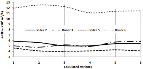
Flows of air and combustion gasses determine the selection of fans, (forced and induced draft), used for the air supply and the gases evacuation in steam production facilities. The transferred air and gas flows have a great influence on the combustion, heat transfer and gross and net thermal efficiencies of the steam boilers, because they influence the electrical energy consumption of the fans and other important auxiliary equipment (pumps for supply pumps and fuel).
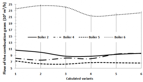
In the boiler 6 these flows were higher by 6.805 and 14.699 m3/h (on average), compared to those obtained in GV- 2, 4 and 5 (see Figures 3 and 4). This behavior can be attributed to the notable difference they have in the steam productivity, fuel consumption and gas temperature at the steam boiler outlet (see Dvsc , B and Tgsc in Table 3). The fans meet the demands for air supply and for the evacuation of the combustion gases, which positively impacts the gross thermal efficiency of the SGV (90.142%). However, the net thermal performance will be conditioned by the fact that boilers 2, 4 and 5 use two fans (VTF and VTI) and the GV-6 only has one installed (the VTF), because the former have a balanced hearth and the second a pressurized furnace.
Figure 3. Supplied airflows by VTF facilities
Figure 4. Gases flow evacuated by VTF facilities
3.4 Heat losses
The heat losses have a high influence on the gross thermal efficiency of the steam boilers, obtained by the indirect method. For the facilities under study, all the heat losses described in the materials and methods section $\left(q_{2}, q_{3}, q_{4}, q_{5}, q_{6}, q_{7}\right)$ were analyzed, but this section only details the behavior of the one that occurs through the exhaust gases $q_{2}$ for constituting the most incident and the highest value in the steam boilers [4].
Boilers 2, 4 and 5 had heat losses through the exhaust gases $q_{2}$ that did not exceed 8.4% (see Figure 5), which constitutes satisfactory behavior despite the inappropriate operating conditions to which they are subjected (poor quality fuel and with high sulfur content, deteriorated auxiliary equipment, insufficient maintenance, among others). In the GV-6, the $q_{2}$ values are located between 9.513 and 10.228% (with 9.975%, as an average value). These values are high for this steam boiler, which is designed to work with a 92-93% gross thermal efficiency at partial loads (110, 80 and 50% of the $D_{\text {vscN}}$) and under nominal conditions [39].
Figure 5. Heat losses $q_{2}$
When evaluating the heat losses due to chemical incombustibility $q_{3}$ and with the extractions $q_{7}$, it is inferred that these did not significantly influence the gross thermal performance, as their values, for the steam generation system (all boilers), were 0.381 and 1.092%. The loss by heat transfer to the environment $q_{5}$ reached 1.855%. It was conditioned by the low productivity of steam and the work at partial loads of the equipment [boilers 2, 4 and 5 at 65.525% of the nominal production (75 t/h) and the GV-6 at 75.255% (of 150 t/h)].
In the thermal calculation, null values were assumed for the heat losses due to mechanical incombustibility $q_{4}$ and the ashes extracted from the furnace $q_{6}$ , according to the recommendations of the specialized literature [6]. Both are negligible from a practical point of view. The first, $q_{4}$ refers to the heat that is no longer supplied to the combustion by not burning part of the fuel, an aspect that does not occur in the combustion of the fuel oil used because it is liquid. The second $q_{6}$ , considers the heat that is evacuated with the ashes produced during combustion, but for liquid fuels (case study) and gaseous, ashes production are practically non-existent.
3.5 Thermal and exergytic performances
The behaviors analyzed for the variables that are related in Figures 2 to 5 demonstrate that, in general, the generation system works with adequate operating parameters. The above is specified in the thermal performance, which maintains stable behaviors and ranges between 88.861 and 91.673% for all installations (see Figure 6), being its average value for boilers 2, 4 and 5 of 90.480%, while the GV-6 reached 89.130%.
The generation system, despite having several years of operation and working in conditions that differ from operation requirements given by the original design and the provider, currently has a thermal efficiency of 90.142%, which indicates that there is a high use degree of the thermal energy (see Table 6).
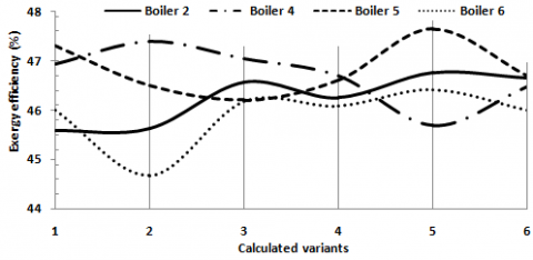
The exergytic performance in the generation system has an equally stable behavior, with oscillations between 44.67 and 47.65% (see Figure 7). It is evident that boilers 2, 4 and 5 are more efficient than boiler 6, because the average efficiency of the former is 0.7% bigger than the latter. In general, in the SGV the use degree of the available exergy is low, its value amounts to 46.417%, which may be attributable to the irreversibility of the combustion processes and the formation of water in steam, due to the notable difference of temperature that exists between the working substance and the gases produced by combustion [18, 19].
Figure 6. Gross thermal efficiency
The GV-6, despite being more modern than the rest, has lower thermal and exergy efficiency. This could be associated to the change of fuel with respect to that foreseen in its design (without the proper modification of the burners) and to the problems that it has presented in the combustion chamber and the oven (fouling of the heat transfer surfaces, corrosion and melting water pipes, among others), which have limited the use of heat in the home and other surfaces of heat exchange.
Figure 7. Exergetic efficiency
As inferred, the energy behaviors of the investigated steam boilers have direct impacts on the net thermal performance; the economic indicators of the company and on the environment, these aspects will be analyzed in subsequent works.
An algorithm was developed to apply the predetermined methodology for the thermo-energy balance of the studied steam boilers. The applied method synthesizes the nested procedures in preceding works, establishes the methodology to follow and defines the required parameters for the thermal evaluation by means of the application of the direct and indirect methods, besides, the exergetic evaluation of the studied steam generators.
An analysis of the thermo-energy performance of steam boilers was carried out, confirming that these facilities have a high rate of use of thermal energy. However, the capacity of utilization of the available exergy is low, due to the deterioration of some operation parameters and to the irreversibilities associated to the combustion processes, heat transfer and transformation of water in vapor. The thermal and exergetic performances were increased to 90.14 and 46.42% respectively, while, the degree of exergy loss was a 53.58%.
It was evidenced than in the steam boilers have deteriorated, in relation to the designing values, several operational parameters, (production, temperature and pressure of the superheated steam), besides, the quality of the fuel and the temperature of water supply and exhaust gases, also have changes. The causes that originate these modifications can be mitigated by means of the implementation of scientific actions and technician organizational, that contribute to increment thermal and exergetic efficiency of the steam boilers. This aspect, once integrated to the optimization energetic-operational of the boilers, will be investigated subsequently.
[1] Buecker, B. (2012). Basics of Boiler and Heat Recovery Steam Generator Design. PennWell Corporation. Oklahoma.
[2] Martha de Souza, G.F. (2012). Thermal Power Plant Performance Analysis. Springer, London.http://doi.org/10.1007/978-1-4471-2309-5
[3] Nag, P.K. (2008). Power Plant Engineering. Tata McGraw-Hill, New Delhi.
[4] Borroto, A., Rubio, Á. (2010). Combustión y Generación de vapor. Editorial Félix Varela. La Habana.
[5] Herrera, I., De Ruyck, J., Ocaña, V.S., Rubio, M., Martínez, R.M., Núñez, V. (2013). Environmental impact of decentralized power generation in Santa Clara City, Cuba: An integrated assessment based on technological and human health risk indicators. Applied Energy, 109: 24–35. http://doi.org/10.1016/j.apenergy.2013.03.085
[6] Flynn, D. (2013). Thermal Power Plant Simulation and Control. Springer. London.
[7] Beatón, P., Silva, E., Oliva, L. (1988). Explotación y materiales constructivos de generadores de vapor. Ediciones ISPJAM. Santiago de Cuba.
[8] Borroto, A., Rubio, Á. (2007). Combustión y Generación de vapor. Editorial Universo Sur. Universidad de Cienfuegos.
[9] Çengel, Y., Boles, M. (2019). Thermodynamics: An Engineering Approach, 9ed, McGraw-Hill.
[10] Clavelo, P. (2003). Simulación del sistema de generación de vapor y procesos de depuración de SO2 y NOX. Ingeniería Mecánica, 3(6): 53-60.
[11] Patro, B. (2015). Efficiency y studies of combination on tube boilers. Alexandria Engineering Journal, 55(1): 193-202.http://doi.org/10.1016/j.aej.2015.12.007
[12] Tirumala, G., Rajeev, D., Vithal, P., Nageswara, B. (2017). Efficiency of a coal fired boiler in a typical thermal power plant. American Journal of Mechanical and Industrial Engineering, 2(1): 32-36. http://doi.org/10.11648/j.ajmie.20170201.15
[13] Camaraza-Medina, Y., Cruz-Fonticiella, O.M., García-Morales, O.F. (2018). Predicción de la presión de salida de una turbina acoplada a un condensador de vapor refrigerado por aire. Centro Azúcar, 45(1): 50-61.
[14] Harish, S., Baldi, S. (2018). Monitoring energy efficiency of condensing boilers via hybrid first principle modelling and estimation. Energy, 142: 121-129. https://doi.org/10.1016/j.energy.2017.09.124
[15] Liu, X.Z., Li, R.Y., He, C.H., Li, Y.S., Wu., H.W. (2018). A simplified mathematical model for calculating the thermal efficiency of a wood pellets-fired industrial boiler on the basis of error analysis method. Science Journal of Energy Engineering, 6(2): 37-41. https://doi.org/10.11648/j.sjee.20180602.12
[16] Jiménez, J., Jarquin, G., Durán, M., García, J. (2011). Análisis exergético del generador de vapor de 350 MW a cargas parciales. MACI, 3: 715-718.https://doi.org/10.13140/RG.2.1.2268.6805
[17] Krasniqi-Alidema, D., Filkoski, R., Krasniqi, M. (2018). Exergy efficiency analysis of Lignite-Fired Steam generator. Thermal Science, 22(5): 2087-2101.https://doi.org/10.2298/TSCI180131265.
[18] Fernández-Conde, E. (1994). Termodinámica Técnica. Editorial Félix Varela, La Habana.
[19] Velázquez, A., Corrales, J., Pérez, L. (2019). Evaluación termoexergética del generador de vapor del campus Lenin de la Universidad de Las Tunas. Opuntia Brava, 12(1): 454-468.
[20] Lincheta, E., Súarez, J., Barroso, J. (2000). Estudio de modificaciones geométricas en boquillas de calderas piro y acuotubulares para la combustión eficiente de crudos pesados. Ingeniería Mecánica, 3(3): 7-18.
[21] Rodríguez‐Ramos, A., Llanes‐Santiago, O. (2014). Diagnóstico de fallos en un generador de vapor BKZ‐340‐140‐29M utilizando herramientas de lógica difusa. Ingeniería Mecánica, 17(2): 147-156.
[22] Anjani-Devi, S., Kamesh, V. (2017). Analysis of a boiler shell at various conditions using FEA. International Journal of Research and Innovation, 4(1): 659-669.
[23] Valencia, G., Piero, J., Campos, J.C. (2019). Energy optimization of industrial steam boiler using energy performance indicator. International Journal of Energy Economics and Policy, 9(6): 109-117.https://doi.org/10.32479/ijeep.8188
[24] Seshendra, V. (2012). A theoretical investigation of efficiency enhancement in thermal power plants. Modern Mechanical Engineering (MME), 2(3): 106-113.http://dx.doi.org/10.4236/mme.2012.23013
[25] Camaraza-Medina, Y., Hernández-Guerrero, A, Luviano-Ortiz, J.L, Mortensen-Carlson, K, Cruz-Fonticiela O.M., García-Morales, O.F. (2019). New model for heat transfer calculation during film condensation inside pipes. International Journal of Heat and Mass Transfer, 128: 344-353.https://doi.org/10.1016/j.ijheatmasstransfer.2018.09.012
[26] Jiménez, R., Madrigal, J., Lapido, M., Vidal, D. (2016). Método para la evaluación de la eficiencia e impacto ambiental de un generador de vapor. Ingeniería Energética, 37(2): 135-144.
[27] Camaraza-Medina, Y., Hernandez-Guerrero, A., Luviano-Ortiz, J.L., Cruz-Fonticiella, O.M., García-Morales, O.F. (2019). Mathematical deduction of a new model for calculation of heat transfer by condensation inside pipes. International Journal of Heat and Mass Transfer, 141: 180-190.https://doi.org/10.1016/j.ijheatmasstransfer.2019.06.076
[28] Clavelo, P. (2004). Estrategia para el desarrollo de habilidades de análisis y solución de problemas energético-ambientales (Ph.D. Thesis), CUJAE, La Habana, Cuba.
[29] Ganapathy, V. (2013). Industrial Boilers and Heat Recovery Steam Generators: Design, Applications and Calculations. Marcel Dekker, Inc. New York.
[30] Rubio, A. (2015). Generadores de vapor. Funcionamiento y explotación. Editorial FeijóoSanta Clara.
[31] Peduzzi, E., Boissonnet, G., Maréchal, F. (2016). Biomass modelling: Estimating thermodynamic properties from the elemental composition. Fuel, 181, 207-217. http://dx.doi.org/10.1016/j.fuel.2016.04.111
[32] Cabrera, R., Vizcón, R. (2007). Evaluación termo económica de un generador de vapor pirotubular. Revista Avanzada Científica, 10(3): 1-12.https://doi.org/10.13140/2.1.2427.9049
[33] Valles, A., Acosta, L., Pérez, A. (2014). Evaluación energética de los generadores de vapor F1-2 y BH-109 de una refinería cubana de petróleo. Revista Especializada en Ingeniería, 8:90-96.https://doi.org/10.22490/25394088.1291
[34] Borroto, A. (2005). Ahorro de energía en sistemas de vapor. Editorial Universidad de Cienfuegos, 31: 86-92.
[35] Kitto, J.B., Stultz, S.C. (2015). Steam, its generation and use. The Babcock & Wilcox Company, Ohio.
[36] Keenan, J.H. (2013). ASME Steam Properties for Industrial Use, Based on IAPWS-IF97. ASME, New York.
[37] Fonseca, A. (2009). Análisis termoexergético de los generadores de vapor de la empresa Ernesto Che Guevara. (Mechanical Engineering Thesis), Instituto Superior Minero Metalúrgico de Moa, Cuba.
[38] Camaraza, Y. (2017). Introducción a la termotransferencia, Editorial Universitaria, La Habana.
[39] Hernández, N. (2006). Diagnóstico térmico verificativo de los generadores de vapor 6 y 7 insertados en el proyecto de modernización de la Central Termoeléctrica. (Mechanical Engineering Thesis), Instituto Superior Minero Metalúrgico de Moa, Cuba.