Houcine Salem*![]() | Hamid Abouchadi
| Hamid Abouchadi![]() | Khalid El Bikri
| Khalid El Bikri![]()
© 2025 The authors. This article is published by IIETA and is licensed under the CC BY 4.0 license (http://creativecommons.org/licenses/by/4.0/).
OPEN ACCESS
Additive manufacturing (AM), also known as 3D printing, is a process of creating physical objects directly from digital 3D models by adding material layer by layer. Unlike conventional manufacturing methods—such as subtractive machining or injection molding—which remove material or shape it within molds, AM builds parts incrementally, typically using heat, lasers, or electron beams to bond each layer. Among the seven standardized AM processes, Fused Deposition Modeling (FDM) is the most widely used. FDM works by heating and extruding thermoplastic filaments to form successive layers of a part. While AM offers unique advantages such as complex geometries, lightweight structures, and customization, it also introduces specific design constraints that differ from traditional manufacturing. This paper reviews key design challenges associated with AM, with a focus on FDM, and evaluates current methodologies developed to address these issues. A new design methodology is proposed to optimize part design according to specific machine and material constraints, leveraging the advantages of AM while minimizing its limitations. This approach ensures that designs are not only manufacturable but also meet performance requirements and are optimized for the given specifications. A case study applying this methodology to the FDM process highlights its effectiveness and suggests pathways for further improvements. The findings offer insights into how the new approach can contribute to future research and development in AM design optimization.
3D printing, additive manufacturing, design methodology, Fused Deposition Modeling
The physical principle of AM is very old, appearing at the end of the 19th century and developed in the context of two distinct applications considered today to be the ancestors of AM: photosculpture and topography [1, 2]. AM has been evolving since the late 1980s, when it first entered the industrial era, and its selection of machines and processes has grown significantly. This expansion of the range has been facilitated in particular by the increased processing capabilities of computers. Indeed, it was thanks to their increased computing power that Computer Aided Design (CAD) was developed, enabling the 3D representation of digital objects and arousing the desire to manufacture them [3]. Many fields use AM processes to improve their products [4].
During its first years of industrial existence between 1990 and 2000, AM was limited almost exclusively to Rapid Prototyping (RP). Previously considered a complex, tedious and costly step [5], which slowed down the design process, RP has become much simpler and faster with AM. Today, the diversity is such that ASTM and ISO have proposed a classification of AM into 7 process categories, which brings some clarification to the many “commercial variations of technologies” [6]:
Additive manufacturing (AM) is recognized as a transformative innovation in production technology, having initiated a significant shift in manufacturing processes in recent years. Unlike conventional methods such as material removal (e.g., machining) or forming techniques (e.g., casting and forging), AM operates through a generative process. This paradigm shift has led to the emergence of new design for additive manufacturing (DFAM) methodologies, aimed at optimizing part design to leverage the unique advantages of AM while mitigating its limitations.
Design for additive manufacturing (DFAM) refers to the set of principles, strategies, and tools specifically developed to optimize product designs for additive manufacturing processes. Unlike traditional design approaches that are constrained by the limitations of conventional manufacturing methods, DFAM leverages the unique capabilities of AM—such as geometric complexity, part consolidation, and material efficiency—to create more innovative and functional components.
The main objectives of DFAM include:
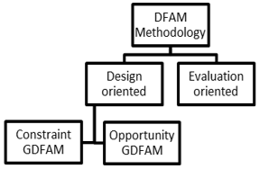
There are three types of design methodologies for additive manufacturing (DFAM), illustrated in Figure 1. The first is evaluation DFAM [14], such as process selection methodology. In this case, the aim is to determine the right process for manufacturing a part. This method is based on cost, the mechanical response of the material being manufactured, and the performance and usable volume of the machines.
Figure 1. Types of design methodologies for AM
The second type of design methodology uses two approaches, the “opportunity” approach and the “constraint” approach [15]. There are no restrictions on the shape or complexity of the part, the only constraints being those imposed by the specifications and manufacturing processes. Each volume is functional, mandatory and minimum. Product topology is optimized according to the process used. The aim of this type of method is to reduce weight, manufacturing time and thus production cost, depending on the approach used.
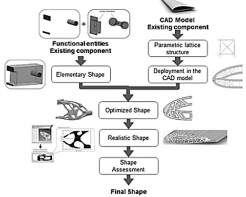
The third type of design methodology is global DFAM (GDFAM) [16]. This type of method integrates the “opportunity” approach in parallel with the “constraint” approach. GDFAM solutions are tailored to the specific requirements, and are manufacturable and optimized for the chosen process and machine. There are two types of GDFAM, depending on the project: the first corresponds to component optimization (GDFAM-C) and the second to assembly optimization (GDFAM-A), illustrated in Figure 2.
Figure 2. Workflow of the DFAM-C [18]
Within each DFAM category, two main approaches—direct and indirect—can be distinguished based on their objectives and implementation strategies. The direct approach focuses on adapting the design to meet the specific challenges and constraints of the additive manufacturing process. This method is typically applied to the re-engineering of existing parts or prototypes, where the geometry is already defined and the goal is to ensure manufacturability, reduce defects, or improve print reliability.
In contrast, the indirect approach emphasizes adapting or optimizing the manufacturing process itself to achieve broader efficiency gains. Rather than working from a fixed design, this approach often starts from a clean slate and aims to reduce production costs, lead times, and material usage by taking full advantage of AM capabilities. Indirect methods are particularly useful during the early stages of product development, where design freedom is high and there is greater potential for innovation through process-aware design strategies.
In 2014, Ponche [17] introduced a GDFAM-C methodology tailored for new product design using the direct metal laser sintering (DMLS) process. This design approach integrates functional specifications and machine parameters as input data, guiding the designer through a series of steps to select solutions that align with these constraints. Ponche’s methodology [17] addresses the challenge of balancing functional requirements with machine characteristics, following the theoretical principles of an effective design process. It employs an “opportunity” approach that harnesses AM’s potential for innovative solutions, alongside a “constraint” approach that adapts designs to specific processes and machines. As a result, the proposed solutions are manufacturable, optimized, and meet specification requirements. However, certain limitations remain, such as the fixed nature of topological optimization outputs, which often result in irregular shapes. The methodology would benefit from an additional step to smooth surfaces, particularly external ones, and to account for the impact of manufacturing orientation on mechanical performance.
Boyard et al. [15] developed a GDFAM-A methodology specifically for assemblies, structured around three distinct phases and a function graph that manages components based on their roles within the assembly. The first phase identifies functional surfaces that satisfy specification requirements. The second phase generates geometry with optimized topology, while the final phase ensures manufacturability. Unlike earlier methodologies, this approach acts as a software-based design assistant, guiding designers toward innovative, optimized solutions that adhere to specifications. By utilizing the function graph, each functional surface can be modified independently, followed by defining a minimum volume and connecting the different shapes to form a part that meets the design criteria. The structured progression through these steps, along with consideration of manufacturing processes and equipment, serves as the foundation for Boyard's methodology.
Existing methodologies often rely on multiple software tools, posing the risk of disrupting the design workflow. Typically, modeling software is followed by simulation and topological optimization tools, and then AM-specific software for manufacturing preparation.
Topological optimization is a powerful design strategy in DFAM that removes unnecessary material from a part to improve performance metrics such as strength-to-weight ratio or stiffness. However, this process often results in highly irregular, organic geometries that, while optimal in theory, pose several challenges in practice.
One major challenge is manufacturability. The complex and non-uniform surfaces generated through topological optimization can be difficult to print without extensive support structures, particularly in processes like Fused Deposition Modeling (FDM) or Selective Laser Melting (SLM). These supports not only increase material usage and post-processing time but may also affect surface quality.
Another concern is mechanical performance under real-world conditions. Irregular shapes may introduce stress concentrations at sharp corners or thin connecting regions, which can become initiation points for cracks or fatigue failure. Furthermore, anisotropy inherent in many AM processes where mechanical properties vary by build orientation can compound the problem if not carefully accounted for during optimization.
To address these issues, it is essential to integrate simulation-driven validation into the design loop, ensuring that optimized geometries not only meet theoretical goals but also perform reliably under actual loading conditions. Additionally, hybrid design strategies that balance topological optimization with geometric simplification may help improve both manufacturability and structural robustness.
To address the current fragmentation in additive manufacturing workflows, this study proposes a novel, unified methodology–Global Design for Additive Manufacturing for Components (GDFAM-C)–that consolidates all design stages within a single software platform. Unlike existing approaches, which often rely on disconnected tools and overlook critical process-specific factors, GDFAM-C integrates essential design functions to streamline the workflow and enhance part performance.
The novelty of this study lies in its comprehensive approach to optimizing component design for Fused Deposition Modeling (FDM). Specifically, the methodology introduces three key innovations:
By aligning design practices with the specific constraints and capabilities of FDM systems, the GDFAM-C methodology not only ensures conformance to functional specifications but also enhances production efficiency and structural integrity. The effectiveness of this approach is demonstrated through a detailed case study, which validates the methodology’s impact on both design quality and mechanical performance.
Following the introduction, Section 2 presents the materials and methods used in this study. It begins with an overview of the Fused Deposition Modeling (FDM) process, highlighting both its capabilities and limitations. This is followed by a detailed description of the proposed GDFAM-C methodology, which is structured into six key stages: defining the functional and design domains, conducting a static study, performing topology optimization, refining the process domain, and running simulations to validate the design.
Section 3 discusses the results, including the application of the methodology to a case study, where its effectiveness is evaluated against functional and mechanical performance specifications. Finally, Section 4 summarizes the main findings and outlines potential directions for future research.
This section begins by outlining the FDM process, which the proposed methodology addresses, emphasizing the limitations that must be considered to optimize design. Following this, the methodology is introduced, with a focus on its key advantages. Each step of the methodology is then thoroughly explained in detail.
2.1 Fused Deposition Modeling
2.1.1 Process presentation
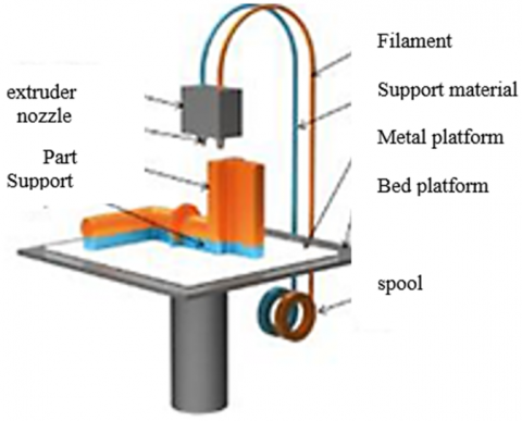
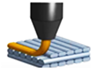
Scott Crump pioneered Fused Deposition Modeling (FDM) in the late 1980s [7], a form of additive manufacturing that constructs 3D components using filament, illustrated in Figure 3. In this process, an extruder melts the filament and deposits it layer by layer onto specific areas of a build tray along a predefined path.
Figure 3. FDM principle [19]
Compared to other additive manufacturing technologies, FDM has lower dimensional accuracy and resolution, with parts often exhibiting visible layer lines, making post-processing necessary for achieving smooth, sharp surfaces. Additionally, due to its layer adhesion process, FDM parts are inherently anisotropic. Despite these limitations, FDM remains the most cost-effective method for producing custom components and prototypes. Its affordability and widespread availability, combined with a variety of available materials—including polymers, metal alloys, ceramics, composites, mortar, and recycled materials—make FDM one of the most accessible AM technologies.
Table 1. Process limitations
|
Limitation |
Description |
|
Hole orientation |
In the case of components with multiple holes in different directions first prioritize blind holes, then holes from smallest to largest diameter, then Diameter, then the criticality of the hole size. Drilling after printing is recommended if high precision is required. |
|
Bridges |
If a bridge exceeds a certain value, sagging or marking of the supporting material may occur. Design splitting or post-treatment is therefore required to eliminate this problem. |
|
Overhangs |
For overhangs, the maximum angle that guarantees manufacture is generally 45 degrees, but this may vary slightly depending on the material and the machine used. The addition of support will enable FDM printers to print angles greater than 45 degrees. |
|
Elephant foot |
A chamfer or 45-degree radius is required on all edges of a part touching the worktable. The aim is, among other things, to prevent the part from becoming detached or warped. |
|
Diameter variation |
A difference is often noted between the theoretical and practical diameters of the circular layers deposited. This is due to the compression of the extruded profiles. This must be taken into account when calculating the precise dimensions of manufactured parts. |
|
Effect of layer orientation on mechanical properties |
The mechanical characteristics of the parts depend on the orientation of the filaments during manufacture. The ideal manufacturing direction to withstand external stresses must therefore be taken into account. |
|
Stress concentrations |
Mechanical properties are also influenced by stress concentrations in the interlayer on the outer surface. This must be taken into account when simulating the mechanical performance of products. |
|
Shells |
To improve part strength, it makes sense to increase the thickness or number of shells. However, any increase in the number of shells also increases the time and material required to print the model. |
|
Infill |
The filling percentage is decided by the designer and is a compromise between cost, weight and time on the one hand, and mechanical characteristics on the other. |
3D printers can be equipped with either a single nozzle or dual extrusion nozzles. In dual nozzle configurations, one nozzle is designated for the model material and the other for support material; alternatively, both nozzles may be used with different colored filaments. The extruders can operate with the same material or with distinct materials. The movement along the XYZ axes may involve both extruders and the build platform, depending on the machine's architecture. The most prevalent design is the Cartesian architecture, where the build platform moves in the X and Y directions while the extruder operates in the Z direction. Other architectural types include polar, Delta, SCARA, and belt configurations. All FDM machines utilize the same energy source (heat) to melt the filament, with the temperature calibrated according to the specific material being processed.
2.1.2 Process limitations
Table 1 represents some limitations that must be taken into account in the methodology to obtain an optimized part for 3D printing.
In summary, the design guidelines that must be adhered to in order to ensure the manufacturability of FDM parts should align with the specifications and constraints of the respective machine. The intended function of the part must be understood before determining shell thickness and filling percentage, as increasing these parameters enhances strength but also prolongs printing time. Additionally, shell thickness should be a multiple of the nozzle diameter to optimize performance. When adjusting shell thickness or filling percentage, it is essential to improve anchoring. If this is unfeasible, the use of clearance holes and bolts, accompanied by washers to maintain surface quality, should be considered. For efficient and cost-effective printing, a rectangular infill pattern is preferable due to its rapid printing speed. However, if strength is paramount for the part's function, honeycomb or triangular infill patterns are recommended, as they provide superior strength compared to rectangular infill.
In conclusion, a design methodology tailored to the specific process, specifications, and machine is essential for leveraging the advantages of FDM while minimizing its limitations.
2.2 Proposed DFAM methodology
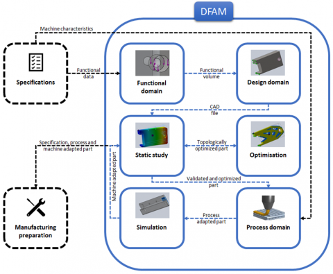
This section outlines the methodology developed by the author, illustrated in Figure 4, described in Table 2. The proposed GDFAM-C methodology builds upon the strengths of previously discussed methodologies while introducing several enhancements. It begins by highlighting the added value of the method in terms of the software tools employed, design assistance, optimization, and manufacturing processes. The section concludes with a comprehensive presentation of the author's methodology, providing a detailed, step-by-step explanation of each modeling stage.
The proposed methodology is grounded in a thorough analysis of the existing literature, resulting in six key advantages:
To implement the methodology, SolidWorks software has been employed for all design and simulation stages to prevent any disruptions in the workflow during soft-ware transitions. However, alternative software packages may be utilized as long as they adhere to the prescribed steps of the methodology. The subsequent sections will provide a detailed explanation of each step in the methodology independently.
2.2.1 Functional domain
The initial step in the methodology involves translating the specifications into technical data suitable for the design process, enabling the creation and optimization of the 3D model of the component according to predefined objectives. The data to be extracted from the specifications includes the following elements, described in Table 3:
Figure 4. Proposed GDFAM-C methodology
Table 2. DFAM methodology description
|
Step |
Illustration |
Description |
|
Functional domain |
The initial step in the methodology involves analyzing the specifications to extract essential data required for defining the functional domain (Part type, Dimensions, Optimization goal, Mechanical properties, Limit conditions, Physical properties, Assembly constraints. |
|
|
Design domain |
The preliminary design domain corresponds to the initial volume that satisfies the specifications, encompassing both dimensional and geometric requirements. This volume is determined through functional dimensioning, which examines various technical functions such as guidance, connection, lubrication, sealing, resistance, and assembly of the component within its operational context. |
|
|
Static study |
If a specific material is specified, a static analysis is conducted to evaluate the mechanical behavior of the initial part. In cases where no material is indicated, the analysis identifies the most suitable material for the component. |
|
|
Optimization |
Optimization efforts may focus on factors such as mass, volume, force, deformation, stress, or a combination of these objectives. Since the output may not always yield a visually representative design, the result is refined to achieve an aesthetically pleasing appearance while adhering to the established objectives. This final iteration undergoes an additional static analysis. |
|
|
Process domain |
After validating the studies against the specifications, the next step is to assess the compatibility of the FDM process with the part, in terms of process, material and transformation source compatibility, machine characteristics, cost and functional requirements. |
|
|
Simulation |
This is followed by manufacturing simulation to establish an appropriate manufacturing strategy. At the conclusion of this stage, the resulting part aligns with the objectives and specifications, confirming its readiness for production using the selected process, thereby completing the design process. |
Table 3. Specifications extracted data
|
Extracted Data |
Explanation |
|
Part type |
New design or reverse engineering |
|
Optimization objective |
The optimization objectives must be determined. These include:
|
|
Dimensions |
This step also involves drawing up the geometric and dimensional specifications of the functional domain, which define the functional surfaces including the areas where forces or displacements are applied. These data will be used in the methodology to determine the functional volume that meets the specification criteria. These are:
|
|
Constraints |
Next, the external loads and constraints that must be taken into account when optimizing the part, such as:
|
|
Boundary conditions |
Boundary conditions must also be extracted for use in static calculations, optimization and design simulation. These conditions will be integrated into the design optimization and simulation as far as displacements are imposed. |
|
Assembly constraints |
This step consists in determining the assembly constraints of the part within an assembly. |
|
Materials data |
The next step is to extract the material properties (mechanical, physical, chemical, thermal, electrical, magnetic, acoustic, optical, etc.) that are related to the part's function and that can be optimized. |
|
Comparison criteria |
The next step is to choose the criteria for comparing the parts resulting from the methodology. The general comparison parameters for 3D printing are presented below, however, depending on the specifications and the manufacturing process, other selection criteria may be added or removed:
|
|
AM added value |
Once the specifications have been analyzed, we need to decide whether it is worthwhile to use AM to manufacture the part. The use of AM processes must add value and validate one or more of the following criteria:
That said, any type of optimized part can benefit from being manufactured using AM. Indeed, the results of topological optimization are often complex shapes that are difficult to manufacture using conventional processes. |
The functional domain encompasses the functional surfaces that correspond to all contact surfaces identified through the analysis of the specifications. This domain includes regions subjected to forces and displacements, as well as areas necessary for assembly with other components. Additionally, it incorporates dimensional specifications and geometric tolerances.
The output at this stage consists of the various functional surfaces along with their respective dimensions and tolerances.
2.2.2 Design domain
Building on the data from the previous section, this part involves utilizing that information to establish a volume that encompasses all functional specifications of the product. This volume must include the functional entities corresponding to areas where forces and displacements are applied and should be based on the dimensions and tolerances specified earlier. Additionally, it must account for freedom of movement and the areas required for assembly with other system components.
To translate the specifications into functional conditions, the methodology outlines a series of iterative steps aimed at deriving the functional volume, described in Table 4.
Table 4. Iterations for the design domain
|
Step |
Illustration |
Description |
|
Functional volume |
Define a volume containing all the part's functional surfaces. |
|
|
Dimensions |
Integration of dimensional and geometric specifications from the design brief. |
|
|
Assembly |
Integration of assembly constraints (type of connection: mobile or fixed, which determines fit (tight or fixed, etc.), lubrication and sealing, guidance: positioning and holding in position, fit) with other components. |
|
|
Thickness |
Transforms functional surfaces into functional volumes with a thickness that satisfies the specifications. |
|
|
Material |
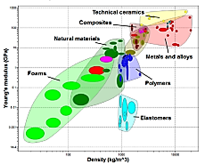
In the case of materials not defined by the specifications, the choice of material is made at this level according to the volume obtained and the constraints of the specifications. The "Ces EduPack" software can be used in this case. This is a tool for making comparative material choices based on functional specifications and manufacturing constraints. For the methodology, the material must be compatible with the FDM process [20]. |
The output at the conclusion of this stage is a CAD file representing a volume that incorporates the functional surfaces while adhering to the specified dimensions, tolerances, and requirements.
2.2.3 Static study
Static studies are conducted to verify the behavior, geometry, and material of the part in alignment with the specifications, illustrated in Figure 5. In cases of non-compliance, the methodology allows for modifications to the geometry and material by reverting to the preceding step. These studies are performed three times within the methodology: once after defining the initial design volume, again following the optimization phase, and finally after the integration of process parameters and simulation of manufacturing.
Figure 5. Illustration of static study results (stress–displacement–strain)
In this stage, the obtained model is meshed with a set of fixtures and loads. The linear static analysis program initiates by constructing and solving the system of linear equilibrium finite element equations to determine the displacements at each node. Subsequently, these displacements are utilized to calculate the deformation components. Following this, the program applies the resulting strains and the stress-strain relationship to determine the stresses. While the equivalent stress at a specific point does not uniquely define the stress state at that location, it provides valuable information for assessing the safety of the design concerning various ductile materials. Unlike stress components, equivalent stress is directionless and is entirely characterized by its magnitude, measured in units of stress.
To evaluate the safety factor at different points, a SolidWorks tool (SimulationXpress) employs the von Mises criterion, which asserts that a ductile material begins to yield when the equivalent stress reaches its yield point. The output at the conclusion of this stage is an assessment of the mechanical behavior of the analyzed part.
2.2.4 Optimization
This stage of the methodology is based on the previously defined volume, in order to optimize it topologically to meet specifications. The methodology is based on the SIMP (Isotropic Material with Penalization Method). This mathematical method, proposed by Bendsøe [21] and Salem et al. [22], is the most popular for topological optimization. According to Aoussat [23]: “Shape optimization, in its most general framework, should consist of determining for each point in space whether or not there is matter at that point”. The method thus makes it possible to define the optimum distribution of material in a given space, in compliance with given loads, boundary conditions, manufacturing constraints and performance, as well as the different types of optimization.
Typically, the optimization objective focuses on maximizing the structure's stiffness while minimizing compliance and reducing a specified amount of material. During each iteration, the optimization algorithm conducts a sensitivity analysis to evaluate the effects of varying material density on the objective of stiffness maximization.
The methodology is grounded in the maximum design domain that complies with the criteria set forth by the specifications and the manufacturing machine used. Through successive iterations, this process yields a lighter design that continues to satisfy the specifications and design objectives. This is facilitated by the software's topology study tool. While the methodology relies on a straightforward topological study, the software also offers advanced options for modifying the solver, defining retained regions, and setting the maximum number of iterations. Regarding manufacturing control, the methodology suggests generating multiple solutions based on different manufacturing orientations. The resulting shapes will undergo objective comparison at the conclusion of the methodology, adhering to the evaluation criteria established in the initial step.
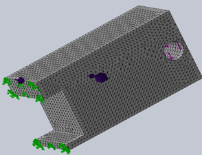
All the data required for the topological study comes from the design and process domains, except for the mesh. The first step is then to determine the appropriate mesh size. The ideal mesh, to guarantee a manufacturable result, should be two to three times smaller than the minimum machine thickness [24]. The methodology recommends the use of smoothed mesh, which creates a softer mesh, illustrated in Figure 6. This eliminates sharp corners and irregular edges, while preserving part conformity. For AM, it is advisable to opt for mesh smoothing with the smoothest possible transition.
Figure 6. Meshing illustration
Once all necessary information for the topological study has been input, the analysis can commence. Elements with a relatively low mass density (less than 0.3) are classified as soft elements, which do not contribute to the rigidity of the part and can thus be eliminated. Conversely, elements with a higher mass density (greater than 0.7) are categorized as solid elements, as they enhance the rigidity of the component and are retained in the final design. The topological optimization is conducted using a single objective function, after which the designer can initiate additional studies for different objectives. The methodology recommends initially focusing on enhancing the weight-to-stiffness ratio, regardless of the objective functions outlined in the specifications.
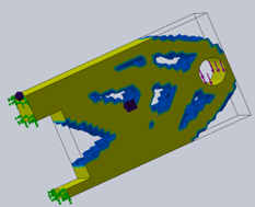
The study produces several visual representations, the first of which depicts the mass of the material in Figure 7. The program includes a value slider that enables the addition or removal of material and modification of the density threshold while adhering to the predefined constraints. The material mass is plotted based on the slider's position, with the software displaying the percentage of mass removed and the resultant weight obtained.
Figure 7. Illustration of the adaptation of part mass
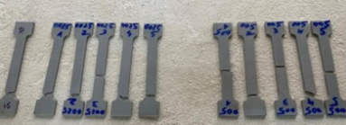
The designer is presented with multiple options for altering the volumetric body, allowing for the addition of material or the reduction of structure weight based on the constraints of the specifications and the desired visual appearance of the final result. The designer can save various iterations and proceed with the methodology. After simulating the mechanical behavior and estimating the material quantity and percentage of support needed, the outcomes will be assessed objectively. The resulting visualizations illustrate Von Mises stresses, resulting displacements, and variable body deformations. These values are derived from a model assumed to be fully dense. However, for FDM processes, a 100% infill does not necessarily ensure full density of the part [25]. To highlight this distinction, the author conducted tests on standardized specimens to compare the theoretical material results with the practical outcomes of parts produced using FDM. The conclusion indicates that the values should be viewed as approximate estimates of the final model's performance, and a safety factor should be incorporated to ensure the mechanical integrity of the part.
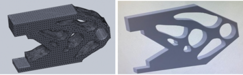
The shapes produced exhibit significant surface roughness. The methodology recommends modifying the resulting part to improve the design by softening the edges and achieving a smoother surface finish in Figure 8.
Figure 8. Step to improve the visual appearance
The output at the conclusion of this stage is a topologically optimized component featuring enhanced surface qualities.
2.2.5 Process domain
The methodology adopts an indirect approach, emphasizing the integration of process characteristics at the earliest possible stage to ensure manufacturability and assist the designer in determining optimized volumes based on the selected process and machine. Each manufacturing process has its specific applications, along with distinct advantages and disadvantages. Therefore, it is essential to consider several manufacturing-related factors, including:
When multiple processes fulfill the manufacturing constraints of the part, the final selection is determined by the availability of the technology and associated costs. If no process meets the manufacturing requirements, the methodology advises reverting to the previous step to modify the functional volume, integrating the constraints of the selected process.
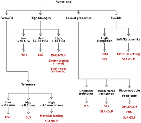
The proposed methodology is specifically tailored for the Fused Deposition Modeling (FDM) process, with compatible parts requiring low form tolerances (±0.5 mm), low stress levels (<30 MPa), and compatible material properties [7], illustrated in Figure 9. The goal of this step is to establish an appropriate environment that ensures and optimizes the manufacturing of the component. To achieve this, the derived volume must be considered alongside the parameters of the process and the selected machine.
Figure 9. Process selection based on functional requirements [7]
The steps involved in defining the design process are as follows:
The process of defining the manufacturing domain begins by identifying regions that must remain unchanged to ensure the part's functionality, particularly those in contact with other components, such as bearing and functional surfaces. These areas will not be influenced by the optimization of the initial volume, and the selected surfaces will be assigned a thickness greater than what is permissible by the machine in Figure 10.
Figure 10. Preserved regions integration
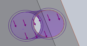
Thickness control involves imposing dimensional constraints on both the minimum and maximum allowable thicknesses based on the manufacturing process. The primary objective is to ensure the manufacturability of the geometries produced through optimization. Depending on the specific machine employed, the minimum and maximum section thicknesses must be specified. However, entering these thickness limits can significantly increase calculation times. To mitigate this, it is advisable to define thickness constraints only for critical areas of the model.
Subsequently, the manufacturability check assesses the ability to produce the part using the selected process, helping to prevent the creation of hollow shapes or geometries that are challenging to manufacture. At this stage of the methodology, the part's resistance to external stresses has been confirmed. Nevertheless, it is essential to select the most suitable manufacturing orientation. The orientation during fabrication is a crucial factor in ensuring the mechanical strength of the component, particularly for the Fused Deposition Modeling (FDM) process, due to the anisotropic behavior of the material [7]. Specifically, components exhibit significantly greater strength in the XY plane compared to the Z plane. Therefore, the manufacturing direction must be aligned with the anticipated external loads.
The manufacturing direction must also consider the amount of support material required, as this leads to material wastage and increased manufacturing time, alongside additional post-processing challenges that can compromise surface quality. Nonetheless, it is important to note that a layer of material cannot be deposited in mid-air; therefore, the incorporation of support structures is sometimes crucial for the production of complex parts.
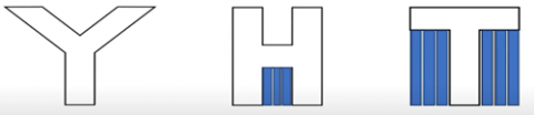
The methodology utilizes the YHT rule, illustrated in Figure 11, to determine the necessity of support structures for a given part. In this rule, the "Y" represents angles that are less than or equal to the overhang angle that the machine can achieve, ensuring that successive layers have sufficient material to support themselves without requiring additional supports. This approach results in improved surface finish, reduced material usage, and optimized manufacturing time. It is worth noting that the overhang angle may vary across different processes. For the "H" and "T" configurations, the angles exceed the permissible overhang angle, thus necessitating the addition of supports to ensure the stability of the stacked layers in Figure 11.
Figure 11. Support management illustrated with the letters YHT [19]
For the YHT rule, predicting overhang surfaces that necessitate support is relatively straightforward. However, in the case of more intricate designs, it becomes challenging to determine whether certain volumes surpass the overhang angle threshold that mandates support. To address this, the methodology recommends utilizing a SolidWorks tool known as the undercut analysis tool, which assists in identifying regions that may require support structures. By selecting the face intended to contact the manufacturing platform and specifying the overhang angle limit, the software promptly highlights the areas that will necessitate support.
The result at this stage is a topologically optimized part that is tailored to the FDM process and aligned with the machine's characteristics.
2.2.6 Simulation
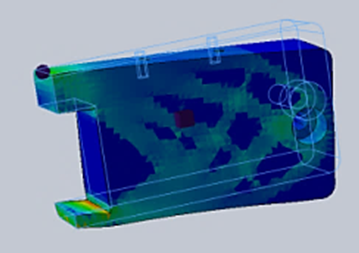
The goal at this stage is to simulate the process domain in order to assess the manufacturability of the design in Figure 12. The initial step involves identifying regions of the part that may pose manufacturing challenges. After inputting machine characteristics such as thickness limits, overhang angles, and manufacturability orientations, the software highlights specific areas that render manufacturing unfeasible, along with explanations for these issues. The identified problematic areas include:
Figure 12. Illustration of process domain simulation results
After visualizing the challenging areas and understanding the reasons for their existence, the designer can modify the geometry and dimensions directly within the software until all process rules and machine characteristics are validated. Once the results of the manufacturability simulations are confirmed, the methodology directs the designer to simulate the mechanical performance of the resulting geometries.
At the conclusion of this section, the final output of the methodology is a 3D model that adheres to the process rules, machine characteristics, and specifications. This model is then sliced and saved as an "STL file." Prior to printing the part, the designer must utilize the machine’s software to convert the "STL file" into a "G-code file," which contains detailed instructions for the movements of the extruder and various manufacturing parameters.
This section addresses the proof of concept for the methodology, centered on a case study involving the design of a rotating support for a 3D printer screen. The various manufacturing constraints associated with this component, along with the goals of optimizing weight, time, cost, and mechanical performance, allow for the comprehensive application of the methodology's tools.
Initially, the specifications related to functional constraints, mechanical performance, and part dimensions are presented. The next phase involves applying the methodology, beginning with the translation of the functional specifications into an initial volume. This volume will then undergo topological optimization to minimize material usage in accordance with the design objectives. Subsequently, the results will be subjected to a mechanical analysis to ensure compatibility with the anticipated performance. The following step entails selecting and integrating the constraints of the manufacturing process and machine to establish an optimal manufacturing strategy.
Table 5. Iterations for the design domain
|
Specification |
Description |
|
Assembly constraints |
|
|
Mechanical performance |
|
|
Safety factor |
A safety coefficient must be considered to ensure the mechanical performance of the component when using the specified PLA material [22]. To determine the appropriate coefficient, tensile tests were conducted on the material. The findings indicate that both stress and strain should not exceed 10% of the material's limit to ensure the part's mechanical performance. |
|
Optimization goals |
|
3.1 Specifications
In the context of a project aimed at manufacturing a 3D printer, online specifications were developed for various components of the assembly. The selected component for this case study is the screen case support. The specifications encompass the assembly constraints and the anticipated mechanical performance of the part, along with several optimization objectives, described in Table 5.
3.2 Methodology application
The initial step involves identifying the functional surfaces where loads are applied, as well as the surfaces that come into contact with other components of the assembly. Following this, the specified dimensions must be considered, including:
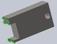
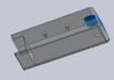
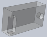
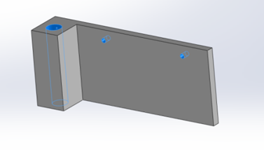
Once the functional surfaces have been identified and the geometric and functional specifications accounted for, the functional volume that encompasses these surfaces is illustrated in Figure 13. The functional area is represented in gray, while other colors indicate the additional parts of the system.
Figure 13. Functional volume
At this stage, the specifications can be converted into specific objectives:
Figure 14. Integration of functional constraints
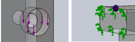
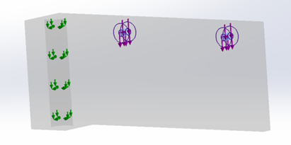
The second step involves incorporating the boundary conditions and the mechanical stresses to be applied to the component. The primary support is located at the mounting pivot. According to the specifications, a load of 100 N is applied to the surface in contact with the screen at the screw holes, considering the offset of the case's center of gravity in relation to these screw holes, as shown in Figure 14.
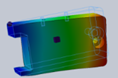
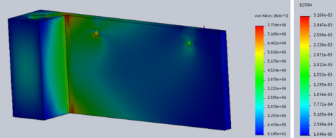
The next step is to analyze the weight and performance of the first original volume. The mass is 47 grams, with a target of 23.5 g. The maximum Von Mises stress is below the material limit, as shown in Figure 15.
Figure 15. Stress and strain results for the original part
At this point in the methodology, the component does not meet the resistance criteria established by the specifications for PLA material. The calculated stress is 7.75 MPa, and the strain is 3.18×10⁻³.
The next step is to address the primary objective of the specifications, which is to decrease manufacturing costs by minimizing both the weight of the part and the manufacturing time. This is achieved through topology studies utilizing the following data set:
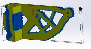
The outcome of this optimization process is illustrated in Figure 16, where the stress is recorded at 1.24 MPa, and the strain is measured at 0.14×10⁻³.
Figure 16. Topological optimization results (stress and strain)
To conduct this study, the following parameters are specified, as shown in Figure 17.
Figure 17. Topological optimization data
The volumetric body that fulfills the functional requirements outlined in the specifications
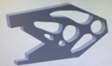
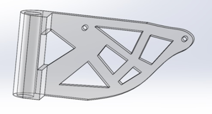
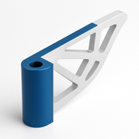
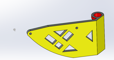
The resulting part meets the specifications; however, it is not suitable for printing. Therefore, a redesign of the volume is necessary to achieve a smoother surface finish. The outcome of this redesign is illustrated in Figure 18.
Figure 18. Redesign of topological optimization result
A verification of the obtained volume is essential prior to advancing to the subsequent stage in Figure 19. The mass is recorded at 26.61 g, and the following static analysis confirms the validity of the solution at this phase, with a stress of 1.13 MPa and a strain of 3.85×10⁻⁴.
Figure 19. Stress and strain study of the redesign result
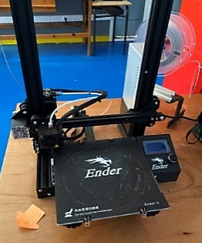
The subsequent step in the methodology involves selecting the appropriate manufacturing process. The material recommended for this application is PLA. The specifications do not necessitate high mechanical properties, precision, or heat resistance, making Fused Deposition Modeling (FDM) the most suitable process for several reasons:
Figure 20. 3D printer used
The subsequent step involves incorporating the constraints associated with the manufacturing process and machine, commencing with an assessment of the thickness limits. The thickness optimization phase relies on machine specifications regarding nozzle diameter, layer thickness, and achievable overhang angle.
Research indicates that the optimal thicknesses for the Fused Deposition Modeling (FDM) process are three times the nozzle diameter for minimum thickness and equal to the nozzle diameter for layer thickness to ensure adequate mechanical performance. To enhance manufacturing cost-efficiency and speed, the maximum thickness should be ten times the nozzle diameter [26]. For this application, the derived data are as follows:
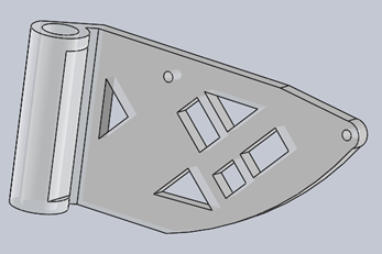
Figure 21 illustrates the results obtained from the software after integrating the specified thickness targets. There are ten instances of non-compliance with the established rules, of which nine relate to exceeding the maximum thickness, and one pertains to failing to meet the minimum thickness requirement in Figure 21.
Figure 21. Thickness control illustration
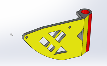
The component is subsequently optimized through manual adjustments, which involve adding or removing material in the designated areas. The outcome of this optimization is presented in Figure 22.
Figure 22. Validated part in terms of thickness
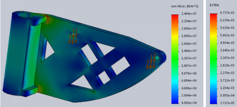
At this stage, a new static analysis is necessary to verify that the specifications continue to be satisfied in Figure 23. The resulting mass is 19.82 g, and the mechanical performance aligns with the anticipated criteria, with a stress of 2.4 MPa and a strain of 6.73×10⁻⁴.
Figure 23. Study of thickness control results (stress and strain)
At this stage of the methodology, the solution obtained adheres to the defined design domain. The next objective is to optimize the amount of support required for the manufacturing process and the associated machine. To achieve this, the methodology employs software tools to identify areas necessitating support and to explore strategies for minimizing this support, thereby fulfilling two key criteria outlined in the specifications. The first criterion aims to reduce the volume of material utilized, while the second seeks to decrease the finishing time, ultimately shortening the overall production duration of the completed part.
Initially, the manufacturing orientation must satisfy two essential conditions:
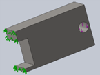
Figure 24. Result of overhang angle analysis
Once the manufacturing orientation has been determined, the software highlights the areas requiring support, as indicated in red in the subsequent feature, as shown in Figure 24.
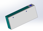
The subsequent step involves adjusting the angles to reduce the overhanging regions that will necessitate support. The modified part is illustrated in Figure 25.
Figure 25. Result of optimizing overhang angles
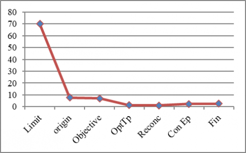
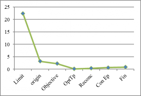
Table 6. Retrieved data
|
Part |
Mass [g] |
Resistance [MPa] |
Strain [10-3] |
|
Limit Origin Objective Topo optimization Redesign Thickness control Final part |
47 47 23.5 22.4 26.61 19.82 19.24 |
70 7.75 7 1.24 1.13 2.4 2.62 |
22.4 3.18 2.24 0.14 0.38 0.673 0.855 |
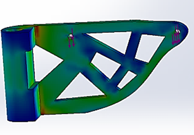
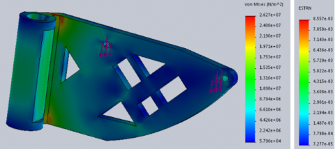
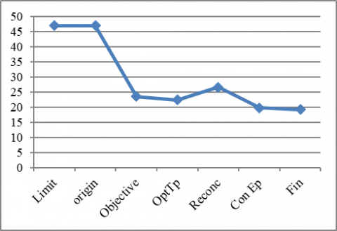
A final analysis is essential to confirm adherence to the specifications and the defined process domain, shown in Table 6. The modified part has a mass of 19.24 g, and the mechanical performance metrics presented in Figure 26 and Figure 27 align with the specifications. The stress recorded is 2.62 MPa, while the strain is measured at 0.855×10⁻³.
Figure 26. Results of final part study (stress and strain)
Figure 27. Graph results for mass [g], resistance [MPa] and strain
At this stage, the methodology's objectives have been successfully accomplished. The resulting model adheres to the specifications, fulfills the optimization goals, is compatible with the Fused Deposition Modeling (FDM) process, and is tailored for the specific Ender 3 printing machine, complete with a predetermined manufacturing orientation. The user can now export the model in STL format and utilize appropriate preparation software for the selected machine to produce the corresponding G-code for fabrication.
The analysis of existing methodologies has enabled the author to establish the foundational principles for a comprehensive approach to additive manufacturing (AM) component design. This methodology is characterized by a direct, opportunity-driven approach that refrains from imposing preconceived notions on the model to be developed, while capitalizing on the advantages inherent to AM. The proposed framework facilitates a modular and integrated process, allowing for rapid iterations across various stages, thereby enabling straightforward modifications to model parameters for optimization purposes.
By incorporating machine and manufacturing process data at the earliest possible point in the value chain, the methodology significantly enhances both time and cost efficiency. It is rooted in a thorough analysis of the current state of the art, integrates theoretical concepts of the design process, and leverages the strengths of traditional design techniques, supplemented by additional benefits. Furthermore, it provides modeling strategies that harness the complexity of the AM process, facilitating the effective integration of manufacturing preparation within the design workflow. To minimize disruptions in the digital chain, the methodology includes a software application that consolidates each phase of the process into a single, cohesive tool.
The final section presents a proof of concept that underscores the added value of the methodology. The author selected a component with specifications encompassing multiple constraints and, without preconceiving the design, utilized the methodology to develop an optimized model suitable for the Fused Deposition Modeling (FDM) process while establishing an effective manufacturing strategy. The article delineates the methodology's step-by-step progression, beginning with the identification of the functional volume that satisfies the specifications, followed by the definition of the initial design volume, which is subsequently evaluated from a static perspective. This is succeeded by an optimization phase aimed at meeting the established objectives. The resulting volume underwent redesign to enhance surface finishing. The subsequent step involved selecting the appropriate manufacturing process and machine. The parameters from this phase were employed to compare the obtained geometry against the process requirements and to determine the optimal orientation. Finally, the resultant design was re-evaluated and confirmed to align with the functional objectives and ensure manufacturability with the selected process and machine.
[1] Bourell, D.L., Leu, M., Rosen, D. (2009). Roadmap for additive manufacturing: Identifying the future of freeform processing. University of Texas at Austin Labratory for Freeform Fabrication Advanced Manufacturing Center.
[2] Blanther, J.E. (1892). Manufacture of contour relief-maps.
[3] Gibson, L.J. (2005). Biomechanics of cellular solids. Journal of Biomechanics, 38(3): 377-399. https://doi.org/10.1016/j.jbiomech.2004.09.027
[4] Wohlers, T. (2011). Wohlers report 2011: Additive manufacturing and 3D printing: State of the Industry: Annual worldwide progress report. Wohlers Associates.
[5] Dilberoglu, U.M., Gharehpapagh, B., Yaman, U., Dolen, M. (2017). The role of additive manufacturing in the era of industry 4.0. Procedia Manufacturing, 11: 545-554. https://doi.org/10.1016/j.promfg.2017.07.148
[6] Rodrigue, H., Calatoru, V., Richir, S., Rivette, M. (2011). Une méthodologie de conception pour la fabrication additive. Congrès International de Génie Industriel, Canada.
[7] Comb, J., Priedeman, W., Turley, P.W. (1994). FDM® Technology process improvements.
[8] Kafle, A., Luis, E., Silwal, R., Pan, H.M., Shrestha, P.L., Bastola, A.K. (2021). 3D/4D printing of polymers: Fused deposition modelling (FDM), selective laser sintering (SLS), and stereolithography (SLA). Polymers, 13(18): 3101. https://doi.org/10.3390/polym13183101
[9] Yadav, P., Rigo, O., Arvieu, C., Le Guen, E., Lacoste, E. (2020). In situ monitoring systems of the SLM process: On the need to develop machine learning models for data processing. Crystals, 10(6): 524. https://doi.org/10.3390/cryst10060524
[10] Ziaee, M., Crane, N.B. (2019). Binder jetting: A review of process, materials, and methods. Additive Manufacturing, 28: 781-801. https://doi.org/10.1016/j.addma.2019.05.031
[11] Ahn, D.G. (2021). Directed energy deposition (DED) process: State of the art. International Journal of Precision Engineering and Manufacturing-Green Technology, 8(2): 703-742. https://doi.org/10.1007/s40684-020-00302-7
[12] Gülcan, O., Günaydın, K., Tamer, A. (2021). The state of the art of material jetting—A critical review. Polymers, 13(16): 2829. https://doi.org/10.3390/polym13162829
[13] Gibson, I., Rosen, D.W., Stucker, B., Gibson, I., Rosen, D.W., Stucker, B. (2010). Sheet lamination processes. In Additive Manufacturing Technologies: Rapid Prototyping to Direct Digital Manufacturing. Springer, Boston, MA., pp. 223-252. https://doi.org/10.1007/978-1-4419-1120-9_8
[14] Rashid, M., Sabu, S., Kunjachan, A., Agilan, M., Anjilivelil, T., Joseph, J. (2024). Advances in wire-arc additive manufacturing of nickel-based superalloys: Heat sources, DfAM principles, material evaluation, process parameters, defect management, corrosion evaluation and post-processing techniques. International Journal of Lightweight Materials and Manufacture, 7(6): 882-913. https://doi.org/10.1016/j.ijlmm.2024.05.009
[15] Boyard, N., Rivette, M., Christmann, O., Richir, S. (2013). A design methodology for parts using additive manufacturing. In 6th International Conference on Advanced Research in VIRTUAL and Rapid Prototyping, London, pp. 399-404.
[16] Bendsøe, M.P., Kikuchi, N. (1988). Generating optimal topologies in structural design using a homogenization method. Computer Methods in Applied Mechanics and Engineering, 71(2): 197-224. https://doi.org/10.1016/0045-7825(88)90086-2
[17] Ponche, R., Kerbrat, O., Mognol, P., Hascoet, J.Y. (2014). A novel methodology of design for additive manufacturing applied to additive laser manufacturing process. Robotics and Computer-Integrated Manufacturing, 30(4): 389-398. https://doi.org/10.1016/j.rcim.2013.12.001
[18] Laverne, F., Segonds, F., Anwer, N., Le Coq, M. (2015). Conception pour la fabrication additive: Un état de l'art. Presentedat the AIP PRIMECA'15, La Plagne, France.
[19] 3D Hubs. (2016). https://www.3dhubs.com/knowledge-base/cad-modeling-1-enclosures.
[20] Eduscol Education. https://sti.eduscol.education.fr/sites/eduscol.education.fr.sti/files/ressources/pedagogiques/5349/5349-ressources-ces-edupack.pdf.
[21] Bendsøe, M.P. (1989). Optimal shape design as a material distribution problem. Structural Optimization, 1: 193-202. https://doi.org/10.1007/BF01650949
[22] Salem, H., Abouchadi, H., Elbikri, K. (2022). PLA mechanical performance before and after 3D printing. International Journal of Advanced Computer Science and Applications, 13(3): 324-330. https://doi.org/10.14569/IJACSA.2022.0130340
[23] Aoussat, A. (1990). La pertinence en innovation: Nécessité d’une approche plurielle. Laboratoire Conception de Produits et Innovation.
[24] Boualaoui, A., Sarsri, D., Lamrhari, M. (2024). Case of topological optimisation of a part produced by the FDM process. Journal of Achievements in Materials and Manufacturing Engineering, 122(1): 5-13.
[25] CORE77 Homepage. (2024). https://www.core77.com/.
[26] Zharylkassyn, B., Perveen, A., Talamona, D. (2021). Effect of process parameters and materials on the dimensional accuracy of FDM parts. Materials Today: Proceedings, 44: 1307-1311. https://doi.org/10.1016/j.matpr.2020.11.332