Lokesh Bhardwaj![]()
© 2025 The author. This article is published by IIETA and is licensed under the CC BY 4.0 license (http://creativecommons.org/licenses/by/4.0/).
OPEN ACCESS
Multiple-input-multiple-output (MIMO) techniques and effective precoding algorithms are required due to the inherent difficulties of Millimeter-Wave (mmWave) propagation. The challenges include the significant route loss due to high-frequency usage. Further, the sparse channel matrix yields improper channel estimation (CE), resulting in erroneous reception, which limits the implementation of mmWave technology. Therefore, beam formation is required to direct the power in the direction of the user by exploiting the spatial multiplexing of MIMO. The above-stated limitations, along with hardware constraints of using a lesser number of radio frequency (RF) chains, can be mitigated through effective precoding at the transmitter. The efficient utilization of mmWave bandwidth by users is crucial for a spectrally efficient system, as it helps conserve this scarce resource. Hence, this study has examined the spectral efficiency (SE) of mmWave MIMO systems for various precoding strategies, including minimum mean-square estimation (MMSE) precoding, fully digital and hybrid zero-forcing (ZF) precoding, and analog beamforming. The performance in terms of achievable SE has been studied considering variability in the user base and the number of transmit and receive antennas. Simulation results have been presented, showing that the MMSE precoder outperforms the ZF precoder. Furthermore, the dominant fully digital MMSE precoder approaches the SE of single-user MIMO as the number of users increases, compared to the fully digital ZF precoder.
spectral efficiency, multiple-input-multiple-output, minimum mean square estimation, millimeter-wave, millimeter-wave multiple-input-multiple-output
The search for new frequency bands and cutting-edge communication technologies has been driven by the rapid growth of wireless data traffic and the increasing demand for faster transmission speeds. Frequency bands in the RF region are utilized for various purposes, including satellite communication, radio communications, television broadcasting, and more. Being high-band fifth-generation (5G), this range works best across shorter distances in highly dense environments. 5G mmWave offers the fastest speeds and the maximum capacity, enabling advanced technologies such as automated cars.
The two main subjects of the feasibility of mmWave spectrum are its ability to support users on the go and its reach. On both points, new developments and antenna technologies are pushing the envelope. For instance, autonomous cars can communicate with other vehicles using the 5G mmWave frequency to steer clear of traffic and obstacles. Because it can support very high data rates and large bandwidths, mmWave communication, which operates in the 30–300 GHz range, has emerged as a promising contender for future wireless systems [1-7]. Rappaport et al. [8] discussed the feasibility of using mmWave communication for mobile applications, highlighting the significant path loss and the requirement for directional beamforming to achieve system reliability. El Ayach et al. [9] examined the basis pursuit, which can be used to construct precoders that are limited by hardware constraints and can be applied by realistic mmWave transceivers. According to Payami et al. [10], a fully digital precoding provides the most flexibility by regulating the amplitude and phase of the transmitted signals at each antenna.
However, because it requires numerous costly and power-hungry RF chains, its application at mmWave wavelengths is challenging. Analog and hybrid precoding systems were developed to overcome these constraints. Alkhateeb and Heath [11] suggested that such precoders offer less control over spatial multiplexing, while analog precoding uses a network of phase shifters to reduce hardware complexity. Hybrid precoding architectures strike a balance between performance and complexity by integrating analog beamforming with a limited number of RF links. Du et al. [12] proposed a convolutional neural network-based precoder to enhance SE and energy efficiency with minimal delay. Ma et al. [13] proposed a deep learning-based CE and feedback scheme for reducing overhead in mmWave MIMO systems. Kebede eta al. [14] have discussed the impact of fully connected and partially connected hybrid architecture on the performance of the mmWave MIMO system. Albreem et al. [15] have proposed a machine learning-based non-linear precoding scheme to estimate features such as the peak-to-average power ratio and constant envelope. Reddy et al. [16] have reviewed various algorithms for CE and hybrid precoding to analyze the performance of the latest communication technologies. Khalid et al. [17] have suggested that selecting a transmit antenna using an optimized algorithm based on probability distribution learning can yield a solution that provides selective antennas in real-time, thereby enhancing SE. Samir et al. [18] have estimated and proposed a low-complexity performance for mmWave MIMO systems using orthogonal matching pursuit and MMSE precoding techniques. Liu et al. [19] have optimized the sum SE using discrete Fourier transform in digital and analog precoders. Alkhateeb et al. [20] have compared precoding techniques at low and mmWave frequencies. Based on the comparison, hybrid analog-to-digital precoding techniques have been proposed. Yu et al. [21] have proposed a hybrid precoder design optimization that can be applied to both fully connected and partially connected architectures, utilizing an effective alternating minimization process. This approach demonstrates a performance gain over current hybrid precoding schemes. Businesses can now achieve unparalleled performance and network management with an independent 5G system. 5G mmWave is essential for applications that can benefit from connectivity via public mobile networks, as it offers focused, high-performance service for moving cars, customers, and devices throughout urban areas. Although computer aficionados tend to experience more problems, perhaps due to their higher expectations, there is a slight variation in how each views the utility of connectivity in crowded areas. It is crucial to acknowledge that each group places a higher value on packed area connectivity than coverage and indoor connectivity. Guo et al. [22] have proposed a robust sum mean square error scheme for designing precoders, which shows a considerable improvement in the form of reduced bit error rate for low transmission power. Shahjehan et al. [23] thoroughly analyzed the basis of scattering, network, link, and codebook for the design optimization of mmWave MIMO systems.
When it comes to meeting increased data demands, mmWave spectrum can be quite helpful. However, even if mmWave 5G can provide high-end experiences, its capacity to generate income must also be taken into account. Kabalci et al. [24] have proposed a decomposition technique based on the geometric mean, which provides a significant improvement in the performance of mmWave MIMO systems.
Jafri et al. [25] have proposed hybrid beam formers based on asynchronous distribution to reduce transmission power, even when channel state information is uncertain at the transmission end.
SE is the effective transmission of the data using the allocated bandwidth. Bandwidth is a valuable resource, and all commercial wireless applications must adhere to its usage as per the guidelines set by the International Telecommunication Union. In a mmWave MIMO system, the spatial multiplexing provides the flexibility of using the same bandwidth by multiple users. If the information of such users is separated with minimum and acceptable errors, the throughput is said to be achieved. This results in a spectrally efficient system. Hence, the SE is a crucial factor examined in this work for the effective reception of signals. Since a lesser number of RF chains is employed compared to the number of users, efficient precoding techniques are required to achieve the SE, which in turn provides massive connectivity.
The increase in SE would benefit practical applications that require high capacity and very low latency, such as mobile communication scenarios, where the actual network is connected to small cells. Furthermore, indoor wireless access can be provided with very high data rates, which can match the data rates of wired communication systems. Furthermore, vehicle-to-vehicle communication, where line-of-sight propagation is essential, is a key outcome of the mmWave MIMO system with high SE.
The objectives of the study:
The simulations in this study limit the number of users to 10, while varying the initial value from 5 for the fixed number of transmit and receive antennas. The number of transmit and receive antennas is fixed to 16.
Thereafter, the number of transmit and receive antennas is varied from 25 to 36 for a fixed number of users. Further, the CE employed in this work is based on directional cosine vectors at the transmitter and receiver ends. A significantly less sparse channel is considered, which results in fewer multipath components.
Contributions of the paper:
1. An improvement in the SE of mmWave MIMO systems has been presented, considering both hybrid and fully digital precoders.
2. The effect of the variation in the user base on the SE has been analyzed and shown for a fixed number of transmit and receive antennas.
3. The effect of varying the number of transmit and receive antennas on the SE has been analyzed and illustrated for a fixed number of users.
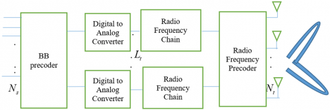
The number of $M$ antennas and $K$ users in a single base station (BS) have been considered for a multi-user hybrid mmWave MIMO system. To serve $K$ users, the BS has a $N_{R F}$ number of RF chains. The $M$ phase shifters are used to connect each RF chain to $M$ number of antennas. At the BS, the number of phase shifters is $M \times N_{R F}$.
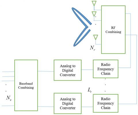
The channel in the mmWave model is sparse; however, the line-of-sight component exists alongside other elements in an urban environment. The system model of hybrid precoding and combining for mmWave MIMO systems has been presented in Figures 1 and 2, respectively.
Figure 1. Hybrid digital-to-analog precoding for mmWave MIMO system
Figure 2. Hybrid analog-to-digital combining for mmWave MIMO system
2.1 mmWave channel model
The channel modelling for the mmWave MIMO system is given by Eq. (1).
$\mathbf{Q}=\sum\limits_{l=1}^{L}{{{\beta }_{l}}{{\mathbf{\kappa }}_{R}}({{\varphi }_{l}}^{r})\mathbf{\kappa }_{T}^{H}({{\varphi }_{l}}^{t})}$ (1)
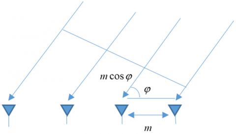
Every path $l$ is represented by the arrival angle $\varphi_l{ }^r$, departure angle $\varphi_l{ }^t$ and the complex gain $\beta_l . \boldsymbol{\kappa}_R\left(\varphi_l{ }^r\right)$ and $\boldsymbol{\kappa}_T\left(\varphi_l{ }^t\right)$ show the directional cosine vectors (DCVs) of the $l^{\text {th }}$ integrant at receiver and transmitter, respectively.
Figure 3. DCV of lth multipath component at the receiver end
$L$ is the number of multipath components. DCV for the lth multipath component is depicted in Figure 3.
The modeling of the channel, as provided by Eq. (1), is modified and presented in Eq. (2).
$\mathbf{Q}=\sum\limits_{l=1}^{L}{{{\beta }_{l}}{{\mathbf{\kappa }}_{R}}({{\varphi }_{l}}^{r})\mathbf{\kappa }_{T}^{H}({{\varphi }_{l}}^{t})}=\left[ \begin{matrix} {{\mathbf{\kappa }}_{R}}({{\varphi }_{1}}^{r}) & {{\mathbf{\kappa }}_{R}}({{\varphi }_{2}}^{r}) & \cdots & {{\mathbf{\kappa }}_{R}}({{\varphi }_{L}}^{r}) \\\end{matrix} \right]\times \left[ \begin{matrix} {{\beta }_{1}} & \ldots & 0 \\ \vdots & \ddots & \vdots \\ 0 & \cdots & {{\beta }_{L}} \\\end{matrix} \right]\left( \begin{matrix} \mathbf{\kappa }_{T}^{H}({{\varphi }_{1}}^{t}) \\ \mathbf{\kappa }_{T}^{H}({{\varphi }_{2}}^{t}) \\ \vdots \\ \mathbf{\kappa }_{T}^{H}({{\varphi }_{L}}^{t}) \\\end{matrix} \right)$ (2)
3.1 Hybrid precoder for mmWave MIMO system
Eq. (3) describes the precoded signal vector c in a MIMO system.
$\mathbf{c}={{\mathbf{E}}_{BB}}\mathbf{p}$ (3)
where, $\boldsymbol{E}_{B B}$ is the BB precoder at the transmitting end. $\mathbf{p}$ is $N_t \times 1$ symbol vector. The signal received is provided in Eq. (4).
$\mathbf{\tilde{z}}=\mathbf{Qc}+\mathbf{n}=\mathbf{Q}{{\mathbf{E}}_{BB}}\mathbf{p}+\mathbf{n}$ (4)
where, $\mathbf{Q}$ is $N_r \times N_t$ channel matrix and $\mathbf{n}$ is $N_r \times 1$ noise vector.
The channel matrix Q is decomposed using singular value decomposition (SVD) as follows:
$\boldsymbol{Q}=\boldsymbol{\chi} \boldsymbol{\psi} \boldsymbol{\zeta}^H$, where $\boldsymbol{\chi}$ is $N_r \times N_t$ combiner matrix and $\boldsymbol{\zeta}^H$ is $N_t \times N_t$ precoder matrix. $\boldsymbol{\psi}$ is a diagonal matrix with non-negative singular values. As $N_s$ symbols need to be transmitted, $\boldsymbol{\psi}$ and $\boldsymbol{\zeta}$ are partitioned as given by Egs. (5) and (6), respectively.
$\mathbf{\Psi }=\left( \begin{matrix} {\mathbf{\bar{\Psi }}} & 0 \\ 0 & {\mathbf{\tilde{\Psi }}} \\\end{matrix} \right)$ , $\mathbf{\bar{\Psi }}={{N}_{s}}\times {{N}_{s}}$ (5)
${{\mathbf{\zeta }}^{H}}=\left( \begin{matrix} {{{\mathbf{\bar{\zeta }}}}^{H}} \\ {{{\mathbf{\tilde{\zeta }}}}^{H}} \\\end{matrix} \right)$ , ${{\mathbf{\bar{\zeta }}}^{H}}={{N}_{s}}\times {{N}_{t}}$ (6)
Therefore, the BB precoder for the conventional MIMO system is set to $\bar{\zeta}$.
Both BB and RF precoders must be designed for the mmWave MIMO system. We know, $\boldsymbol{E}_{B B}=\overline{\boldsymbol{\zeta}}$ is $N_t \times N_s \mathrm{BB}$ precoder matrix and $\boldsymbol{E}_{R F}=\overline{\boldsymbol{I}}$ is $N_t \times N_t \mathrm{RF}$ precoder identity matrix in MIMO system. But, this is not feasible in the mmWave MIMO system as $\boldsymbol{E}_{B B}$ has to be of size $N_{R F} \times N_s$ and can produce only $N_{R F}$ outputs. The optimal precoder $\overline{\boldsymbol{\zeta}}$ should be $\boldsymbol{E}_{R F} \boldsymbol{E}_{B B}$. So, the equivalent optimization problem for finding the optimal precoder is $\operatorname{argmin}\left\|\overline{\boldsymbol{\zeta}}-\boldsymbol{E}_{R F} \boldsymbol{E}_{B B}\right\|_F^2$.
For the mmWave MIMO, the channel matrix is:
$\mathbf{Q}={{\mathbf{\bar{\kappa }}}_{R}}{{\mathbf{Q}}_{b}}{{\mathbf{\bar{\kappa }}}_{T}}_{T}^{H}=\mathbf{\chi \psi }{{\mathbf{\zeta }}^{H}}$ (7)
Eq. (7) can be rewritten as $\boldsymbol{Q}^H=\overline{\boldsymbol{\kappa}}_T \boldsymbol{Q}_b \overline{\boldsymbol{\kappa}}_R^H=\boldsymbol{\zeta} \boldsymbol{\psi}^H \boldsymbol{\chi}^H$. The transmit array response vectors in ${{\mathbf{\bar{\kappa }}}_{T}}$ provide a basis for the column space of $\boldsymbol{Q}^H$. The space of columns in $\boldsymbol{Q}^H$ includes the column of $\boldsymbol{\zeta}$. Hence, the modelling of the precoder is given by Eq. (8).
$\mathbf{\bar{\zeta }}={{\mathbf{\bar{\kappa }}}_{T}}\mathbf{\bar{E}}$ (8)
Combining the columns of $\overline{\boldsymbol{\kappa}}_T$ linearly provides $\overline{\boldsymbol{\zeta}}$.
Since the components of $\overline{\boldsymbol{\kappa}}_T$ are of unit magnitude, $\overline{\boldsymbol{\kappa}}_T$ can be treated as an RF precoder and $\overline{\boldsymbol{E}}$ as a BB precoder. There are $L$ columns in the transmission array response matrix $\overline{\boldsymbol{\kappa}}_T$, which is generally unknown.
So, it can be concluded that a linear combination of $N_{R F}$ columns of $\overline{\boldsymbol{\kappa}}_T$ is possible as the number of non-zero rows in $\overline{\boldsymbol{E}}$ is equal to $N_{R F}$. Therefore, if $N_{R F}<L$, the possibility of determining $\overline{\boldsymbol{\zeta}}$ from $\overline{\boldsymbol{\kappa}}_T$ is negligible. Only $N_{R F}$ columns of $\overline{\boldsymbol{\kappa}}_T$ can be linearly combined since $\overline{\boldsymbol{E}}$ is constituted of only $N_{R F}$ non-zero rows. Hence, $\overline{\boldsymbol{\zeta}}$ cannot be obtained from $\overline{\boldsymbol{\kappa}}_T$ if $N_{R F}<L$.
3.2 A fully digital MMSE precoder
The MMSE precoding scheme has been presented in this section. Creating the transmit precoder, which yields the received signal vector $\widehat{\boldsymbol{g}}$, is the objective of the MMSE precoder.
The received signal vector $\widehat{\boldsymbol{g}}=\left[\begin{array}{llll}\hat{\boldsymbol{g}}_1 & \hat{\boldsymbol{g}}_2 \ldots & \hat{\boldsymbol{g}}_k\end{array}\right]^T$ should approach the actual signal vector $\mathbf{g}$. Using such digital precoding, $N_t \times N_\sigma^{R F}$ precoder can be employed for $\boldsymbol{E}_R \boldsymbol{E}_{B_i}$. At the BS, $\boldsymbol{U}=\left[\begin{array}{llll}\boldsymbol{U}_1 & \boldsymbol{U}_1 \ldots & \boldsymbol{U}_k\end{array}\right]$ is an MMSE precoder and $\eta$ be the power gain factor for matching the power constraint at the BS. $\boldsymbol{E}_i^{M M S E}$, being the fully digital MMSE precoder for the $i^{\text {th }}$ MS is given as $\sqrt{1 / \eta} \boldsymbol{U}_i \boldsymbol{\zeta}_i$, where $\boldsymbol{\zeta}_i$ is the unitary matrix at BS. The baseband equalizer $\boldsymbol{J}_{B_i}$ at ${{i}^{th}}$MS is $\sqrt{\eta \boldsymbol{J}_i} \cdot \boldsymbol{J}_i^*$ is the unitary matrix at MS.
Putting $\boldsymbol{E}_i^{M M S E}$ and $\boldsymbol{J}_{B_i}$ in the received model, the estimated signal vector at the $i^{t h}$ mobile station is given by Eq. (9).
${{\hat{g}}_{i}}=\mathbf{J}_{i}^{*}{{\mathbf{\tilde{H}}}_{i}}{{\mathbf{U}}_{i}}{{\mathbf{\zeta }}_{i}}{{\mathbf{g}}_{i}}+\mathbf{J}_{i}^{*}{{\mathbf{\tilde{H}}}_{i}}\sum\limits_{j\ne 1}^{k}{{{\mathbf{U}}_{j}}{{\mathbf{\zeta }}_{i}}{{\mathbf{g}}_{j}}}+\sqrt{\eta }\mathbf{J}_{i}^{*}{{\tilde{n}}_{i}}$ (9)
The overall signal vector for all mobile stations is given in Eq. (10).
$\mathbf{\hat{g}}={{\mathbf{J}}^{*}}\mathbf{\tilde{H}U\zeta g}+\sqrt{\eta }{{\mathbf{J}}^{*}}\tilde{n}$ (10)
where, $\widetilde{\boldsymbol{H}}=\left[\begin{array}{llll}\widetilde{\boldsymbol{H}}_1^T & \widetilde{\boldsymbol{H}}_2^T \ldots & \widetilde{\boldsymbol{H}}_k^T\end{array}\right]^T$ and $\boldsymbol{U}=\left[\begin{array}{llll}\boldsymbol{U}_1 & \boldsymbol{U}_2 \ldots & \boldsymbol{U}_k\end{array}\right]$.
The mean square error (MSE) cost function is minimized to design the precoder and combiner. The MSE cost function is given in Eq. (11).
$\sum\limits_{i=1}^{k}{E \left[ {{\left\| \mathbf{J}_{i}^{*}{{\mathbf{\zeta }}_{i}}{{\mathbf{g}}_{i}}-{{{\mathbf{\hat{g}}}}_{i}} \right\|}^{2}} \right]}=\left\| {{\mathbf{J}}^{*}}\mathbf{\zeta }-{{\mathbf{J}}^{*}}\mathbf{\tilde{H}U\zeta } \right\|_{F}^{2}+\eta {{\sigma }^{2}}\sum\limits_{i=1}^{k}{\left\{ \mathbf{J}_{i}^{*}{{\mathbf{J}}_{i}} \right\}}$ (11)
The optimization results in the solution as given by Eq. (12).
$\mathbf{U}={{\left( {{{\mathbf{\tilde{H}}}}^{*}}\mathbf{\tilde{H}}+\frac{K{{\sigma }^{2}}}{P}{{\mathbf{I}}_{{{N}_{t}}}} \right)}^{-1}}{{\mathbf{\tilde{H}}}^{*}}$ (12)
$\boldsymbol{J}_i$ and $\boldsymbol{\zeta}_i$ can thus be obtained using SVD.
The optimization problem for approximating the optimal precoder is $\operatorname{argmin} \| \overline{\boldsymbol{\zeta}}-$ $\boldsymbol{E}_{R F} \boldsymbol{E}_{B B} \|_F^2$ so that $\| \operatorname{diag}\left(\widetilde{\mathbf{E}}_{B B} \widetilde{\boldsymbol{E}}^H{ }_{B B} \|_0\right)$ and the number of non-zero rows of $\widetilde{\boldsymbol{E}}_{B B}$ is equal to the number of RF chains. The proposed algorithm returns $\boldsymbol{E}_{R F}$ and $\boldsymbol{E}_{B B}$ required for achieving the SE of the mmWave MIMO system.
$\widetilde{\boldsymbol{E}}_{B B}$ is a block sparse matrix that easily allows simultaneous orthogonal matching pursuit to be implemented. This is a greedy algorithm that chooses the RF beam formed column vectors for constructing $\boldsymbol{E}_{R F}$. It reduces the processing complexity of residue calculation and offers fewer energy requirements due to the sparsity of the channel. A few non-zero rows in the channel matrix enable the algorithm to achieve a significant SE, for which the algorithm is discussed as follows:
Once $\boldsymbol{E}_{R F}$ is initialized as a null matrix and initial residue as ideal precoder, the first column of DCV is correlated with $E_{\text {res }}^{(i-1)}$. In the $i^{\text {th }}$ iteration, the column with maximum correlation with the last residue is determined. Thereafter, the RF precoder is built using $j(i)^{\text {th }}$ column of $\boldsymbol{B}_T$ so that nearest solution to the ideal BB precoder can be obtained. The residue is updated for the $j^{t h}$ iteration, and the process is repeated for $(j+1)^{t h}$ iteration.
$\boldsymbol{E}_{R F}^0=[]$; null matrix initialization
$\boldsymbol{E}_{\text {res }}^0=[\bar{\zeta}]$; ideal precoder setting for primary residue
For $1 \leq i \leq N_{R F}$
$\Gamma=\boldsymbol{B}_T^H E_{\text {res }}^{(i-1)} ; E_{\text {res }}^{(i-1)}$ correlation with $\boldsymbol{B}_T$
$j(i)=\operatorname{argmax}\left[\Gamma \Gamma^H\right]_{l, l}$; evaluation of the maximized correlation
$\boldsymbol{E}_{R F}^i=\left[E_{R F}^{i-1} \mid \boldsymbol{b}_T\left(\theta_{j(i)}\right)\right] ; \boldsymbol{E}_{R F}$ is augmented with $j(i)^{t h}$ column of $\boldsymbol{B}_T$
$\boldsymbol{E}_{B B}^i=\left(\left(\boldsymbol{E}_{R F}^i\right)^H \boldsymbol{E}_{R F}^i\right)^{-1}\left(\boldsymbol{E}_{R F}^i\right)^H \overline{\boldsymbol{\zeta}} ; \boldsymbol{E}_{R F}^i$ update, get the impending value of $\boldsymbol{E}_{B B}^i$
$\boldsymbol{E}_{\text {res }}^i=\frac{\bar{\zeta}-\boldsymbol{E}_{R F}^i \boldsymbol{E}_{B B}^i}{\left\|\bar{\zeta}-\boldsymbol{E}_{R F}^i \boldsymbol{E}_{B B}^i\right\|_F}$; iteration $\$ \mathrm{i} \$$ is updated for $\boldsymbol{E}_{\text {res }}^i$
end for
The algorithm provides $\boldsymbol{E}_{R F}$ and $\boldsymbol{E}_{B B}$ with limits $N_T \times N_{R F}$ and $N_{R F} \times N_s$, respectively.
We consider a mmWave MIMO system with a variable number of users $K$. The sparse channel conditions between the BS and users affect the system's performance. The number of transmit $N_T$ and receive antennas $N_R$ have been fixed when $K$ is varied from 5 to 30 . Both $N_T$ and $N_R$ are fixed at 16 initially. The SE of the system for the variable $K$ with fixed $N_T$ and $N_R$ has been shown in Figure 4.
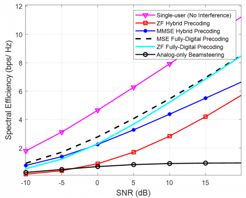
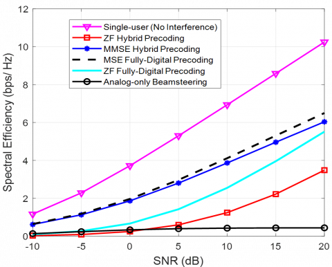
Figure 4. Variation in SE with SNR for $K=5$ and $N_T \& N_R=16$ for hybrid, fully digital, and analog precoders
Figure 4 shows the variation of SE with signal-to-noise ratio (SNR) for analog beamforming, fully digital ZF, fully digital MMSE, hybrid MMSE, and ZF precoders. With an increase in SNR, the MMSE hybrid precoder performs better than its ZF counterpart due to noise amplification in the latter precoder. Fully digital precoders exhibit the same performance at low SNR as hybrid precoders. However, the feasibility of implementing fully digital precoders is limited due to their high complexity, which can result in a slight compromise of SE for hybrid precoders.
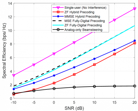
Figure 5. Variation in SE with SNR for $K=10$ and $N_T \& N_R=16$ for hybrid, fully digital, and analog precoders
However, with an increase in $K$ from 5 to 10, it can be observed that the sparsity of the channel further reduces for $N_T \& N_R=16$. It is clear from Figure 5 that the SE is reduced compared to Figure 4.
It can be seen that the SE of the MMSE hybrid precoder approaches the SE of a fully digital precoder for $K=10$. It can, therefore, be concluded that a slightly higher complex MMSE precoder can be employed when the user base increases. Further, ZF fully digital and hybrid precoders should not be used when $K$ increases.
Figure 6. Variation in SE with SNR for $K=5$ and $N_T \& N_R=25$ for hybrid, fully digital and analog precoders
Corollary to the results discussed above, the hybrid ZF precoder is a better candidate for high SNR when $N_T \& N_R=25$. The overall performance in terms of SE is improved for a higher number of antennas at both the transmit and receive ends. Analog beamforming only supports a single user at a time, and therefore, SE remains low irrespective of a change in $N_T \& N_R$. The RF phase shifters employed for RF precoding at the transmitter shift the phase of the incoming signal from each RF chain. The output signals of all phase shifters are combined to form the resulting signals that are transmitted from each transmit antenna. The reduction in $N_{R F}$ provides a way for the effective implementation of mmWave MIMO systems, for which a graphical analysis of SE has been provided in this work.
As $N_T \& N_R$ increase in mMIMO system, the already low sparsity of the channel improves gradually. Hence, the SE also improves as the signal-to-interference and noise ratio at the BS increases, since the pairwise channel vectors approach orthogonality. The improvement when $N_T \& N_R=25$ for $K=5$ has been shown in Figure 6. Moreover, with a further increase in $N_T \& N_R$, the variation in SE with SNR is depicted in Figure 7.
Figure 7. Variation in SE with SNR for $K=5$ and $N_T \& N_R=36$ for hybrid, fully digital and analog precoders
The mmWave MIMO system promises ultra-high-speed communication in the backhaul, where a highly dense and cluttered environment is considered. ZF and MMSE precoding techniques have been considered in both fully digital and hybrid modes. The performance of these precoders is compared with that of a single user with no interference. Furthermore, the performance of the standalone analog beamforming technique is also demonstrated. It has been shown that for a fixed number of users, the SE of the fully digital MMSE precoder is better than that of its ZF counterpart. However, due to practical implementation constraints, hybrid MMSE can be employed when the number of transmit and receive antennas increases. However, when the user base increases with the fixed number of transmit and receive antennas, it has been shown that overall SE reduces. The key outcome is the improvement in the performance of the hybrid MMSE precoder over the fully digital ZF precoder, leading to a further increase in the user base.
[1] Xiao, M., Mumtaz, S., Huang, Y., Dai, L., Li, Y., et al. (2017). Millimeter wave communications for future mobile networks. IEEE Journal on Selected Areas in Communications, 35(9): 1909-1935. https://doi.org/10.1109/JSAC.2017.2719924
[2] Wang, X., Kong, L., Kong, F., Qiu, F., Xia, M., Arnon, S., Chen, G. (2018). Millimeter wave communication: A comprehensive survey. IEEE Communications Surveys & Tutorials, 20(3): 1616-1653. https://doi.org/10.1109/COMST.2018.2844322
[3] Niu, Y., Li, Y., Jin, D., Su, L., Vasilakos, A.V. (2015). A survey of millimeter wave communications (mmWave) for 5G: Opportunities and challenges. Wireless Networks, 21: 2657-2676. https://doi.org/10.1007/s11276-015-0942-z
[4] Seker, C., Güneser, M.T., Ozturk, T. (2018). A review of millimeter wave communication for 5G. In 2018 2nd International Symposium on Multidisciplinary Studies and Innovative Technologies (ISMSIT), Ankara, Turkey, pp. 1-5. https://doi.org/10.1109/ISMSIT.2018.8567053
[5] Karjalainen, J., Nekovee, M., Benn, H., Kim, W., Park, J., Sungsoo, H. (2014). Challenges and opportunities of mm-wave communication in 5G networks. In 2014 9th International Conference on Cognitive Radio Oriented Wireless Networks and Communications (CROWNCOM), Oulu, Finland, pp. 372-376. https://doi.org/10.4108/icst.crowncom.2014.255604
[6] Wu, D., Wang, J., Cai, Y., Guizani, M. (2015). Millimeter-wave multimedia communications: Challenges, methodology, and applications. IEEE Communications Magazine, 53(1): 232-238. https://doi.org/10.1109/MCOM.2015.7010539
[7] Redondi, A.E., Innamorati, C., Gallucci, S., Fiocchi, S., Matera, F. (2024). A survey on future millimeter-wave communication applications. IEEE Access, 12(2): 133165-133182. https://doi.org/10.1109/ACCESS.2024.3438625
[8] Rappaport, T.S., Sun, S., Mayzus, R., Zhao, H., Azar, Y. (2013). Millimeter wave mobile communications for 5G cellular: It will work!. IEEE Access, 1: 335-349. https://doi.org/10.1109/ACCESS.2013.2260813
[9] El Ayach, O., Rajagopal, S., Abu-Surra, S., Pi, Z., Heath, R.W. (2014). Spatially sparse precoding in millimeter wave MIMO systems. IEEE Transactions on Wireless Communications, 13(3): 1499-1513. https://doi.org/10.1109/TWC.2014.011714.130846
[10] Payami, S., Khalily, M., Araghi, A., Loh, T.H., Cheadle, D., Nikitopoulos, K., Tafazolli, R. (2020). Developing the first mmWave fully-connected hybrid beamformer with a large antenna array. IEEE Access, 8: 141282-141291. https://doi.org/10.1109/ACCESS.2020.3013539
[11] Alkhateeb, A., Heath, R.W. (2016). Frequency selective hybrid precoding for limited feedback millimeter wave systems. IEEE Transactions on Communications, 64(5): 1801-1818. https://doi.org/10.1109/TCOMM.2016.2549517
[12] Du, R., Li, T., Li, L., Lou, X., Duan, Z., Liu, F. (2023). DL-PC algorithm for partially-connected hybrid precoding in massive MIMO systems. Physical Communication, 61: 102203. https://doi.org/10.1016/j.phycom.2023.102203
[13] Ma, X., Gao, Z., Gao, F., Di Renzo, M. (2021). Model-driven deep learning based channel estimation and feedback for millimeter-wave massive hybrid MIMO systems. IEEE Journal on Selected Areas in Communications, 39(8): 2388-2406. https://doi.org/10.1109/JSAC.2021.3087269
[14] Kebede, T., Wondie, Y., Steinbrunn, J., Kassa, H.B., Kornegay, K.T. (2022). Precoding and beamforming techniques in mmWave-massive MIMO: Performance assessment. IEEE Access, 10: 16365-16387. https://doi.org/10.1109/ACCESS.2022.3149301
[15] Albreem, M.A., Al Habbash, A.H., Abu-Hudrouss, A.M., Ikki, S.S. (2021). Overview of precoding techniques for massive MIMO. IEEE Access, 9: 60764-60801. https://doi.org/10.1109/ACCESS.2021.3073325
[16] Reddy, G.N., Ravikumar, C.V., Rajesh, A. (2023). Literature review and research direction towards channel estimation and hybrid pre-coding in mmWave massive MIMO communication systems. Journal of Reliable Intelligent Environments, 9(2): 241-260. https://doi.org/10.1007/s40860-022-00174-5
[17] Khalid, S., Mehmood, R., Abbas, W.B., Khalid, F., Naeem, M. (2021). Probabilistic distribution learning algorithm based transmit antenna selection and precoding for millimeter wave massive MIMO systems. Telecommunication Systems, 76: 449-460. https://doi.org/10.1007/s11235-020-00728-z
[18] Samir, Y.N., Nafea, H.B., Zaki, F.W. (2023). Performance evaluation of spectral efficiency hybrid precoding and combining algorithm for millimeter Wave-MIMO systems. Wireless Personal Communications, 133(3): 1769-1784. https://doi.org/10.1007/s11277-023-10845-y
[19] Liu, Y., Zhang, Q., He, X., Lei, X., Zhang, Y., Qiu, T. (2022). Spectral-efficient hybrid precoding for multi-antenna multi-user mmWave massive MIMO systems with low complexity. EURASIP Journal on Wireless Communications and Networking, 2022(1): 66. https://doi.org/10.1186/s13638-022-02150-2
[20] Alkhateeb, A., Mo, J., Gonzalez-Prelcic, N., Heath, R.W. (2014). MIMO precoding and combining solutions for millimeter-wave systems. IEEE Communications Magazine, 52(12): 122-131. https://doi.org/10.1109/MCOM.2014.6979963
[21] Yu, X., Shen, J.C., Zhang, J., Letaief, K.B. (2016). Alternating minimization algorithms for hybrid precoding in millimeter wave MIMO systems. IEEE Journal of Selected Topics in Signal Processing, 10(3): 485-500. https://doi.org/10.1109/JSTSP.2016.2523903
[22] Guo, J.C., Yu, Q.Y., Sun, W.B., Meng, W.X. (2021). Robust efficient hybrid pre-coding scheme for mmWave cell-free and user-centric massive MIMO communications. IEEE Transactions on Wireless Communications, 20(12): 8006-8022. https://doi.org/10.1109/TWC.2021.3089501
[23] Shahjehan, W., Rathore, R.S., Shah, S.W., Aljaidi, M., Sadiq, A.S., Kaiwartya, O. (2024). A review on millimeter-wave hybrid beamforming for wireless intelligent transport systems. Future Internet, 16(9): 337. https://doi.org/10.3390/fi16090337
[24] Kabalci, Y., Ahmadi, M., Ali, M. (2022). Optimal hybrid precoder design for millimeter-wave massive MIMO systems. Computers and Electrical Engineering, 99: 107746. https://doi.org/10.1016/j.compeleceng.2022.107746
[25] Jafri, M., Srivastava, S., Kumar, S., Jagannatham, A.K., Hanzo, L. (2024). Asynchronous distributed coordinated hybrid precoding in multi-cell mmWave Wireless networks. IEEE Open Journal of Vehicular Technology, 5: 200-218. https://doi.org/10.1109/OJVT.2023.3349151