Maha N. Ismael*![]() | Fatin H. Yahya
| Fatin H. Yahya![]()
© 2024 The authors. This article is published by IIETA and is licensed under the CC BY 4.0 license (http://creativecommons.org/licenses/by/4.0/).
OPEN ACCESS
All of the applications that are used in industrial processes require solutions that have a particular chemical strength of the fluids or chemicals that are being under consideration for analysis. When a full-strength solution is combined with water in the proportions that are needed, it is possible to produce the particular concentrations that are wanted. The regulation of the concentration of hydrogen peroxide which produced in an electrolysis process has been investigated over the course of this article. An examination of the impact that various controllers, such as P, PI, PID, and fuzzy logic controllers, have on the process model is presented in this work with the help of MATLAB/SIMULINK as a simulation program. Using fuzzy logic controllers showed that the rising time dropped to 0.3 seconds and the settling time to 0.4 seconds, with no overshoot or undershoot.
fuzzy logic (FL), PID control, chemical concentration, fuzzy model, ECR
Electrochemical reactors (ECR) are essential in a variety of industrial and environmental processes, serving a crucial function in applications such as energy conversion in fuel cells and effluent treatment in wastewater management systems [1]. These systems are difficult due to their multifarious character, which includes sophisticated electrochemical processes and dynamic interactions among various factors [2]. The complex nature of these reactors represents a significant obstacle in modelling and controlling strategies [3, 4].
Using the development of improved catalysts using methods such as multidisciplinary diversification, transition metal doping, and single-atom catalyst doping, researchers have focused on enhancing the electrical energy produced in electrochemical reactors [5-7]. We began developing electrical improvements because there was a need for more efficient process control systems for electrochemical reactions, which include many interactions and other electrochemical processes. Enhancing the coordination between the method and reactor cascade is crucial for a newly upgraded electrochemical process. Implementing a control system to oversee the electrochemical reactor units is also essential [8-10]. Çıtmacı et al. [11] proposed implementing a feedback control system utilizing appropriate integral (PI) controllers and a hybrid SVR-based state estimation model to address this issue. This quick scenario introduces a proportional integral (PI) controller for the first time, facilitating the implementation of single input single output (SISO) control in a closed Rotating Cylindrical Electrode (RCE). Concluding this study, Çıtmacı et al. [12] employed an RNN model to improve the performance of the SVR model. Connecting the recurrent neural network gas model to different methods for determining product concentration while implementing multiple-input multiple-output control using proportional-integral control techniques in a reverse flow catalytic cracking reactor. Contemporary industrial process control systems include model predictive control (MPC) techniques with traditional control approaches [13]. Model Predictive Control (MPC) is a potent technique for multivariable control that considers process restrictions and nonlinearities [14].
Although the utilization of MPC in electrochemical reactors is limited, it is widely used in several research areas including chemical reactors, battery management, and driverless cars. Richalet [15] thoroughly examined the use of Model Predictive Control (MPC) in a crude oil distillation plant within the petroleum industry. Chavan et al. [16] studied the design of Model Predictive Control (MPC) for a multivariable distillation column. Simulations in MATLAB utilizing the Wood and Berry Model showed superior performance compared to control based on Proportional-Integral (PI). An advanced battery management system was created with the assistance of MPC. This system utilizes electrochemical processes to create energy over an extended period, employing an electrochemical reactor to produce products through electrical reactions. Model predictive control (MPC) was introduced by Pozzi et al. [17] to utilize electrochemical models to address charge imbalance in lithium-ion cells in series; it succeeded in effectively regulating electrochemical systems.
It has been demonstrated that Fuzzy Logic Control (FLC) is an excellent method for controlling systems that are complex, ambiguous, non-linear, or susceptible to change over time [18]. A mathematical model of the control system is not necessary for the implementation of FLC, which may be done with relative ease [19]. The use of fuzzy logic has emerged as one of the most successful methods for the development of sophisticated control systems. There is not much of a complicated explanation for this. Fuzzy logic functions very well when it comes to managing applications since it is able to imitate human decision-making processes and generate accurate responses based on particular or approximate facts. In the field of engineering design techniques, it solves a fundamental requirement that is not provided by purely mathematical approaches (like linear control design) or solely logic-based approaches (like expert systems) in system design. More specifically, it answers a need that is not covered by any of these approaches [20, 21]. The purpose of this study is to investigate the dynamics of the electrochemical reactor, the development of a mathematical model, the derivation of the transfer function, the utilization of conventional controllers to regulate the substance concentration, and the comparison of the performance of these controllers with fuzzy logic approaches. This study's primary topics are reducing the amount of time needed for induction, obtaining the intended value more quickly, and limiting overshoot.
It is more likely that there will be a difference between the set point that was anticipated and the actual output when a proportional controller is used. New equilibrium values are achieved between the process input (the controller's output) and the process output before the error approaches zero, which is the reason why this thing takes place. Now we need to compensate such that the controller's output is proportionate to the integral of the error. The proportional integral control describes this. The output of the controller will keep changing so long as the controller receives an error signal. Consequently, the error signal is zeroed out by the integral of error. The present rate of change, or derivative of the mistake, has to be accounted for by adding one additional term. The term for this type of control is proportionate integral derivative. When the controller is aware of the inaccuracy, it may foresee its future trajectory and make adjustments accordingly.
A universal approximation is a fuzzy system. It is not necessary to have a specific model in order to use a fuzzy controlled systems model. These examples come from the fact that a fuzzy system, which is made up of an action and its result as antecedents and consequents, is the same as both a linear algebra and an abstract algebra. Groups, fields, and rings are all part of abstract algebraic models and systems [22-24].
Vector spaces, state vectors, and transition matrices are all part of the linear algebraic system paradigm. One major advantage of fuzzy system theory is that it may approximate system behavior in cases where analytical or numerical functions are not available. In complex systems, when analytical formulations are lacking, fuzzy systems show great promise for understanding these systems. New, untested systems, as well as those involving human situations (e.g., biological or medical systems), might be considered complex. A theory underlying approximation reasoning—a kind of imperfect reasoning—is the end aim of fuzzy logic [25, 26].
The objective of this study was to analyze and compare the outcomes of fuzzy and PID control in the ECR process related to a dynamic system. The study aimed to explore the effectiveness of dynamic PID- and fuzzy-controlled systems in producing hydrogen peroxide H2O2 by manipulating the concentration of the electrolyte solution potassium hydroxide (KOH). However, when operating conventionally, the discussed system encounters instances of undershoots and overshoots. By incorporating a PID controller into the system, the issue of sudden fluctuations can be resolved. However, the output still exhibits instability. Ultimately, a fuzzy logic controller is used to achieve the desired outcome.
2.1 Materials
The (85% KOH) purchased from Sigma-Aldrich, and the electrolyte solution for each experiment was prepared using deionized water of the utmost grade.
2.2 The electrochemical flow reactor model
When mass transport limits the electrochemical reaction, Eqs. (1) and (2) explain the hydrodynamic model of the electrochemical flow reactor in a laminar domain.
$\rho \frac{d u}{d t}+u \rho(u . \nabla) u=\nabla$ (1)
$\nabla \cdot(\rho u)=0$ (2)
The boundary conditions that are numerically represented by Eqs. (3) to (6) can be used to solve Eq. (1) and (2). Here, Eq. (3) depicts a typical inflow rate at the entrance [27], Eq. (4) the standard stress is the same as the pressure at the discharge [27], The beginning condition is represented by Eq. (6), while the wall contour condition is represented by Eq. (5).
$u=-n$ (3)
$\left[-P I+\mu\left(\nabla u+(\nabla u)^T\right] \tilde{n}=\right.$ (4)
$u=0$ (5)
$P_{\text {init }}=P+P_{\text {hydro }}$ (6)
When the rate of electrochemical reactions is constrained by mass transport, the mass balance given by Eqs. (7) and (8) illustrates how the concentration in a single step of the reactor decreases along its length in a laminar regime.
$N_{H P}=\nabla \cdot\left(-D_i \nabla C_{H P}\right)+u \cdot \nabla C_{H P}$ (7)
$\frac{\partial C_{H P}}{\partial t}+N_{H P}=r_{H P}$ (8)
By taking the boundary conditions into account, we may solve Eqs. (7) and (8). Reactants are introduced to the reactor at a rate equal to the flow rate at which they cross plane z = 0 via combined flow and diffusion, as described by Eqs. (9) and (10) [28]. There is no flow at the reactor's exit, and the starting situation is represented by Eq. (11).
$n \cdot N_{H P}=n \cdot(u)$ (9)
$-n \cdot D_i \nabla C_{H P}=0$ (10)
$C_{0, c}=\nabla C_{H P, 0}$ (11)
2.3 Experimental set up
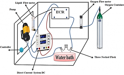
The experimental set up was designed to produce H2O2 in KOH electrolyte solution, as shown in Figure 1. The experimental settings include an electrochemical reactor ECR, a direct current (DC) system, a three-necked flask, a pump, a water bath, oxygen and liquid flow meters, and an oxygen container. A direct current (DC) power supply supplied the necessary voltages for the operation of the ECR. Unreacted oxygen flowed down from the reactor's base into the accumulation flask while the electrolyte at the output created H2O2. The H2O2 concentration was raised by continuously recycling the electrolyte while bubbling unreacted oxygen into the solution and exhausting it. The solution was kept at a constant temperature of 5℃ by submerging the container in a water bath. The concentration of H2O2 produced by applying 0.5V, a liquid flow rate of 1.5 ml min−1 (u = 0.12 m s−1, Re = 1200), and a pH of 7.1, using 0.5 L of synthetic solution. Under these circumstances, deterioration occurs by indirect electrochemical oxidation caused by hydroxyl radicals on the anode surface. The electrochemical action is restricted by the transfer of H2O2 from the bulk to the electrode surface. The electrochemical flow reactor uses two stainless steel plates as an anode and MnO2 nanoparticles as a cathode. It runs in continuous recirculation mode. The procedure lasted 40 minutes and was powered by a DC power supply. Samples were obtained every 5 minutes from the storage tank.
Figure 1. Process diagram
2.4 Inputs and outputs
1. Inputs: Voltage (V) and Concentration of the electrolyte (C).
2. Output: Concentration of the product (P).
2.5 Assumptions
1. Non-linear effects are significant, but the system can be linearized around a specific operating point.
2. Interaction between voltage and concentration is considerable.
3. With regard to concentration, the system exhibits first-order dynamics, while with regard to current; it exhibits second-order dynamics.
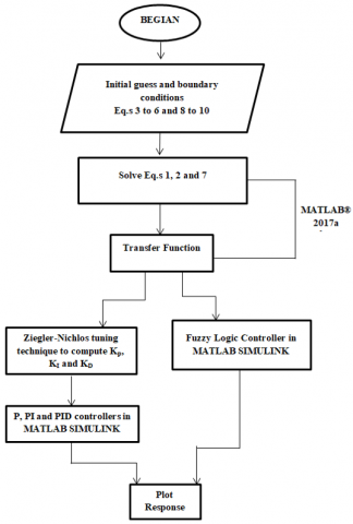
2.6 Numerical solution
Figure 2 shows Schematic representation of the numerical solution for the suggested mathematical model. The whole mathematical model of the electrochemical degradation of Hydrogen Peroxide was solved by implementing partial differential Eqs. (1), (2), and (7) and coupling them with Eq. (11) in MATLAB® 2017a software. Also the transfer function was calculated using MATLAB® 2017a software as follows:
$G(s)=\frac{p(s)}{[V(s), C(s)]}=\left[\frac{k_v s+B_v}{\tau_v^2 s^2+\delta_v s+1} * \frac{k_c}{\tau_c s+1}\right]$ (12)
where:
P(s) is the Laplace transform of the production rate.
$\mathrm{P}(\mathrm{s})$ is the Laplace transform of the production rate.
$\mathrm{V}(\mathrm{s})$ and $\mathrm{C}(\mathrm{s})$ are the Laplace transforms of the voltage and concentration inputs.
$\left(k_v\right)$ and $\left(k_c\right)$ are primary gain factors for the voltage and concentration inputs.
$\left(B_v\right)$ represents a secondary gain related to the voltage input, introducing a zero into the system.
$\left(\tau_v\right),\left(\delta_v\right)$, and $\left(\tau_c\right)$ are time constants associated with the voltage and concentration inputs.
Figure 2 Schematic representation of the numerical solution for the suggested mathematical model
Introducing the experimental values and with Matlab help we found the constants as follows:
$G(s)=\frac{p(s)}{[V(s), C(s)]}=\left[\frac{0.5 s+0.1}{4 s^2+0.05 s+1} * \frac{1.2}{3 s+1}\right]$ (13)
The process has an inverse reaction with delay time and overshoot, which may be observed in this case. The usage of P, PI, and PID controllers to solve this difficulty and get the required response. The controller parameters are computed for this purpose. When it comes to the PID controller, the optimum parameters are the proportional gain (KP), the integral gain (KI), and the differential gain (KD). First, locate and solve the process's characteristic equation. The Ziegler-Nichlos tuning technique was used to determine the parameters of the controllers. These parameters' values are:
$K_p=2, K_I=0.5, K_D=0.1$
We can get the step input response by feeding these numbers into the Simulink PID controller. While there is no overshoot in the output, there is a little inverted response, and the settling and rising times are slightly longer. No, that's not the answer we were hoping for. The next step is to employ the fuzzy logic controller for improved control. A multiplexer is necessary for feeding input signals into a fuzzy logic controller. The controller gets two distinct inputs: error, which represents the disparity between the set point and the output, and feedback, which corresponds to the output itself. Subsequently, construct the input and output membership functions by utilizing triangle memberships. Using the fuzzy rule base editor, we can remove inverted response, overshoot, undershoot, rising time, and settling time by creating fuzzy rules. Our reaction reduces the rising time and settling time to a minimal amount, and there is no undershoot or overshoot. The most challenging aspect of fuzzy control is to get a complete and correct control rule set. Linguistic variables are variables whose values are words not numbers and the numeration is done approximately membership function. The first step of the process is called fuzzification. To perform fuzzy logic reasoning, which is a set of IF–THEN rules that obviously a human-like reasoning must be stated. Another approach is to fuzzily identify using fuzzy identification algorithms [29].
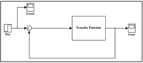
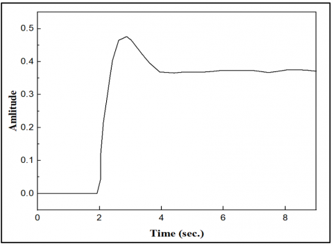
In this part, we present the results of the four times the same experiment was repeated. These four experiments were about the dynamic case where no external changes were made to the setup and the control cases where the voltage and electrolyte concentration were used as the manipulated variables in the use of PID and fuzzy control to achieve the desired amount of the hydrogen peroxide concentration. In the first part, the dynamic behaviour of the system was observed to determine the uncontrolled behaviour of the system and the electrochemical process was carried out without any control action. Figure 3 illustrates the transfer function that depicts the open process without any controller, and Figure 4 shows the output of this process, as we can see that there is a delay time up to 3 sec, and the desired value could not be achieved.
Figure 3. Simulink block diagram of un controlled ECR
Figure 4. Response of un controlled ECR
Figure 5. Simulink block diagram of proportional controller
Figure 6. Response of ECR with proportional controller
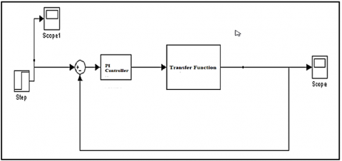
Figure 7. Simulink block diagram of ECR with PI controller
Figure 8. Response of ECR with PI controller
Second part illustrated the effect of proportional and PI controllers on our process. Figures 5, 6, 7, and 8 represent the proportional and PI controller, respectively, with kp and kI equal to 100; the response shows no significant improvement despite a faster response time.
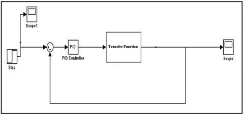
In the next part a PID controller was used as in Figure 9. Controller settings are fine-tuned using the Zeigler and Nichols approach. The rising time, tr = 2 sec., settling time, ts = 4 sec., and overshoot and undershoot were 0%, as shown in Figure 10, where kp, kI, and kD are 2, 0.5, and 0.1, respectively.
Figure 9. Simulink block diagram of ECR with PID controller
Figure 10. Response of ECR with PID controller
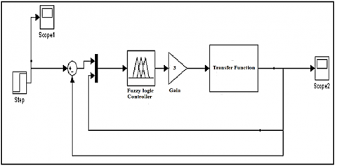
The final part was using Fuzzy rule as in Figure 11 to shorten the settling time; Figure 12 shows that the rising time dropped to 0.3 seconds and the settling time to 0.4 seconds, with no overshoot or undershoot. The usage of fuzzy rules in the modeling and controlling electrochemical reactors has several limitations. Firstly, it may cause the system to become more complicated, thus making the interpretation and maintenance more difficult when the number of rules is increased. The tuning of fuzzy rules is a matter of expertise and time-consuming experimentation that often leads to inferior performance. Besides, fuzzy logic may not always be accurate enough to be used for the precise control in the dynamic and nonlinear electrochemical systems. The problem of being overfitted to a particular dataset can happen which in turn results in the poor generalization and performance on the newly unseen data. The explanation of some decisions that are taken is not so clear, especially when there are a lot of rules. The transition of fuzzy rule-based systems from small or simple reactor systems to larger or more complex reactor systems may encounter some computational problems. The integration of fuzzy logic control with the present system may demand some major modifications, and the adjustment to the changing situations can be tough. Besides, fuzzy logic may not be as efficient as the advanced control techniques like model predictive control, especially in the situations that are highly dynamic. Lastly, the verification and the validation of the correctness and the performance of the fuzzy rule-based control systems are not easy to do because of their extremely complicated and non-deterministic nature.
Table 1 illustrates the main differences between the dynamic process response and the controller strategies used.
Figure 11. Simulink block diagram of ECR with fuzzy controller
Figure 12. Response of ECR with fuzzy controller
Table 1. Comparison between control strategies
|
|
Complexity |
Response |
Overshoot/Undershoot |
Rising Time |
Settling Time |
|
Open process |
Simple |
Slow |
high |
3 sec. |
5 sec. |
|
PID controller |
Simple |
Fast |
non |
2 sec. |
4 sec. |
|
Fuzzy rule |
Complex |
Very Fast |
non |
0.3 sec. |
0.4 sec. |
The study objective was to evaluate the application of an ECR system to produce H2O2 in KOH solution of electrolyte in order to compare the dynamic using PID and fuzzy controller during constant concentration of hydrogen peroxide. The experiments were conducted under 0. 5V, a liquid flow rate of 1.5 ml min−1 (u = 0. 12 m s−1, Re = 1200), with a pH at 7.1, using 0.5 L of artificial liquid. The limits were controlled with both PID and fuzzy methods respectively and fuzzy control followed the set point better than PID control. A precise control over the concentration of H2O2 was achieved.
Depending on the complex model of our electrochemical reactor we found that without control, the process produces an inverted reaction, overshoot, and significant delay time. However, after implementing PID control, the process's inverse response, overshoot, and delay time issues were significantly mitigated; however, the system began to exhibit instability with regard to its rising and settling times. A fuzzy logic controller was employed to rectify this fluctuation in rising and settling times. These lag periods and the graphed inverted response can be eliminated with the aid of the fuzzy control technique. There is a noticeable decrease in both the rise and settling times. Finally, we propose the utilization of the CFD (Computational Fluid Dynamics) programs and others of this kind to simulate and construct the model with more details and more equations by trying to understand the electrolysis process.
|
p |
Density of the fluid kg.L−1 |
|
u |
Liquid flow velocity m s−1 |
|
$\nabla$ |
Gradient |
|
P |
Pressure, Pa |
|
Ι |
Unit momentum vector, dimensionless |
|
μ |
Dynamic viscosity of the fluid, kg m−1 s−1 |
|
F |
Volume force, N m−3 |
|
g |
Gravity acceleration constant, m s−2 |
|
n |
Number of data points |
|
$\tilde{n}$ |
Unit normal vector, dimensionless |
|
Pinit |
Initial pressure, Pa |
|
Phydro |
Hydrodynamic pressure, Pa |
|
Di |
Diffusion coefficient, m2 s−1 |
|
CHP |
Concentration of hydrogen peroxide, mol m−3 |
|
C0 |
Outlet concentration of the hydrogen peroxide from tank |
[1] Lange, R., Schubert, M., Dietrich, W., Grünewald, M. (2004). Unsteady-state operation of trickle-bed reactors. Chemical Engineering Science, 59(22-23): 5355-5361. https://doi.org/10.1016/j.ces.2004.09.007
[2] Satterfield, C.N. (1975). Trickle‐bed reactors. AIChE Journal, 21(2): 209-228. https://doi.org/10.1002/aic.690210202
[3] Roffel, B., Betlem, B. (2007). Process Dynamics and Control: Modeling for Control and Prediction. John Wiley & Sons.
[4] Mahmood, Q.A., Nawaf, A.T., Esmael, M.N., Abdulateef, L.T., Dahham, O.S. (2018). PID temperature control of demineralized water tank. IOP Conference Series: Materials Science and Engineering, IOP Publishing, 454: 012031. https://doi.org/10.1088/1757-899X/454/1/012031
[5] Nitopi, S., Bertheussen, E., Scott, S.B., Liu, X.Y., Engstfeld, A.K., Horch, S., Seger, B., Stephens, I.E.L., Chan, K., Hahn, C., Nørskov, J.K., Jaramillo, T.F., Chorkendorff, I. (2019). Progress and perspectives of electrochemical CO2 reduction on copper in aqueous electrolyte. Chemical Reviews, 119(12): 7610-7672. https://doi.org/10.1021/acs.chemrev.8b00705
[6] Kim, B., Tan, Y.C., Ryu, Y., Jang, K., Abbas, H.G., Kang, T., Choi, H., Lee, K.S., Park, S., Kim, W., Choi, P.P., Ringe, S., Oh, J. (2023). Trace-level cobalt dopants enhance CO2 electroreduction and ethylene formation on copper. ACS Energy Letters, 8(8): 3356-3364. https://doi.org/10.1021/acsenergylett.3c00418
[7] Cao, Y.C., Chen, S.Y., Bo, S.W., Fan, W.J., Li, J.N., Jia, C.M., Zhou, Z., Liu, Q.H., Zheng, L.R., Zhang, F.X. (2023). Single atom Bi decorated copper alloy enables C−C coupling for electrocatalytic reduction of CO2 into C2+ products. Angewandte Chemie International Edition, 62(30): e202303048. https://doi.org/10.1002/anie.202303048
[8] Zheng, T.T., Zhang, M.L., Wu, L.H., Guo, S.Y., Liu, X.J., Zhao, J.K., Xue, W.Q., Li, J.W., Liu, C.X., Li, X., Jiang, Q., Bao, J., Zeng, J., Yu, T., Xia, C. (2022). Upcycling CO2 into energy-rich long-chain compounds via electrochemical and metabolic engineering. Nature Catalysis, 5: 388-396. https://doi.org/10.1038/s41929-022-00775-6
[9] Ozden, A., Wang, Y.H., Li, F.W., Luo, M.C., Sisler, J., Thevenon, A., Rosas-Hernández, A., Burdyny, T., Lum, Y., Yadegari, H., Agapie, T., Peters, J.C., Sargent, E.H., Sinton, D. (2021). Cascade CO2 electroreduction enables efficient carbonate-free production of ethylene. Joule, 5(3): 706-719. https://doi.org/10.1016/j.joule.2021.01.007
[10] Fan, L., Zhao, Y.L., Chen, L., Chen, J.Y., Chen, J.M., Yang, H.Z., Xiao, Y.K., Zhang, T.Y., Chen, J.Y., Wang, L. (2023). Selective production of ethylene glycol at high rate via cascade catalysis. Nature Catalysis, 6: 585-595. https://doi.org/10.1038/s41929-023-00977-6
[11] Çıtmacı, B., Luo, J.W., Jang ,J.B., Canuso, V., Richard, D., Ren, Y.M., Morales-Guio, C.G., Christofides, P.D. (2022). Machine learning-based ethylene concentration estimation, real-time optimization and feedback control of an experimental electrochemical reactor. Chemical Engineering Research and Design, 185: 87-107. https://doi.org/10.1016/j.cherd.2022.06.044
[12] Çıtmacı, B., Luo, J.W., Jang, J.B., Morales-Guio, C.G., Christofides, P.D. (2023). Machine learning-based ethylene and carbon monoxide estimation, real-time optimization, and multivariable feedback control of an experimental electrochemical reactor. Chemical Engineering Research and Design, 191: 658-681. https://doi.org/10.1016/j.cherd.2023.02.003
[13] Qin, S.J., Badgwell, T.A. (2003). A survey of industrial model predictive control technology. Control Engineering Practice, 11(7): 733-764. https://doi.org/10.1016/S0967-0661(02)00186-7
[14] Holkar, K.S., Waghmare, L.M. (2010). An overview of model predictive control. International Journal of Control and Automation, 3(4): 47-63.
[15] Richalet, J. (1993). Industrial applications of model based predictive control. Automatica, 29(5): 1251-1274. https://doi.org/10.1016/0005-1098(93)90049-Y
[16] Chavan, S., Birnale, N., Deshpande, A.S. (2018). Design and simulation of model predictive control for multivariable distillation column. In 2018 3rd IEEE International Conference on Recent Trends in Electronics, Information & Communication Technology (RTEICT), Bangalore, India, pp. 764-768 https://doi.org/10.1109/RTEICT42901.2018.9012517
[17] Pozzi, A., Xie, X., Raimondo, D.M, Schenkendorf, R. (2020). Global sensitivity methods for design of experiments in lithium-ion battery context. IFAC-PapersOnLine, 53(2): 7248-7255. https://doi.org/10.1016/j.ifacol.2020.12.558
[18] Pukrushpan, J.T., Peng, H., Stefanopoulou, A.G. (2002). Simulation and analysis of transient fuel cell system performance based on a dynamic reactant flow model. In ASME International Mechanical Engineering Congress and Exposition, 637-648. https://doi.org/10.1115/IMECE2002-32051
[19] Shin, Y.C., Xu, C. (2017). Intelligent Systems: Modeling, Optimization, and Control. CRC Press. https://doi.org/10.1201/9781420051773
[20] Venkataraman, A. (2021). Design and implementation of adaptive PID and adaptive fuzzy controllers for a level process station. Advances in Technology Innovation, 6(2): 90-105. https://pdfs.semanticscholar.org/ea51/538d335a3677c6d5a92d1db5ff4648c302f2.pdf.
[21] Wang, Y.X., Yu, D.H., Chen, S.A., Kim, Y.B. (2014). Robust DC/DC converter control for polymer electrolyte membrane fuel cell application. Journal of Power Sources, 261: 292-305. https://doi.org/10.1016/j.jpowsour.2014.03.048
[22] Ismael, M.N., Nawaf, A.T., Abdullah, M.A. (2020). Continuous stirred tank reactor using the dual/valve position-cascade control system. International Journal of Mechatronics and Applied Mechanics, (7): 129-137.
[23] Ahmed, D.F., Esmaeel, M.N. (2013). Fuzzy logic control of continuous stirred tank reactor. Tikrit Journal of Engineering Sciences, 20(2): 70-80. https://doi.org/10.25130/tjes.20.2.07
[24] Wang, Y.X., Qin, F.F., Ou, K., Kim, Y.B. (2016). Temperature control for a polymer electrolyte membrane fuel cell by using fuzzy rule. IEEE Transactions on Energy Conversion, 31(2): 667-675. https://doi.org/10.1109/TEC.2015.2511155
[25] Rivero, E.P., Ortega, A., Cruz-Díaz, M.R., González, I. (2018). Modelling the transport of ions and electrochemical regeneration of the resin in a hybrid ion exchange/electrodialysis process for as (V) removal. Journal of Applied Electrochemistry, 48: 597-610. https://doi.org/10.1007/s10800-018-1191-5
[26] Ismael, M.N. (2020). Continuous Stirred Tank Reactor (CSTR) using Mamandi fuzzy control. Journal of Mechanical Engineering Research and Developments, 43(4): 348-359.
[27] Rivera, F.F., León, C.P.D., Walsh, F.C., Nava, J.L. (2015). The reaction environment in a filter-press laboratory reactor: The FM01-LC flow cell. Electrochimica Acta, 161: 436-452. https://doi.org/10.1016/j.electacta.2015.02.161
[28] Mott, H.V., Green, Z.A. (2015). On Danckwerts’ boundary conditions for the plug-flow with dispersion/reaction model. Chemical Engineering Communications, 202(6): 739-745. https://doi.org/10.1080/00986445.2013.871708
[29] Newell, R.B., Lee, P.L. (1989). Applied process control: A case study. Prentice Hall. https://www.amazon.com.au/Applied-Process-Control-Case-Study/dp/0130409405.