OPEN ACCESS
In This paper, we present an experimental study of feedback Linearization applied to regulate the DC bus voltage of three-phase shunt Active Power Filter (APF). The feedback linearization controller is introduced to improve tracking performance characteristics, power quality and minimized consumption of the reactive power. To identify the reference currents we used an algorithm based on the Self Tuning Filter (STF). We generate the firing pulses of the IGBT inverter by using a hysteresis current controller, which is implemented on an analog card. An experimental bench has been implemented. It consists an active filter parallel to IGBTs, a nonlinear a load RL, a dSPACE digital prototyping system (DS1104 development board) for generating the references of the harmonic currents and an analog card to realize the control of harmonic currents by hysteresis. The experimental results under steady state and transient conditions is illustrated with signal-flow graphs and corresponding analysis show the feasibility and the effectiveness of the designed active filter, associated with feedback Linearization controller capability in meeting the IEEE 519-1992 recommended harmonic standard limits.
harmonics, shunt active filter, feedback, total harmonic distortion
These last years, the increasing use of the devices of power electronics, the electric systems involved more and more problems in disturbances or harmonic distortions of the electrical supply networks. This phenomenon touches the whole of the industrial sectors (use of graduators, rectifiers, speed variations....), tertiary sector (data-processing or lighting of the offices, trades…) and domestic (television sets, apparatuses electric household appliances general public…) The harmonic distortion is generated by the nonlinear loads connected to a network and which absorbs non-sinusoidal currents (Abdelmadjid et al., 2006; Afonso et al., 2000; AitChihab et al., 2014).
These harmonics of current go to their turn to generate harmonic tensions at the various points of connection to the network. For other electric components connected in these points, this harmonic pollution has harmful effects. Among these effects, one can in particular quote the deformation of the tension network with not connection whereas the distributor of energy is held to provide a power clean. This pollution can also lead to the heating of the cables and of electric components or even with the sudden stop of revolving machines, even total destruction of all this equipment (Hasan & Osman, 2007; Leszek & Zarnecki, 2006;).
To decrease or remove these disturbances and thus to improve quality of energy distributed, several solutions exist the reduction of the impedance of short-circuiting, modification of the static inverter polluting in terms of topology and/or the order in order to intervene directly with the source of the harmonic disturbances, devices of filtering. The use of devices attracted great attention since two decades ago. Since its introduction some twenty years ago, the Active Power Filter (APF) presents a good solution for disturbance treatment, particularly for harmonic currents and/or voltages (Mohamed et al., 2008; Nadhir et al., 2014; Sabir et al., 2017; Singh et al., 2000).
APF is an up-to-date solution to power quality problems. The shunt APF allows the compensation of current harmonics and unbalance, together with the power factor correction, and can be a much better solution than the conventional approach (capacitors and passive filters) The performance of the APF is determined by the kind of control used. It is more emphasized when the voltages of the electrical network contain harmonics and/or are unbalanced.
Moreover, the Self Tuning Filter STF is proposed for extracting harmonic currents instead of classical harmonics extraction based on High Pass or Low Pass Filters (Lorenzo et al., 2007; Abdusalam et al., 2008) The three-phase currents/voltages are detected using current/voltage sensors. The inverter currents are controlled by using hysteresis comparators. The hysteresis control is characterized by its simplicity and its intrinsic speed. (Beaulieu & Ouhrouche, 2007; Ghamri et al., 2012; Saetieo et al., 1995).
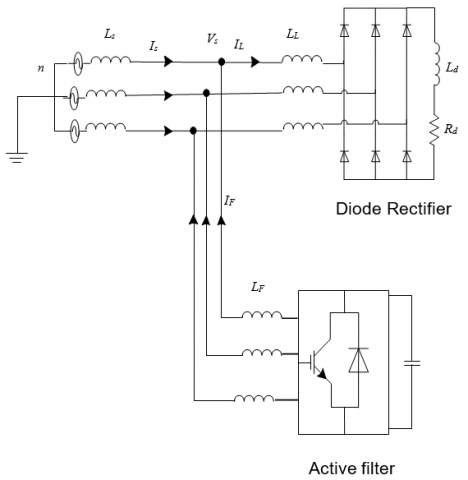
Fig. 1 presents the shunt active power filter topology based on a three-phase voltage source inverter, using IGBT switches, connected in parallel with the AC three-phase system through three inductors Lf. the capacitor C is used in the Dc side to smooth the Dc terminal voltage. The nonlinear load is a three-phase diode rectifier supplying a RL load. This load generates harmonic currents in the supply system. The proposed control strategy can be divided into two parts. The first part is the harmonic isolator (reference current generation). It consists in generating the harmonic current references and uses STF instead of HPF or LPF usually used in the classical instantaneous real and imaginary power theory, first proposed by H. Akagi (Abdusalam et al., 2008). This harmonic isolator will be implemented into a DSPACE system (ds1104 prototyping card) in the experimental study.
The second part is the current control of the power converter. This controller generates the suited switching pattern to drive the IGBTS of the inverter by using a modulated hysteresis current controller. In the experimental study, this controller is implemented into an analog card.
Figure 1. Power system configuration
Fig. 2 presents the schematic diagram of the three-phase active power filter and the associated control strategy for harmonic mitigation. The filter is connected in parallel with the mains. The non-linear load is a three-phase diode rectifier feeding a RL load. As mentioned above, the control method is divided into two parts. The first one consists in the harmonic isolator implemented into a DSPACE DS1104 development board. The second part is the analog hysteresis current controller, developed in our laboratory.
Figure 2. Experimental system
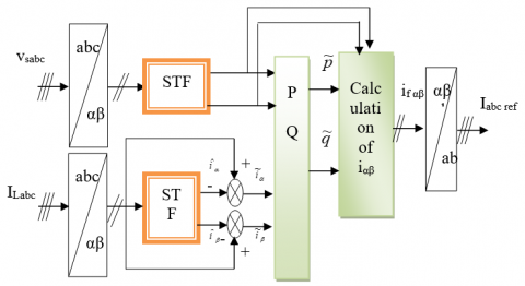
The identification method chosen effect the quality of the compensation of current harmonics. Many theories of instantaneous power exist in scientific literature the extension of the reactive power to non-sinusoidal waveforms is now a subject of controversy. Many new theories have been proposed. Akagi (Beaulieu & Ouhrouche, 2007). proposed a theory based on instantaneous values in three-phase power systems with or without neutral wire, and is valid for steady-state or transitory operations, as well as for generic voltage and current waveforms called as Instantaneous Power Theory or Active-Reactive (p-q) Theory which consists of an algebraic transformation (Clarke Transformation) of the three-phase voltages in the a-b-c coordinates to the α-β coordinates, followed by the calculation of the p-q theory instantaneous power components by eliminating the DC component of the instantaneous active power (corresponding to the fundamental component of load current) using a selective Filter STF, so the harmonic components can be identified. Figure 3 shows the modified scheme for the identification of reference currents during simultaneous compensation of harmonic currents and reactive power using the method of instantaneous power by using STF.
Figure 3. The method of instantaneous active and reactive power
This method is based on measuring the instantaneous three-phase variables present on the grid with or without zero-sequence components. This method is valid both in steady-state phase. In this control algorithm (Figure 2), measurements of voltages and currents expressed as a three phase (abc) are converted to two-phase system (α-β) is equivalent to using the transform from Concordia leaving the power invariant:
(1)
(2)
The power is composed of three parts, In the presence of harmonics: reactive (Q) active(P) and deformed (D) as shown by the following equation:
(3)
The instantaneous active power, denoted P(t) is defined by the following equation:
(4)
In the stationary reference can be written:
(5)
Can be written, the instantaneous imaginary power as follows:
(6)
Q power meaning than the usual reactive power. In fact, unlike the reactive power, which considers only the fundamental frequency, the imaginary power takes into account all the harmonic components of voltage and current that is why it is given a different name (imaginary power) as a unit with the volt-ampere imaginary (VAI). The part of the relations (5) and (6), we can establish the following matrix:
(7)
with:  Continuous power related to the fundamental component of active power and voltage,
  Continuous power related to the fundamental component of reactive current and tension,
  and
and  Powers of alternatives related to the sum of the components of disruptive current and voltage.
By inverting the relation (7), we can recalculate the currents in the coordinate α β as shown in the following equation
(8)
Considering equations (8) and (9), we can separate the current bench mark in the three components, active and reactive at the fundamental frequency and harmonics.
Finally, it is easy to obtain the reference currents along the axes abc by the inverse transformation of Concordia
(9)
(10)
To obtain a satisfactory extraction, the dynamic mode is slow. In general, cut-off frequency is selected enough low, between 5 Hz and 35 Hz, which generates then an instability of the active filter of power during fast variations of the load.
In the contrary case, if more raised cut-off frequency is chosen, precision determination of the alternate component is altered and can prove to be insufficient.
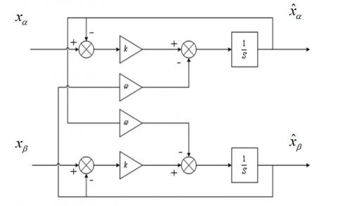
The self-tuning filter is the most important part of this control which allows to make insensible the PLL to the disturbances and filtering correctly the currents in α-β axis. Hong-Scok Song (Abdelmadjid et al., 2006) had presented in his PhD work how recovered the equivalent transfer function of the integration expressed by the block diagram of the STF tuned at the pulsation ωc is shown in the figure 5. The transfer function of this filter is:
According to the α-β axes, the expressions linking the components FMV output xαβ to input xαβ components are:
(11)
We obtain the following block diagram for STF
Figure 4. Self-tuning filter
In the stationary reference the dynamic equations of the active filter are given by:
$\left\{ \begin{array} { l } { \frac { d V _ { d c } } { d t } = \frac { p _ { d c } ^ { * } } { C _ { d c } V _ { d c } } } \\ { \frac { d i _ { j a } } { d t } = - \frac { R _ { f } } { L _ { f } } i _ { f a } + \frac { V _ { j a } - V _ { s a } } { L _ { f } } } \\ { \frac { d i _ { f \beta } } { d t } = - \frac { R _ { f } } { L _ { f } } i _ { f a } + \frac { V _ { f \beta } - V _ { s \beta } } { L _ { f } } } \end{array} \right.$ (12)
We have three outputs to regulate in this control strategy.
I- Subsystem 1
The equation of this subsystem is:
$\frac { d V _ { d c } } { d t } = \frac { p _ { d c } ^ { * } } { C _ { d c } V _ { d c } }$ (13)
The first sub-system of order 1, is characterized by its state, x=Vdc and its control: u=Pdc We can write the equation as follows:
$\dot { x } = f ( x ) + g ( x ) u$ (14)
$f ( x ) = 0 \quad$ and $g ( x ) = \frac { 1 } { C _ { d c } V _ { d c } }$
The voltage regulation Vdc is provided by the subsystem1. To achieve this object requires we must choose y=Vdc as output, then, we seek its relative degree.
(15)
Its derivative is given by:
(16)
And as Lie derivatives, we write:
(17)
With:
It follows that:
(18)
The law of order is expressed by:
(19)
(20)
(21)
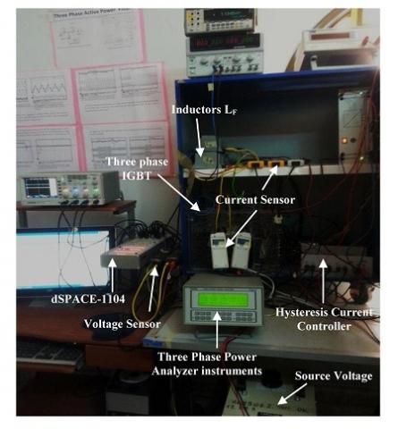
Figure 5. The photograph of the shunt APF prototype
(22)
The second sub-system of order 2, is characterized by its vector state
Alpha and beta vector control isWe can write the system of equations (22) under the form:
when:(23)
Now we will apply the state feedback control on models (22) and (23).
The complete active filter system is composed mainly of a three-phase source, a nonlinear load, a hysteresis current and a Non linear controller. We study the robustness of the non linear using experimental results for different operating modes. The test bench used for the experiment is presented in Fig. 5. The input step-down transformer (10.60KVA) is connected to the mains (380 V line to line) and delivers a lumped voltage of 220 V. The three-phase parallel active filter is achieved with a voltage source inverter. This VSI contains a three-phase IGBT 1200V, 50A (SKM 50 GB 123D). To ensure the dead time of control signals and the insulation, developed cards based on the IXDP630 component and specialized circuits (SKHI 22) are used.
The performances of non linear control of the DC bus voltage of three phase shunt active power filter extensive experimentation for various operating conditions and parameters variation.
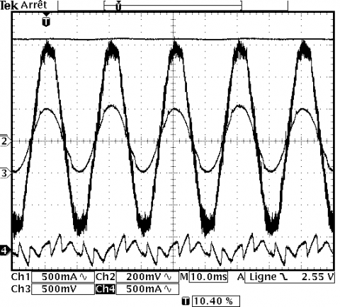
Figure 6. Experimental results: filter current iF (A), source current iS (A), source voltage Vs (V) and DC voltage Vdc (V). Ch3 and Ch4 scale: 5 A/div; Ch2 scale: 100 V/div; Ch1 scale: 80 V/div; Time scale: 10 ms/div.
First experimentation is done on fixed load, we observe that the DC-voltage is regulated well around the reference V*dc = 420 V. The mains current has a sinusoidal form and in phase with supply voltage (see Fig 6.), which minimizes the reactive power consumed by the inverter. It is confirmed for the two controllers in permanent response.
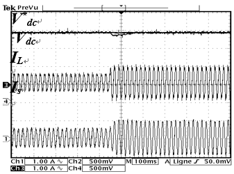
Second, to prove the dynamical response of the controllers at a transient condition, the DC side resistance is changed from RL to RL/2. It can be seen that the voltage controlled by the non linear at Fig.7 joined quickly his reference
Figure 7. Experimental results with load changed: Dc voltage and reference, Load current, Source current
Finally, two tests have been performed to confirm the effectiveness of the control of DC voltage using a nonlinear controller, First, we fixed the reference voltage at the value V*dc= 450V and the filter is switched; Figure. 8 show, the results of the DC voltage link, after a transient response due to the charging capacitor (the capacitor has been charged initially at 210V), that the DC-voltage is regulated well around the reference V*dc= 450 V.
Figure 8. Experimental results with feedback linearisation control of Dc voltage and reference voltage
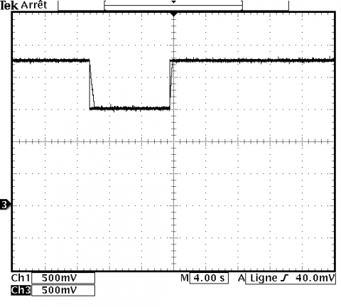
Second, a double change of the reference is shown 450-300 and 450V. It can be noted that, the DC voltage regulated by the non linear controller follows its reference, there is no overshoot and the settling time is very small (see Fig. 9).
Figure 9. Experimental APF results with Feedback linearized: DC voltage Vdc (V) and DC reference voltage V*dc (V), Ch3 and Ch4 scale: 100 V/div, Time scale: 2s/div
(a)
(b)
Figure 10. Grid current and its spectrum (a) before filtering (b) after filtering
Fig. 10 show the grid current, mainly affected by the low order harmonics (5th, 7th,11th), induced by the non-linear load; and as result, the THD factor is relatively high (23.6%). After compiling the APF, the grid current becomes quasi-sinusoidal, and no significant low order is noticed. Consequently, the total distortion factor (THD) is about 3.85%, meaning compliance with IEEE519-1992 norm.
The main goal of this article presented is articulated basically on two ideas, we have shown the effectiveness of the shunt active power filtering especially with the application of Non-linear control. After compensation The THD of the source voltage and the source current is well below 5%, the IEEE-519 standard imposes the harmonics limit. Further studies the power factor was corrected (power supply current and voltage became in phase). The control of the active power filter was divided into two parts, the first one realized by the DSpace system to generate the reference currents and the second one an analog card, implementing a hysteresis current controller. the proposed modified version of the p-q theory instead of classical extraction filters (low pass filters or high pass and) have been introduced by STFs, for both grid load currents and voltages. The use of this filter experimentally leads to satisfactory performances since it extracts the harmonic currents at high performances. Several tests have been performed in order to prove the efficiency of the controller. The experimental results presented in this article show that the method of feedback remarkably improves the operation of the active power filter in terms of the THD.
The experimental test bench parameters are:
|
Parameters Source |
Voltage (Vm)=120 V Frequency (f) =50Hz Resistance (RS)=0.42 Ω Inductance (LS)=2.3 mH |
|
Parameters load |
Resistance (Rl)=45 Ω Inductance (Ll) =1.3 mH |
|
Parameters filter |
DC link capacitor C=1100 μF DC link voltage V*dC=420v Inductance (LC)=0.8 mH Hysteresis band Δi=0.2 A |
Abdelmadjid C., Jean-Paul G. F. K., Laurent R. (2006). IP controlled three-phase shunt active power filter for power improvement quality. IEEE Industrial Electronics, IECON 2006. https://doi.org/10.1109/IECON.2006.348043
Abdusalam M., Poure P., Saadate S. (2008). Study and experimental validation of harmonic isolation based on high selectivity filter for three-phase active filter. In: IEEE International Symposium on Industrial Electronics, pp. 166-71. https://doi.org/10.1109/ISIE.2008.4676991
Afonso J. L., Couto C, Martins J. S. (2000). Active filters with control based on the p-q theory. IEEE Industrial Electronics Society Newsletter, Vol. 47, No. 3.
AitChihab A., Ouadi H., Giri F. (2014). Adaptive nonlinear control of three-phase shunt active power filters: power factor correction and dc bus voltage regulation. J Theor Appl Inf Tech nol 2014, Vol. 62, No. 1, pp. 27-37.
Beaulieu S., Ouhrouche M. (2007). Real-time modelling and simulation of an active power filter l ASTED International Conference on Power and Energy Systems PES 2007. Clearwater, Florida, U.S.A.
Ghamri A., TBenchouia M., Golea A. (2012). Sliding-mode control based three-phase shunt active power filter: Simulation and experimentation. Electric Power Components and Systems Journal, Vol. 40, No. 4, pp. 383-398.
Hasan K., Osman K. (2007). Globally stable control of three-phase three wire shunt active power filters. Electrical Engineering, Vol. 89, No.5, pp. 411-418. https://doi.org/10.1007/s00202-006-0012-8
Leszek S., Zarnecki C. (2006). Instantaneous reactive power p–q theory and power properties of three-phase systems. IEEE Transactions on Power Delivery, Vol. 21, No. 1, pp. 362–367. https://doi.org/10.1109/TPWRD.2005.852348
Lorenzo M., Fabio R., Andrea T. (2007). Robust nonlinear control of shunt active filters for harmonic current compensation. Automatica, Vol. 43, pp. 252–263. https://doi.org/10.1016/j.automatica.2006.08.021
Mohamed A., Philippe P., Shahrokh S. (2008). Control of hybrid active filter without phase locked loop in the feedback and feedforward loops ISIE. IEEE International Symposium on Industrial Electronics, Cambridge, UK.
Nadhir M., Ahmed O., Djaffar O. A. (2014). Direct power control of shunt active filter using high selectivity filter (HSF) under distorted or unbalanced conditions. Electric Power Systems Research, Vol. 108, pp. 113–123.
Sabir O., Achour B., Jean-Paul G. (2017). Simulation and real time implementation of predictive direct power control for three phase shunt active power filter. Simulation Modelling Practice and Theory, Vol. 78, pp. 1-17. https://doi.org/10.1016/j.simpat.2017.08.003
Saetieo S., Devaraj R., Torrey D. A. (1995). The design and implementation of a three phase active power filter based on sliding mode control. IEEE Transactions Industry Appl., Vol. 31, No. 5, pp. 993-99. https://doi.org/10.1109/28.464511
Singh B. N., Singh B., Chandra A., Al-Haddad K. (2000). Digital implementation of fuzzy control algorithm for shunt active filter. European Transactions on Electrical Power, Vol. 10, No. 6, pp. 369-375. https://doi.org/10.1002/etep.4450100606