OPEN ACCESS
In this paper, a second order sliding mode control for an induction motor is designed and implemented using a new technique of stability analysis. This approach guarantees the same robustness and dynamic performance of traditional first-order sliding mode control (SMC) algorithms, and at the same time, attenuates the chattering phenomenon, which is the main drawback in the actual implementation of this technique. The magnitude of the rotor flux of the induction motor is determined by the output of the closed-loop rotor flux observer based on twisting algorithm control theory. A set of experimental results are presented in order to validate the effectiveness of the proposed technique and to show the performance of 2-sliding mode control for an induction motor drive system.
induction motor control, second order sliding mode, twisting algorithm, sliding mode observer, robust control
Induction motor is one of the most popular AC motors and many control approaches has been applied to it due to industrial requirement and recent advances in electronic and microprocessor technology. However, the dynamic characteristics of the induction motor drive are complex, highly nonlinear and coupled. In addition, the drive control is sensitive to machine parameter variations and load disturbances.
The variable structure control strategy using the sliding mode has received much attention in recent years for controlling electric drives (Beltran 2012; Fu & Xie, 2005; Perruquetti & Barbot, 2002; Shyu & Shieh, 1996; Utkin et al., 1999; Utkin, 1993). The key objective of this technique is to force the system trajectory to occur on a prescribed manifold in the state space, known as the sliding surface. The primary characteristic of standard SMC is that the feedback signal is discontinuous. The most significant property of a SMC concerns its robustness, fast dynamic response and insensitivity to parameter variations (Utkin, 1993; Fu & Xie, 2005; Shyu & Shieh, 1996; Inanc, 2002). However, the standard sliding mode control suffers from the chattering phenomenon. To overcome this drawback, many methods have been proposed to reduce this phenomenon such as the saturation function, low pass filter, boundary layer and observer-based solutions (Park & Kim, 1991; Bartolini et al., 2000).
A research activity has been carried out in recent years, aimed at finding a continuous control action and guaranteeing the attainment of the same control objective of the standard SMC. A novel class of SMC algorithm, called the second-order sliding mode control (2-SMC) algorithm, has been proposed (Bartolini et al., 1998; Bartolini et al., 2003; Floquet et al., 2000). This approach allows for finite-time convergence to zero of not only the sliding manifold but its derivative too. The synthesis of the observers for the induction machine is a problem largely developed in the literature. Indeed, the control laws require, in most of the time, the flux information which is not a variable measured on this type of system (Belhadj et al., 2006). So, in order to obtaining an estimate, various methods were considered A new generation of observers based on the second-order sliding-mode algorithms has been recently developed, in particular twisting and super twisting (Bartolini et al., 1998; Floquet et al., 2000; Davila et al., 2005). The twisting algorithm provides the finite time convergence and robustness in spite of the presence of external disturbances and parameter variations.
The aim of this paper, is to develop a novel second order sliding mode approach for the stability analysis. We use this approach to control the speed and flux of an induction motor. An improvement of this method is verified by a practical implementation. The paper, also proposes a second-order sliding mode observer for rotor flux and current estimation using twisting algorithm. The convergence of the observed flux is guaranteed by the convergence of the observed currents. Experimental results present the good performance of the proposed method.
The two phase’s equivalent model for an induction motor in the stationary reference frame of Park are given by (Floquet et al., 2000; Inanc, 2002; Shyu & Shieh, 1996):
$\dot{x}=f(x)+g(x){{u}_{s}}$ (1)
$f ( x ) = \left[ \begin{array} { c } { f _ { 1 } ( x ) } \\ { f _ { 2 } ( x ) } \\ { f _ { 3 } ( x ) } \\ { f _ { 4 } ( x ) } \\ { f _ { 5 } ( x ) } \end{array} \right] = \left( \begin{array} { c } { - \delta i _ { s \alpha } + \alpha \beta \phi _ { r \alpha } + p \beta \omega \phi _ { r \beta } } \\ { - \delta i _ { s \beta } - p \beta \omega \phi _ { r \alpha } + \alpha \beta \phi _ { r \beta } } \\ { \alpha M i _ { s \alpha } - \alpha \phi _ { r \alpha } - p \omega \phi _ { r \beta } } \\ { \alpha M i _ { s \beta } + p \omega \phi _ { r \alpha } - \alpha \phi _ { r \beta } } \\ { \mu \left( \phi _ { r \alpha } i _ { s \beta } + \phi _ { r \beta } i _ { s \alpha } \right) - \frac { T _ { L } } { J } } \end{array} \right)$
$g ( x ) = \left[ \begin{array} { l l l l } { b } & { 0 } & { 0 } & { 0 } \\ { 0 } & { b } & { 0 } & { 0 } \end{array} \right] ^ { T } = \left[ \begin{array} { c c c c } { g _ { 1 } ( x ) } & { 0 } & { 0 } & { 0 } \\ { 0 } & { g _ { 2 } ( x ) } & { 0 } & { 0 } \end{array} \right] ^ { T }$, $x={{[{{i}_{s\alpha }}\,\,{{i}_{s\beta }}\,\,{{\varphi }_{r\alpha }}\,\,{{\varphi }_{r\beta }}\text{ }\omega ]}^{T}}$
f(x) is a vector of dimension n=5 the coefficients of which are non-linear functions.
For simplicity, we define the following variables:
$\alpha =\frac{1}{{{T}_{r}}}=\frac{{{R}_{r}}}{{{L}_{r}}},\text{ }\sigma =1-\frac{{{M}^{2}}}{{{L}_{s}}{{L}_{r}}}\text{, }\beta =\frac{\text{M}}{\sigma \text{ }{{L}_{s}}{{L}_{r}}},b=\frac{1}{\sigma {{L}_{s}}}\text{, }\mu =\frac{pM}{J {{L}_{r}}},\text{ }\delta =\frac{{{M}^{2}}{{R}_{r}}}{\sigma {{L}_{s}}L_{r}^{2}}+\frac{{{R}_{s}}}{\sigma {{L}_{s}}}$
where фrα, фrβ are the rotor flux dynamics and isα, isβ are the stator currents. The control vector is defined by us=[usα, usβ]T and TL is the load torque, ω is the mechanical frequency of the electrical rotor speed, σ is total leakage factor. Rs and Rr denote stator and rotor resistance, Ls and Lr are stator and rotor self-inductance, M is mutual inductance, p is the number of pole pairs and J is the moment of inertia.
The objective of the proposed control scheme is to control independently the rotor speed and the square of the rotor flux and in the same time we attenuate of the chattering phenomenon.
3.1. Problem formulation
Let e1 and e2 the speed and flux error between the reference and the actual induction motor model with:
$\varphi = \phi _ { r \alpha } ^ { 2 } + \phi _ { r \beta } ^ { 2 }$, $e = \left[ \begin{array} { l } { e _ { 1 } } \\ { e _ { 2 } } \end{array} \right] = \left[ \begin{array} { l } { \omega _ { r e f } - \omega } \\ { \varphi _ { r e f } - \varphi } \end{array} \right]$ (2)
where ωref and ref are the desired reference signals.
Consider the sliding surface defined by (Utkin et al., 1999):
$S=q\int{e+e}$ (3)
witch: $q=\left[ \begin{matrix} {{q}_{\omega }} & 0 \\ 0 & {{q}_{\phi }} \\\end{matrix} \right]$, $S=\left[ \begin{matrix} {{s}_{\omega }} \\ {{s}_{\phi }} \\\end{matrix} \right]=\left[ \begin{matrix} {{e}_{1}}+{{q}_{\omega }}\int{{{e}_{1}}} \\ {{e}_{2}}+{{q}_{\phi }}\int{{{e}_{2}}} \\\end{matrix} \right]$,
qω, qφ positive constant.
Note that the choice of the sliding surface S = 0 has been made to ensure an exponential convergence of ω and φ to their references where the system evolves on the sliding surface.
The second derivative of the sliding surface S is:
$\ddot{S}=q\dot{e}+\ddot{e}$ (4)
The error dynamics are given by:
$\dot { e } _ { 1 } = \dot { \omega } _ { r e f } - \mu \left( \phi _ { r \alpha } i _ { s \beta } - \phi _ { r \beta } i _ { s \alpha } \right) + \frac { T _ { L } } { J }$
$\ddot { e } _ { 1 } = h _ { 1 } ( x ) + D _ { 1 } ( x ) u _ { s }$ (5)
$\begin{align} & {{{\dot{e}}}_{2}}={{{\dot{\phi }}}_{ref}}+2\alpha \phi -2\alpha M({{\varphi }_{r\alpha }}{{i}_{s\alpha }}+{{\varphi }_{r\beta }}{{i}_{s\beta }}) \\ & {{{\ddot{e}}}_{2}}={{h}_{2}}(x)+{{D}_{2}}(x){{u}_{s}} \\ \end{align}$ (6)
$\begin{align} & {{h}_{1}}(x)={{{\ddot{\omega }}}_{ref}}+pu\omega ({{\varphi }_{r\alpha }}{{i}_{s\alpha }}+{{\varphi }_{r\beta }}{{i}_{s\beta }}) \\ & \text{ }+\mu (\delta +\alpha )({{\varphi }_{r\alpha }}{{i}_{s\beta }}-{{\varphi }_{r\beta }}{{i}_{s\alpha }})+pu\beta \omega \phi +\frac{{{{\dot{T}}}_{L}}}{J} \\ \end{align}$
$\begin{align} & {{h}_{2}}(x)={{{\ddot{\phi }}}_{ref}}+2M(\delta +3{{\alpha }^{2}})({{\varphi }_{r\alpha }}{{i}_{s\alpha }}+{{\varphi }_{r\beta }}{{i}_{s\beta }})-2{{\alpha }^{2}}(2+M)\phi \\ & \text{ }-2pM\alpha \omega ({{\varphi }_{r\alpha }}{{i}_{s\beta }}-{{\varphi }_{r\beta }}{{i}_{s\alpha }})-2{{M}^{2}}{{\alpha }^{2}}(i_{s\alpha }^{2}+i_{s\beta }^{2}) \\ \end{align}$
${{D}_{1}}=[ub{{\varphi }_{_{r\beta }}}-ub{{\varphi }_{r\alpha }}]$, ${{D}_{2}}=[\begin{matrix} -2\alpha Mb{{\varphi }_{r\alpha }} & -2\alpha Mb{{\varphi }_{r\beta }}] \\\end{matrix}$
3.2. Lyapunov stability analysis for the proposed second order sliding mode control
To determine the control law that leads the sliding functions (3) to zero in finite time, we consider the dynamics of:
$\begin{align} & {{S}_{\omega }}+{{{\ddot{S}}}_{\omega }}={{H}_{1}}(x)+{{D}_{1}}(x){{u}_{s}} \\ & {{S}_{\phi }}+{{{\ddot{S}}}_{\phi }}={{H}_{2}}(x)+{{D}_{2}}(x){{u}_{s}} \\ \end{align}$
With
${{H}_{1}}(x)=q\int{{{e}_{1}}dt+{{e}_{1}}}+q{{\dot{e}}_{1}}+{{q}_{\omega }}({{\dot{\omega }}_{ref}}-{{f}_{5}})+{{h}_{1}}(x)$,${{H}_{2}}(x)=q\int{{{e}_{2}}dt+{{e}_{2}}+{{q}_{\phi }}{{{\dot{e}}}_{2}}+{{h}_{2}}(x)}$
We can write:
$S+\ddot{S}=H(x)+D(x){{u}_{s}}$ (7)
The control law for the second order sliding mode control (SOSMC) of the system is described as
${{u}_{s}}=-{{D}^{-1}}(x)[H(x)+\lambda sng(\dot{S})]$ (8)
D is invertible and $\lambda =\left[ \begin{matrix} {{\lambda }_{\omega }} & 0 \\ 0 & {{\lambda }_{\phi }} \\\end{matrix} \right],\,\,\text{ }{{\lambda }_{\omega }},\,{{\lambda }_{\phi }}>0,$
We can verify the stability of the sliding surface by using the new positive Lyapunov function as fellow:
$V=\frac{1}{2}({{S}^{2}}+{{\dot{S}}^{2}})$ (9)
The derivative of V is:
$\dot{V}=(\dot{S}\text{ }S+\dot{S}\text{ }\ddot{S})={{\dot{S}}^{T}}(S+\ddot{S})$ (10)
The expression (7) becomes:
$S+\ddot{S}=H(x)+D(x)\text{ }{{u}_{s}}=-\lambda \text{ }sng(\dot{S})$ (11)
The derivative of V (10) becomes:
$\dot{V}=-\lambda \text{ }{{\dot{S}}^{T}}sng(\dot{S})$ (12)
Then
$\dot{V}=-{{\lambda }_{\omega }}\left| {{{\dot{S}}}_{1}} \right|-{{\lambda }_{\varphi }}\left| {{{\dot{S}}}_{2}} \right|\le 0$ (13)
With the developed nonlinear sliding-mode controller (8) the reaching Lyapunov function condition is satisfied, and the controlled system will be stabilized. The Lyapunov function V tends to 0 and therefore the surfaces s and s tend to zero and their derivative, hence the existence of second order sliding mode.
Remark: From the above control law of equation (8), it can be seen that the implementation of these algorithms requires the load torque and rotor flux estimations since stator currents, stator voltages and speed rotor are available by measures. In the next section, we are interested by a robust estimation of rotor flux. The estimated load torque can be easily obtained by using the mechanical equation of the motor model with estimated rotor fluxes and measured stator currents.
The four first equations of system (1) can be written as follows:
$\begin{align} & \frac{d{{i}_{s}}}{dt}=-\delta .I.{{i}_{s}}+\beta .A.{{\varphi }_{r}}+b.I.{{u}_{s}} \\ & \frac{d{{\varphi }_{r}}}{dt}=\alpha .M.I.{{i}_{s}}-A.{{\varphi }_{r}} \\ \end{align}$ (14)
${{i}_{s}}={{\left[ \begin{matrix} {{i}_{s\alpha }} & {{i}_{s\beta }} \\\end{matrix} \right]}^{T}}$,${{\varphi }_{r}}={{\left[ \begin{matrix} {{\varphi }_{r\alpha }} & {{\varphi }_{r\beta }} \\\end{matrix} \right]}^{T}}$,
$A=\left[ \begin{matrix} \alpha & p\omega \\ -p\omega & \alpha \\\end{matrix} \right],\text{ }I=\left[ \begin{matrix} 1 & 0 \\ 0 & 1 \\\end{matrix} \right]$
The corresponding sliding mode observer, for the system of (14), can be written as a replica of the system with an additional non-linear auxiliary input term (Γ) as follows:
$\begin{align} & \frac{d{{{\overset{\scriptscriptstyle\frown}{i}}}_{s}}}{dt}=-\delta .I.{{i}_{s}}+\beta .A{{{\overset{\scriptscriptstyle\frown}{\varphi }}}_{r}}+b.I.{{u}_{s}} \\ & \frac{d{{{\overset{\scriptscriptstyle\frown}{\varphi }}}_{r}}}{dt}=\alpha .M.I.{{{\overset{\scriptscriptstyle\frown}{i}}}_{s}}-A{{{\overset{\scriptscriptstyle\frown}{\varphi }}}_{r}}+\Gamma \\ \end{align}$ (15)
${{\overset{\scriptscriptstyle\frown}{i}}_{s}}={{\left[ \begin{matrix} {{{\overset{\scriptscriptstyle\frown}{i}}}_{s\alpha }} & {{{\overset{\scriptscriptstyle\frown}{i}}}_{s\beta }} \\\end{matrix} \right]}^{T}}$,${{\overset{\scriptscriptstyle\frown}{\varphi }}_{r}}={{\left[ \begin{matrix} {{{\overset{\scriptscriptstyle\frown}{\varphi }}}_{r\alpha }} & {{{\overset{\scriptscriptstyle\frown}{\varphi }}}_{r\beta }} \\\end{matrix} \right]}^{T}}$are the estimated stator-current and the rotor flux components in the stationary reference frame.
$\Gamma ({{z}_{1}})={{\left[ \begin{matrix} {{\Gamma }_{1}} & {{\Gamma }_{2}} \\\end{matrix} \right]}^{T}}$ is the observer matrix gains to be designed.
The estimate errors are:
$\begin{align} & {{z}_{1}}={{{\overset{\scriptscriptstyle\frown}{i}}}_{s}}-{{i}_{s}} \\ & {{z}_{2}}={{{\overset{\scriptscriptstyle\frown}{\varphi }}}_{r}}-{{{\overset{\scriptscriptstyle\frown}{\varphi }}}_{r}} \\ \end{align}$ (16)
The observation error dynamics is obtained from equation (15) and (16)
$\begin{align} & {{{\dot{z}}}_{1}}=\beta .A.{{z}_{2}} \\ & {{{\dot{z}}}_{2}}=\alpha .MI.{{z}_{1}}-A.{{z}_{2}}+\Gamma \\ \end{align}$ (17)
The sliding surface is defined as follows (Davila et al., 2005)
$s=\frac{1}{\beta }{{A}^{-1}}{{z}_{1}}$ (18)
The derivative of the sliding surface is:
$\dot{s}=\frac{1}{\beta }{{A}^{-1}}{{\dot{z}}_{1}}+\frac{d({{A}^{-1}})}{dt}{{z}_{1}}={{z}_{2}}$ (19)
The dynamics of ω is supposed to be constant compared to the dynamics of the currents and flux, we can then consider$\frac{d({{A}^{-1}})}{dt}=0$.
$\begin{align} & \dot{s}={{z}_{2}} \\ & \ddot{s}={{{\dot{z}}}_{2}}=\alpha .M.I.{{z}_{1}}-A.{{z}_{2}}+\Gamma \\ \end{align}$ (20)
With this form we can apply the following control laws, called the twisting algorithm (Floquet et al., 2000):
$\Gamma =\left\{ \begin{align} & {{\lambda }_{m}}sng(s)\text{ s\dot{s}}\le \text{0} \\ & {{\lambda }_{M}}sng(s)\text{ s\dot{s}}>\text{ 0} \\ \end{align} \right.$ (21)
The sufficient conditions for finite time convergence are:
$\begin{align} & {{\lambda }_{m}}>{{\left| \alpha MI{{z}_{1}}-A{{z}_{2}} \right|}_{\max }} \\ & {{\lambda }_{M}}>{{\lambda }_{m}}+2{{\left| \alpha MI{{z}_{1}}-A{{z}_{2}} \right|}_{\max }} \\ \end{align}$ (22)
The system evolves featuring a second order sliding mode and the trajectories of state reached the surface after a finite time, $s=\dot{s}=\text{ }0$.
The parameters of the IM used are listed in Table.1. The load torque (TL=7.3 N.m) is applied during the whole simulation. In closed loop during the motor operating, it is assumed that all parameters of induction motor will be considered as constant except rotor resistance Rr will be treated as uncertain parameter with Rrn as its nominal value.
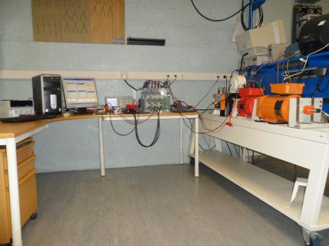
The experimental setup of the proposed control system is shown in Figure.8. It consists of a Dspace DS1104 controller board with TMS320F240 slave processor, ADC interface board CP1104. A three-phase VSI inverter is connected to DC bus voltage, with the switching frequency 10 kHz.The control program is written in Matlab/Simulink real time interface with sampling time of 10-4s.
The motor is required to track the reference speed and rotor flux magnitude. The cut-off frequency of the low pass filter for the measured speed is chosen as 5Hz. The reference flux is set to 0.7Wb. The parameters of the gain control in experiments are: qω=2000, qj=3000, λω=20, λj=50.
To be able to prove the performance of the proposed sliding mode approach and the flux observer for the different speed conditions, several tests have been performed and the results given in following figures.
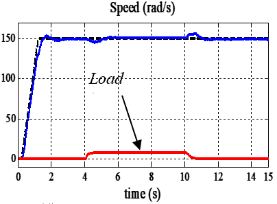
The following test consists of applying external load disturbances at [4s 10s], see Figure.1. The reference trajectory of speed is in a form given by Figure (1.b) varying from 0 to 150 rad/s. The objective is to follows the speed and rotor flux references in spite of disturbances in load torque. The motor is started without load, after, a 73% rated load is applied at t=4s and suddenly removed at t=10s under normal operating conditions.
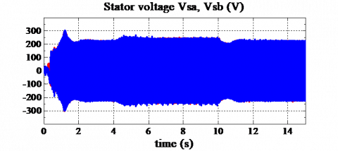
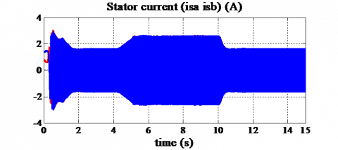
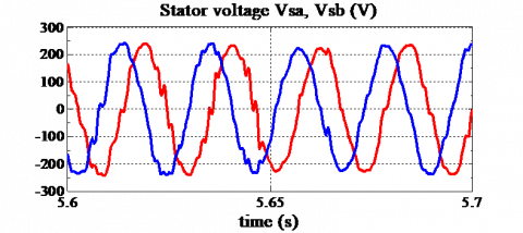
We can see in Figure 2 (a and c) the speed and the observed rotor flux responses for no load. It can be seen that a very small steady state error (0.705 Wb in the rotor flux amplitude) and a speed overshoot which are still very small values. The tracking is quite maintained and the reject of the load torque is achieved after a short convergence time (0.6s). The sinusoidal stator current isα, isβ and voltage waveforms for new control inputs usα, usβ for the 2-SMC system are shown in Figure 2 (d and e). It can be seen that the chattering is negligible.
Figure 1. Load torque TL
(a) Load torque TL
(b) Rotor speed
(c) reference and observed rotor flux,
(d) zoom of rotor speed shows the reject of disturbance, stator voltage
(e) Stator current (isa,isb)
Figure 2. Experimental dynamic responses of rotor speed under load torque TL=7.3 Nm
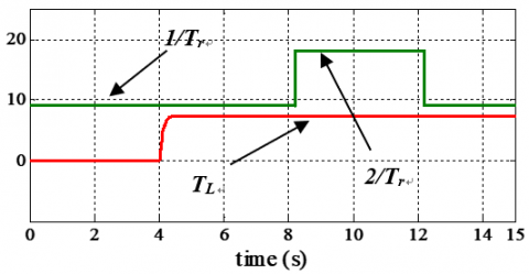
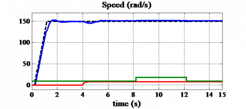
The results reported in Figure 3 illustrate the performance of the proposed control under increasing in inverse of rotor time constant 1/Tr with presence of load torque Figure 3a. The motor is started with its nominal rotor time constant, then, 1/Tr is suddenly set to +100% variation at [8s 12s]. It can be seen from Figure 3 (b and c) a good speed regulation is obtained with negligible steady state error.
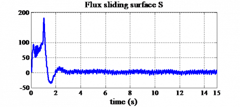
It is seen from Figure 4 the convergence to the second sliding mode surface $S = \dot { S } = 0$ and the convergence of the flux sliding manifold Sφ to zero.
(a) Load torque and 1/Tr variation
(b) Rotor speed
(c) zoom of rotor speed.
Figure 3. Experimental dynamic responses of rotor speed with TL=7.3Nm and 100% 1/Tr variation
Figure 4. Experimental results: Flux sliding surface Sj and the trajectory of the flux sliding manifold on the plane ($S , \dot { S } $)
(a)
(b)
(c)
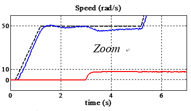
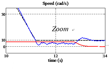
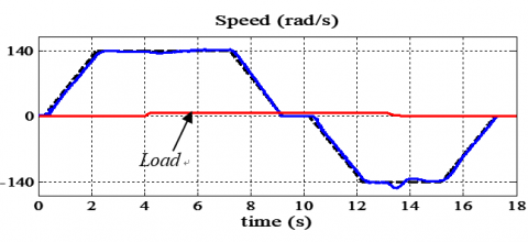
Figure 5. Experimental responses for speed variation under load torque 7.3 Nm
To test the speed tracking controller, we consider the speed tracking performances for a wide variation range of reference speed. In the first test, the induction motor is accelerated from the standstill to 50 rad/s, afterwards it is accelerated again to 140 rad/s and decelerated to low speed 10 rad/s. Figure 5 shows the good speed tracking and well reject of the load torque is achieved with acceptable steady state errors as shown in zoom of speed.
(a) Rotor speed
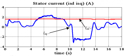
(b) Stator current
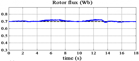
(c) Rotor flux observer
Figure 6. Experimental responses with speed variation under load torque 7.3 Nm
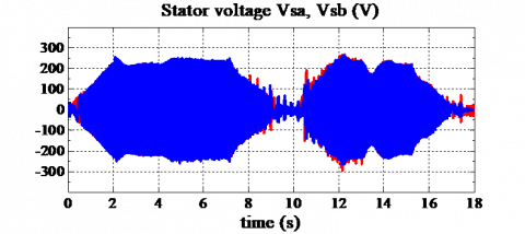
(a) Stator voltage
(b) Zoom of stator voltage
Figure 7. Experimental responses with speed variation under load torque 7.3 Nm
Figure 8. Experimental system consists of a 1.5 Kw induction motor, voltage source inverter and a digital signal processor DSP1104
In the second test, the reference speed is now changed to the trapezoidal form (140 rad/s), as shown in Figure 6a. A sudden load has been then applied at t=4s, the speed and rotor flux follow their references with steady state 141.5 rad/s, 0.73Wb respectively. Figure.6b shows the stator currents isd, isq in the synchronous reference frame of Park which prove that the decoupling is maintained. The control gives good quality results and the command voltages waveform usα, usβ in stationary reference frame (α, β) Figure 7.
Table 1. Induction motor parameters
|
Pn=1.5KW, Vn=220v, f= 50Hz |
|||
|
Rs |
5.72 Ω |
Ls |
0.462 H |
|
Rr |
4.2 Ω |
Lr |
0.462 H |
|
M |
0.4402 H |
J |
0.0049 Kg.m2 |
|
p |
2 |
F |
s/rad |
It is concluded from the experimental results, that this study has successfully demonstrated the design and implementation of new second order sliding mode control. The new Lyapunov stability analysis technique demonstrates the very good performance and stability, under rotor resistance variation, external load disturbances and speed tracking with a negligible chattering. Experiment results prove successfully the validity of the proposed approach.
Bartolini G., Damiano A., Gatto G., Marongiu I., Pisano A., Usai E. (2003). Robust speed and torque estimation in electrical drives by second order sliding modes. IEEE Trans. Control. System Technol., Vol. 11, pp. 84-90. https://doi.org/10.1109/TCST.2002.806441
Bartolini G., Ferrara A., Usai E. (1998). Chattering avoidance by second-order sliding mode control. IEEE Trans. on Automatic Control, Vol. 43, No. 2, pp. 241-246. https://doi.org/10.1109/9.661074
Bartolini G., Ferrara A., Usai E., Utkin V. I. (2000). On multi–input chattering–free second order sliding mode control. IEEE Trans. on Automatic Control, Vol. 45, No. 9, pp. 1711-1717. https://doi.org/10.1109/9.880629
Belhadj J., Sellami A., Benmabrouk W. (2006). Les observateurs à mode glissant pour le contrôle direct en couple d’une machine asynchrone. Intérêt et amélioration de la structure. European Journal of Electrical Engineering, Revue des Systèmes, Vol. 9, No. 2-3, pp. 209-233.
Beltran B., Benbouzid M.E.H., Ahmed-Ali T., Mangel H. (2012). Commande d’une éolienne à base de GADA par modes glissants d’ordre supérieur et observateur grand gain. European journal of Electrical Engineering, Revue des Systems, Vol. 15, No. 6, pp. 659-667.
Davila J., Fridman L., Levant A. (2005). Second order sliding mode observer for mechanical systems. IEEE Trans. on Automatic Control, Vol. 50, No. 11, pp. 1785-1789. https://doi.org/10.1109/TAC.2005.858636
Floquet T., Barbot J. P., Perruquetti W. (2000). Second order sliding mode control for induction motor. 39thIEEE Conf. on Decision and Control, Sydney, Australia. https://doi.org/10.1109/CDC.2000.912105
Fu T. J., Xie W. F. (2005). A novel sliding-mode control of induction motor using space vector modulation technique. ISA Transactions, Vol. 44, pp. 481-490. http://dx.doi.org/10.1016/S0019-0578(07)60055-X
Inanc N. (2002). A new sliding mode flux and current observer for direct field-oriented induction motor drives. Electric Power Systems Research. Elsevier Science, Vol 63, pp. 113-118. http://dx.doi.org/10.1016/S0378-7796(02)00084-6
Park M. H., Kim K. S. (1991). Chattering reduction in the position control of induction motor using the sliding mode. IEEE Trans on Power Electronics, Vol. 6 No. 3, pp. 317-325. http://dx.doi.org/10.1109/63.85898
Perruquetti W., Barbot J. P. (2002). Sliding mode control in engineering. Control. Engineering Series. Eds. Marcel Dekker.
Shyu K. K., Shieh H. J. (1996). A new switching surface sliding- mode speed control for induction motor drive systems. IEEE Trans. Power Electronics, Vol. 11, No. 4, pp. 660-667. http://dx.doi.org/10.1109/63.506132
Utkin V. I. (1993). Sliding mode control design principles and applications to electric drives. IEEE Trans on Industrial Electronics, Vol. 40, No. 1, pp. 23-36. http://dx.doi.org/10.1109/41.184818
Utkin V. I., Guldner J., Shi J. (1999). Sliding mode control in electromechanical systems. Eds. Taylor-Francis.