OPEN ACCESS
This paper puts forward a multi-sensor intelligent control system for bladeless fans, with the aim to realize automatic fan control and flexible adjustment of the blowing velocity. The system hardware includes a position detector, a distance detector, a fan speed governor and fan rotation angle controller circuits, and the system software encompasses a main program and proper device subroutines. The proposed system was verified through control experiments on a bladeless fan. The results show that the system adjusted the angle of the bladeless fan timely according to the changing human position, such that the fan was finally aligned with the human body. Moreover, the outlet velocity of the bladeless fan was sucessfully controlled according to the distance between human and fan. With the proposed system, the bladeless fan provided the user with constant blowing velocity and wind power. The research findings shed new light on the wind velocity adjustment and intelligent control of bladeless fans.
bladeless fan, distance detection, wind speed regulation.
As a new type, the bladeless fan can continuously supply natural cool breezes from an annular notch. As it features bladeless, energy conservation, environmental protection, and safety, it is widely applied in families where there are the elderly people and children (Wang et al., 2014). The bladeless fan currently available on the market, however, has some defects as follows: (1) The system fails to control whether to enable the blowing-in function according to the ambient temperature; (2) The air blowing speed is adjusted manually, and cannot be done in real time based on the distance between the human and the bladeless fan; (3) The mechanical reciprocating side-to-side swing in the blowing process cannot timely adjust the blowing angle depending on the change in the human body position (Li et al., 2014).
In allusion to the above defects, this paper proposes a design scheme of control system for intelligent bladeless fan with multi-sensors as the core, which uses pyroelectric sensor to detect the position of human body and changes the rotation angle of the bladeless fan by a controller circuit until the fan is aligned with the human body for blowing breezes; applies infrared distance measurement sensor to perform distance detection, thereby achieving intelligent adjustment on air flow speed. Here also describes the hardware circuit of the system, the design method of the software programs and the test results in detail.
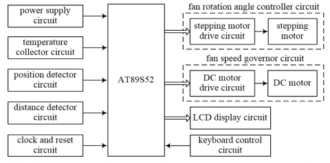
A block diagram of control system for intelligent bladeless fan based on multi-sensors is shown in Figure 1. The system consists of the circuits for multi-stage devices such as the power supply, temperature collector, position detector, distance detector, fan rotation angle controller, fan speed governor, liquid crystal display, and keyboard control.
Figure 1. Architecture of control system for intellectual bladeless fan
The working principle comes here as follows: First, the system detects the ambient temperature by the temperature collector, and continues to perform temperature acquisition until the ambient temperature is greater than the preset temperature value; the system then uses the position and the distance detector in the circuits to check whether there is anyone within the blowing scope as specified, if no, the system will change the rotation angle with the angle controller and then continue to detect until someone is found in the blowing scope; if this is the case, the system will control the speed of the DC motor by fan speed governor circuit based on the distance measured between the human and the bladeless fan, thus changing the blowing speed of circular notch to achieve the speed adjustment; the system can also use LCD to timely display the ambient temperature as captured, set the temperature and man-machine distance, as well to change the preset temperature by the keyboard control circuit (Gao and Yin, 2017).
3.1. Position detector circuit
The position detector circuit is mainly used to detect whether there is anyone within the current environment. Since the pyroelectric sensor HC-SR501 can measure the infrared signal emitted by the human body, and output the corresponding electrical signal in line with the detection conditions (Wang and Mo, 2016); the sensor's sensing distance can be continuously adjusted within 0 ~ 7m, and the sensing angle is a cone one less than 100° (Deng et al., 2016); The detection range is greater than that of the distance detector circuit, as required in the system design; This circuit, therefore, uses HC-SR501 to detect where the human body lies. The position detection circuit is shown in Figure 2.
Figure 2. Position detector circuit
In the figure, the pyroelectric sensor HC-SR501 is powered by a DC 5V power supply, and its output terminal OUT is connected to the base of an NPN transistor S9013 via a current limit resistor R1. The S9013 collector is coupled to the pin P3.2 of the Single Chip Microcomputer (SCM) AT89S52. RD and RT are the distance and delay regulator potentiometers, respectively, used to adjust the maximum sensing distance and delay time of the pyroelectric sensor; the maximum sensing distance of this circuit is set to 4m, and the delay time is set to 0.5s.
When it is checked there is someone within the environmental range, the OUT terminal of the HC-SR501 outputs a high level (3.3V) to supply the base of the transistor S9013, S9013 is breakover. The pin P3.2 of SCM is pulled to a low level. Conversely, when there is none in the environment, the terminal OUT of the HC-SR501 outputs a low level; the transistor S9013 is not breakover; the pin P3.2 of the SCM is input with a high level.
3.2. Distance detector circuit
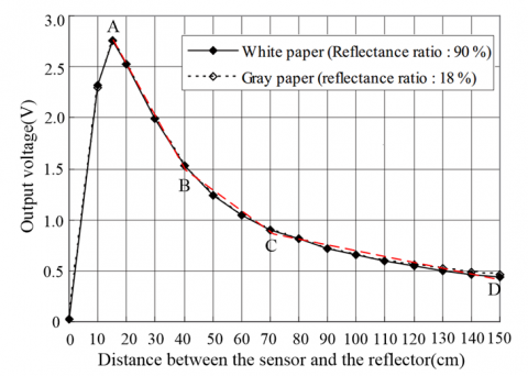
The distance detector circuit is used to detect what is the distance between the human and the bladeless fan. As Sharp's infrared distance measurement sensor GP2Y0A02YK0F is applied to this circuit design by virtue of its advantages such as high measurement accuracy, convenient data treatment, and strong anti-interference performance (Zhang and Zhang, 2015). The output characteristic curve of this sensor is shown in Figure 3.
Figure 3. Output characteristic curve of sensor GP2Y0A02YK0F
As shown in the figure, the output voltage is inversely proportional to and nonlinear correction with the distance between the sensor and the measured reflector. When the sensor's measurement distance is 15cm ~ 150cm, the corresponding output voltage is 2.8V ~ 0.4V; when the measurement distance is less than 15cm, the output voltage swoops from 2.8V to 0V. Since this measurement curve fluctuates greatly, the actual distance cannot be accurately measured, and the output characteristics should be evaded in the actual design. The specific practice is to move the sensor backward during installation to make sure it is exactly at the distance of 15 cm from the outer edge at the front end of bladeless fan (Huang and Li, 2013). To clarify the relationship between the output voltage and the measurement distance, a linear fitting algorithm (Wei et al., 2015; Gao et al., 2016; Yuan, 2014) is used to fit the three dotted lines AB, BC, and CD, as shown in the figure, with the original curve for output characteristics, and the I/O function relationship is obtained:
$Dist=\left\{\begin{array} {c c} {-19.2\times Volt+68.8,} & {1.5\le Volt \le 2.8} \\ {-50\times Volt+115,} & {0.9\le Volt \le 1.5} \\ {-160\times Volt+214,} & {0.4\le Volt \le 0.9} \end{array}\right.$ (1)
Where, Volt is the output voltage of the infrared distance measurement sensor, V; Dist is the distance between the sensor and the measured reflector, cm.
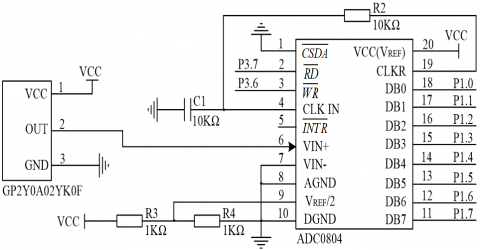
The distance detector circuit is shown in Figure 4. The system first uses the sensor GP2Y0A02YK0F to detect the distance between the human and the sensor during the operation, and the terminal OUT outputs the analog voltage corresponding to the measured distance; the analog voltage is then sent from the VIN terminal to the 8-bit A/D converter ADC0804 for the analog/digital conversion, and outputs the converted digital quantity from DB0-DB7 terminal to the SCM port P1; Finally, the detected distance is available between human and the bladeless fan. This circuit also starts A/D conversion, and read data determined by the control signals output at the terminal $\overline{WR}$, $\overline{RD}$ of ADC0804 from SCM pins P3.6 and P3.7 (Li et al., 2015).
Figure 4. Distance detector circuit
3.3. Fan speed governor circuit
The regulation of the bladeless fan blowing speed is achieved by this way that speed governor circuit control the speed of the DC motor thereby changing the blast velocity of the annular notch in the bladeless fan. The speed governor follows the principle that the "wind is weak for near people and strong for further people”, that is, when the person approaches to the fan, the fan blows out breezes, otherwise, it blasts strongly to let people feel a constant wind power.
The circuit design selects the WS-63ZYT108-R type DC motor with rated voltage 24V, the rated current 3.2A, the rated power 50W, the rated speed 4500r/min, and the rated torque 2520g.cm.
Figure 5. Fan speed governor circuit
Fan speed governor circuit is shown in Figure 5, where a pulse width modulation is used to control the speed of the DC motor, that is, SCM P2.5 pin outputs PWM of different duty cycle to control the average voltage of DC motor armature for speed regulation (Guo et al., 2016; Du et al., 2016). In the figure, in order to increase the drive current of the DC motor, two NMOS tubes IRF520 are connected in parallel to jointly control the working condition of the DC motor. The working process of the circuit is given as follows: When the pin P2.5 outputs a high level, the transistor S9013 is breakover to make the IRF520 gate voltage level high. Both IRF520s are breakover and the DC motor is powered; otherwise, when the pin P2.5 outputs a low level, S9013 interrupts, and both IRF520s are cut off. The DC motor does not work.
The system software mainly includes the main program and several subroutines for distance detector, speed governor, position detector, fan rotation angle controller, and temperature collector.
4.1. Distance detector subroutine
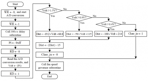
The distance detector subroutine is mainly used to control the distance detector to achieve the distance detection between the human and bladeless fan, A/D conversion and data treatment. The flow chart of the distance detector subroutine is shown in Figure 6. In the figure, the variables used are as follows: Dist is the distance variable between human and infrared distance measurement sensors, cm; Dist1 is the variable of the distance between the human and the outer edge at the front end of bladeless fan, cm; Chao_ju is the ultradistance flag bit, when Dist>150cm, flagged as 1, otherwise reset to zero.
The program process is given as follows: First, set the pin $\overline{WR}$ to the low level to start the A/D converser; secondly, pull the $\overline{WR}$ level to be high and make it delay for 300μs in order to ensure that the A/D conversion winds up. Note that the ADC0804 A/D conversion lasts for 100μs; the pin $\overline{RD}$ is set to low level, trigger the SCM to read the A/D conversion result via the port P1 and send it to the variable Volt, so that the digital quantity of output voltage for the infrared distance measurement sensor can be obtained; then determine the size of the Volt, and calculate the Dist when Volt lies in different intervals according to the above formula (1), and further obtain the distance Dist1 (=Dist-15) between the human and the outer edge at the front end of the bladeless fan, and set the ultradistance flag bit Chao_ju; and finally, fan speed governor subroutine is called based on the Dist1 and the flag bit Chao_ju.
Figure 6. Flow chart of distance detector subroutine
4.2. Speed governor subroutine
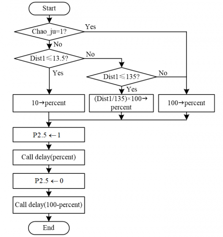
The fan speed governor subroutine can output the PWM wave of the corresponding duty cycle based on the distance between the detected person and the bladeless fan to control the speed of the DC motor and realize the regulation of the blowing velocity of the bladeless fan. The flow chart is shown in Figure 7.
During program design, the duty cycle that the PWM wave output is adjusted by the constant-frequency width modulation, which not only keeps the PWM wave output cycle constant but also changes the times spent for high and low levels it outputs to control the size of PWM wave duty cycle (Mo, 2015). When programming, this system sets the PWM wave output cycle to 10ms. A PWM wave with a duty cycle of percent% is output by the way as follows: First, write a 0.1 ms delay subroutine delay (uchar n); then control PWM wave output the high level, and call delay (uchar n) for percent times; then, control PWM wave output a low level, and call delay (uchar n) for (100-percent) times (Yuan, 2013).
The program flow is given as follows: First, determine whether the ultradistance flag bit Chao_ju is 1, if so (indicating Dist > 150cm), then assign 100 to the duty cycle variable percent; conversely, when Chao_ju = 0, continue to determine which value the Dist1 has. When Dist1≤13.5cm, 10 is assigned to percent; when 13.5cm<Dist1≤135cm, (Dist1/135)´100 is assigned to percent; when Dist1>135cm, 100 is assigned to percent. Then, a high level is output from the SCM pin P2.5 to control the DC motor to operate and delay subroutine delay(percent) is invoked. Finally, a low level is output from the pin P2.5 to cut off the DC motor and calls the delay subroutine delay (100-percent).
Figure 7. Flow chart of fan speed governor subroutine
In order to test the performance of the designed control system for bladeless fan, this system is tested for automatic air blast angle adjustment and speed governor smart control and so on.
5.1. Auto air blast angle adjustment
In order to check whether there is someone within the range of the maximum sensing distance (3m) set by the system, an automatic tracking test on the air blast angle of bladeless fan is performed. Tests discover that when there is someone within the distance of 3m from a bladeless fan and moves around the fan, the system can control the fan rotation angle controller circuit to automatically adjust the blowing angle as the position of human body changes and start blowing after aligning with the human body; if there is none within this range, the system controls the bladeless fan to rotate at a uniform speed at 360 degrees and detects the position of the human body, and prohibit it from blowing until someone is detected, which plays an energy conservation role.
5.2. Speed governor smart control
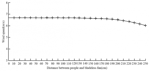
Then, the bladeless fan blasts against the human body in order to detect how the air blowing speed changes at each position when the person moves within the range of 0 ~ 250 cm. In the specific test, a DT-619 type digital wind speed measurer is used (the measurement range is 0.40 ~30.00 m/s, and the measurement accuracy is ±0.01 m/s) to measure the blowing speed at the location of the person once every 10 cm. The data curve is shown in Figure 8. In the figure, the horizontal axis represents the distance (cm) between the human and the bladeless fan, and the vertical axis represents the blowing speed (m/s) at each position.
Figure 8. Curve of blowing speed measurements at each position
As shown in Figure 8, when human moves within a range of 0 to 200 cm from a bladeless fan, the measured blowing speed evolves from 6.59 to 6.68 m/s, and the wind speed fluctuates only by 0.09 m/s. The blowing speed and wind power basically remain constant. When the distance between the human and the bladeless fan exceeds 200 cm, the measured blowing speed slightly decreases. Even when the distance reaches 250 cm, the blowing speed is still 6.01 m/s.
The test results show that the system enables automatic regulation of blowing angle, by which the blowing angle of the bladeless fan is subjected to change with the change of the human body position; while the system can intelligently control the blowing-in speed of the bladeless fan based on the distance between the human and the fan, and provide a constant blowing velocity and wind power within a certain range, so that people get a good breeze. It can be seen that the system has a high level of automation control, and fills the gaps of the original bladeless fan.
This paper proposes a design scheme for a control system for the intellectual bladeless fan. The focus in this paper is placed on the detections of the distance between the human and the bladeless fan with pyroelectric sensor HC-SR501 and infrared sensor GP2Y0A02YK0F. In addition to this, this system can also enable the regulation of bladeless fan blowing velocity by controlling the PWM wave output duty cycle. Tests reveal that this system has a good automatic adjustment of blowing angle, and can intelligently control the bladeless fan's blowing velocity based on the distance between the human and bladeless fan, so that people can get a good breeze and improve the intelligence of the control system for bladeless fan. Today, the system has been applied to real life with good results.
This work was supported by the Science and Technology Research Project of Xianyang City [grant number 2016k02-06].
Deng S. G., Li H. M., Yang X. B. (2016). High-speed induction wireless position detection system based on DSP. Journal of Electronic Measurement and Instrumentation, Vol. 30, No. 6, pp. 880-886. http:/dx.doi.org/10.13382/j.jemi.2016.06.007
Du H. B., Yang K. Z., Kang X. M. (2016). Brushless motor drive scheme based on bipolar PWM wave. Micromotors, Vol. 49, No. 6, pp. 42-45. http:/dx.doi.org/10.3969/j.issn.1001-6848.2016.06.011
Gao F. X. (2016). Vision-based curve tracking system using Fuzzy controller. Control Engineering of China, Vol. 23, No. 1, pp. 149-152. http:/dx.doi.org/10.14107/j.cnki.kzgc.132294
Gao K., Yin X. H. (2017). Design of temperature monitoring system for multi-channel solar panels. Foreign Electronic Measurement Technology, Vol. 36, No. 4, pp. 87-90, 2017. http:/dx.doi.org/10.3969/j.issn.1002-8978.2017.04.021
Guo D. R., Lin X. H., Shan X. (2016). Research on control system of brushless DC motor based on DSP. Foreign Electronic Measurement Technology, Vol. 35, No. 2, pp. 98-101. http:/dx.doi.org/10.3969/j.issn.1002-8978.2016.02.019
Huang J. P., Li Z. D. (2013). Design of ATmega8⁃based infrared guidance system for the blind. Modern Electronics Technique, Vol. 36, No. 13, pp. 128-130.
Li G. Q., Hu Y. J., Jin Y. Z. (2014). Influence of Coanda surface curvature on performance of bladeless fan. Journal of Thermal Science, Vol. 23, No. 5, pp. 422-431. http:/dx.doi.org/10.1007/s11630-014-0725-3
Li Z. F., Guo H. M., Luo H. L. (2015). A constant temperature circuit design applied to the AD converter module. Electrical Automation, Vol. 37, No. 2, pp. 97-99. http:/dx.doi.org/10.3969/j.issn.1000-3886.2015.02.033
Mo H. F. (2015). Design and realization of DC motor speed control system by digital double closed loop. Manufacturing Automation, Vol. 37, No. 2, pp. 153-156. http:/dx.doi.org/10.3969/j.issn.1009-0134.2015.04.050
Wang C. Q., Yan L., Cao W. F. (2014). Design of bladeless fan control system based on BM6201FS. Computer Measurement & Control, Vol. 22, No. 10, pp. 3152-3157. http:/dx.doi.org/10.3969/j.issn.1671-4598.2014.10.022
Wang D., Mo X. (2016). Design and implementation smart home of intelligent lighting system based on STM32 and HC-SR501. Journal of Chongqing University of Technology (Natural Science), Vol. 30, No. 6, pp. 135-142. http:/dx.doi.org/10.3969/j.issn.1674-8425(z).2016.06.023
Wei Q. Y., Zhang T. H., Chen H. W. (2015). Research on the stability of the hotwire wind velocity measurement system with constant temperature control loop. Chinese Journal of Scientific Instrument, Vol. 36, No. 8, pp. 1801-1809. http:/dx.doi.org/10.3969/j.issn.0254-3087.2015.08.015
Yuan Z. J. (2013). Research on PWM regulating speed system of DC motor based on Proteus. Electronic Design Engineering, Vol. 21, No. 15, pp. 113-116. http:/dx.doi.org/10.3969/j.issn.1674-6236.2013.15.034
Yuan Z. J. (2014). Modeling and simulation of cigarette weight control system. Open Cybernetics and Systemics Journal, Vol. 8, No. 1, pp. 155-162.
Zhang X., Zhang H. P. (2015). Research and design of distance measuring and alarming system based on infrared sensor. Coal Technology, Vol. 34, No. 11, pp. 287-290. http:/dx.doi.org/10.13301/j.cnki.ct.2015.11.111