OPEN ACCESS
The paper presents the design and experimental analysis of highway wind mill using savonius wind turbine. The highway wind mill is nothing but the wind mill kept in the mid of the road so that , this wind mill utilize the fast moving wind which is produced from fast moving vehicles travels in the high way. In this work the required wind data have been collected in highways and based on these values the design and fabrication have been made. The output of the wind turbine has been given to the power converter in order to get the constant power output and test has been done on the wind tunnel before implementing in the real application and the results obtained in the wind tunnel test is shown in this paper.
modified savonius wind turbine, boost power converter, highway wind mill, computational fluid dynamics, curtain.
In this work the required wind data have been collected in highways and based on these values the design and fabrication have been made. The output of the wind turbine has been given to the power converter in order to get the constant power output and test has been done on the wind tunnel as described by (Fujisawa et al., 1994), before implementing in the real application and the results obtained in the wind tunnel test is shown in this paper. This energy source has drawbacks related to economics and pollution. To overcome these drawbacks and to improve the power accessibility, generate electricity from the Renewable Energy Sources (RESs) as suggested by (Ganesh et al., 2015), which are preferably available locally and environmentally friendly such as wind, solar and hydropower. Owing to the specific advantages, particularly clean, sustainability, the solar energy and wind energy are promising renewable energies among all other renewable energy sources. This research work mainly concentrates on unused energy which is generated by vehicles running at high speed in the high way. By placing the modified savonius wind turbine in the middle of the high way it acquires wind from all the direction so the wasted energy can be utilized in the effective way. The advantage of modified savonius wind turbine as specified by (Bedri et al., 2015) is that, it is an Omni-directional wind turbine, low cost. This system consists of two curtain arrangements to focus wind on one direction. The modified savonius wind turbine which converts wind energy into mechanical energy. Wind velocity with and without vehicle movement is measured using wind anemometer, Vehicle velocity is measured (for both heavy and light vehicle), Wind sustain time is measured. The simplest possible wind-energy turbine consists of two crucial parts as reminded by (Kamoji et al., 2011), there are, Rotor blade and Shaft. The blades are basically the sails of the system; in their simplest form, they act has barriers to the wind (more modern blade designs go beyond the barrier method). When the wind forces the blades to move, it has transferred some of its energy to the rotor as reminded by (Savonius et al., 1931). The wind shaft is connected to the centre of the rotor. When the rotor spins, the shaft spins as well. In this way, the rotor transfers its mechanical, rotational energy to the shaft, which enters an electrical generator on the other end as explained by (Manwell et al., 2002). The simplest possible wind-energy turbine consists of two crucial parts there are, Rotor blade and Shaft as described by (Sheldahl et al., 1978). The blades are basically the sails of the system; in their simplest form, they act has barriers to the wind (more modern blade designs go beyond the barrier method). When the wind forces the blades to move, it has transferred some of its energy to the rotor. The wind shaft is connected to the centre of the rotor. When the rotor spins, the shaft spins as well. In this way, the rotor transfers its mechanical, rotational energy to the shaft, which enters an electrical generator on the other end. From the collected data the optimum wind velocity is obtained between above half meter from the ground and below one and half meter from the ground. Based on the above constrain the height of the blade is taken as 1m. The breadth of the road divider is 1.5m hence from this constrain the radius is taken as 0.5m and Area =1× 0.5 m2. The basic parameters required in the present study are aspect ratio (H/D), overlap ratio (m/D), blade arc angle (w) and blade shape factor (p/q). Modified Savonius rotors are fabricated from mild steel sheet whose thickness is 2 mm. Rotors are covered at the top and bottom by an acrylic plate of 10 mm thickness. Stainless steel flanges housing the two end shafts are bolted to the two acrylic sheets. In this paper, implementation of vertical axis wind turbine on road dividers which provides effective output operation were analyzed. It can be installed on any highway with the width being the only constraint. The electrical energy conversion system consists of a unidirectional boost converter operates different modes in boost operation and one mode in a buck operation. Simulink model of whole system including unidirectional DC-DC boost converter, bidirectional DC-DC converters were developed for wind energy electrical system and design results were obtained in CFD. A variety of operating conditions from different inputs were analyzed. The system has a robust performance under mode changing while input wind speed changes. The hardware results of the proposed model were verified with design results. The mode changing operation is effectively done in both design and real-time platforms.
In the beginning of 21st century we are in the search of non renewable energy since fast depletion of fossil fuels and pollution as reminded by (Modi et al., 1989). In the highway areas, energy consumers are getting power from only diesel generators as an energy source. This energy source has drawbacks related to economics and pollution. To overcome these drawbacks and to improve the power accessibility, generate electricity from the Renewable Energy Sources (RESs), which are preferably available locally and environmentally friendly such as wind, solar and hydropower. Owing to the specific advantages, particularly clean, sustainability, the solar energy and wind energy are promising renewable energies among all other renewable energy sources. This research work mainly concentrates on unused energy which is generated by vehicles running at high speed in the high way. By placing the modified savonius wind turbine proposed by (Moutsoglou et al., 1995) in the middle of the high way it acquires wind from all the direction so the wasted energy can be utilized in the effective way. The advantage of modified savonius wind turbine is that, it is an Omni-directional wind turbine, low cost. This system consists of two curtain arrangements to focus wind on one direction. The modified savonius wind turbine which converts wind energy into mechanical energy. Then the output from turbine is converted into to electrical energy with help of Generator and it is stored in the battery with the help of bidirectional converter.
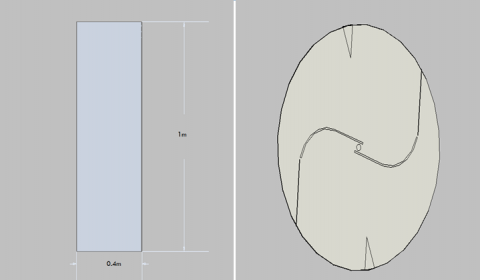
Wind velocity with and without vehicle movement is measured using wind anemometer, Vehicle velocity is measured (for both heavy and light vehicle), Wind sustain time is measured. From the collected data the optimum wind velocity is obtained between above half meter from the ground and below one and half meter from the ground. Based on the above constrain the height of the blade is taken as 1m. The breadth of the road divider is 1.5m hence from this constrain the radius is taken as 0.5m and Area =1× 0.5 m2.
Table 1. Wind data collection
|
S. No |
Actual wind velocity without vehicle |
Light vehicles |
Heavy vehicles |
||||
|
Wind speed (m/s) |
Wind sustain time (sec) |
Vehicle velocity (km/hr) |
Wind speed (m/s) |
Wind sustain time (sec) |
Vehicle velocity (m/s) |
||
|
1 |
4.7 |
5.4 |
15 |
60 |
7.4 |
30 |
50 |
|
2 |
6.2 |
8.8 |
12 |
90 |
8.0 |
35 |
65 |
|
3 |
4.5 |
5.0 |
15 |
50 |
8.2 |
25 |
70 |
|
4 |
6 |
9.2 |
20 |
95 |
7.7 |
30 |
60 |
|
5 |
5.1 |
7.4 |
18 |
70 |
7.5 |
27 |
58 |
|
6 |
6.5 |
7.8 |
10 |
80 |
9.5 |
32 |
75 |
|
7 |
9 |
11 |
17 |
110 |
10.2 |
29 |
80 |
The output power of a wind energy system is directly proportional to swept area of the rotor and the output power is directly proportional to triple the velocity of wind.
The basic calculations of wind energy conversion system are as follows
Kinetic Energy = 0.5 x Mass x Velocity2 (1)
Mass =Velocity x Area x Density (2)
P = 0.5 x ρ x A x CP x V3 (3)
Where,
P = Mechanical power in watts.
ρ = Air density (about 1.225 kg/m3 at sea level)
A = Rotor striking area, exposed to the wind (m2)
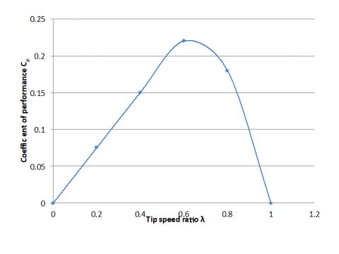
CP = Coefficient of performance
V = Wind speed (m/s)
Figure 1. Tip speed v/s Cp
From the above graph for TSR = 0.35 coefficient of performance Cp = 0. (4)
From power equation P = (1/2) x (ρ) x (A) x (CP) x (V3) (5)
P = (0.5) x (1.225) x (0.5 x l) x (0.11) x (93) = 25W (6)
Table 2. Calculation of theoretical wind power at various wind velocity
|
Wind speed (km/hr) |
Wind speed (m/s) |
Calculated mechanical power in watt |
Electrical power = 0. 4×mech.power watt |
|
0 |
0 |
0 |
0 |
|
5 |
1.385 |
0.089 |
0.035 |
|
10 |
2.770 |
0.715 |
0.286 |
|
15 |
4.155 |
2.410 |
0.966 |
|
20 |
5.540 |
5.720 |
2.290 |
|
25 |
6.925 |
11.180 |
4.470 |
|
30 |
8.310 |
19.320 |
7.730 |
|
35 |
9.695 |
30.690 |
12.270 |
|
40 |
11.080 |
45.810 |
18.320 |
|
45 |
12.465 |
65.230 |
26.090 |
Assume 40% efficiency to convert mechanical power in to electrical power.
So, Electrical power = 0.4 x mechanical power
= 0.4 x 25 = 10 W.
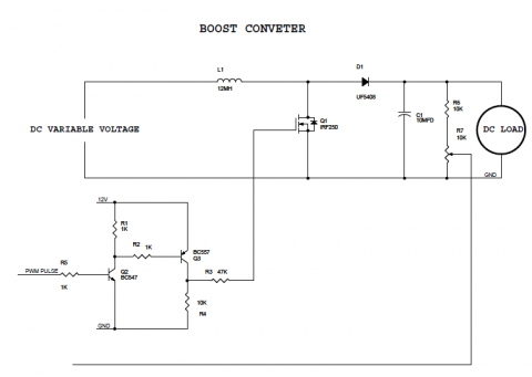
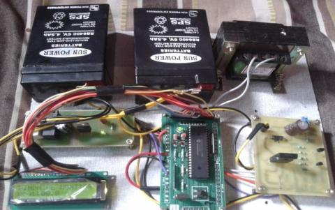
The output voltage from the generator is varying according to variable wind velocity but constant input of 12V is given to the battery. For giving constant input to the battery power converter circuit is required. The power converter circuit which is used here is boost converter for step up the voltage.
4.1. Design of DC to dc power converter circuit
According to design the DC-DC power converter is modelled in MATLAB.
Figure 2. DC to DC power converter
4.2. Design of savonius blade and curtain
The simplest possible wind-energy turbine consists of two crucial parts there are, Rotor blade and Shaft). The blades are basically the sails of the system; in their simplest form, they act has barriers to the wind (more modern blade designs go beyond the barrier method). When the wind forces the blades to move, it has transferred some of its energy to the rotor. The wind shaft is connected to the centre of the rotor. When the rotor spins, the shaft spins as well. In this way, the rotor transfers its mechanical, rotational energy to the shaft, which enters an electrical generator on the other end.
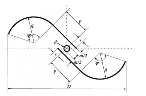
4.3. 2D View of the savonius blade
Figure 3. 2D view of savonius blade
4.4. Savonius blade design geometrical parameters
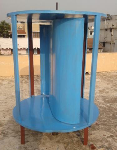
The basic parameters required in the present study are aspect ratio (H/D), overlap ratio (m/D), blade arc angle (w) and blade shape factor (p/q). Modified Savonius rotors are fabricated from mild steel sheet whose thickness is 2 mm. Rotors are covered at the top and bottom by an acrylic plate of 10 mm thickness. Stainless steel flanges housing the two end shafts are bolted to the two acrylic sheets.
Figure 4. Modified savonius wind turbine with curtain arrangements
The designed normal (semi-circular) savonius wind turbine (NSWT) and the modified savonius wind turbine (MSWT) with and without curtain is subjected to CFD analysis in Fluent Software. The Wind velocity acting on the blade for both normal and modified savonius blade is 9m/s, for normal savonius blade the outlet wind velocity is 9.92 m/s and for modified savonius blade the outlet wind velocity is 11.813. The outlet velocity increases by approximately 2 m/s for modified savonius wind turbine. Hence the modified savonius blade is suitable for the available wind velocity. The velocity and pressure diagrams are given below.
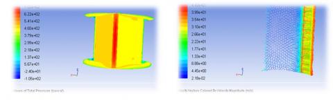
Figure 5. Pressure and velocity acting on MSWT without curtain
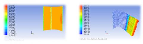
Figure 6. Pressure and Velocity acting on MSWT with curtain
The Wind velocity acting on the blade for both normal and modified savonius blade is 9m/s, for normal savonius blade the outlet wind velocity is 9.92 m/s and for modified savonius blade the outlet wind velocity is 11.813. The outlet velocity increases by approximately 2 m/s for modified savonius wind turbine. Hence the modified savonius blade is suitable for the available wind velocity. The velocity and pressure diagrams are given. By placing a curtain, the inlet wind velocity acting on the blade is 9 m/s. The pressure acting on the blade without curtain is 477.96 pascal and the outlet velocity is 11.183 m/s. The pressure acting on the blade with curtain is 614.734 pascal and outlet velocity is 12.06 m/s. comparing the modified savonius wind turbine with and without curtain the pressure acting on the blade increases by 136.767 pascal and velocity outlet increases by 1m/s.
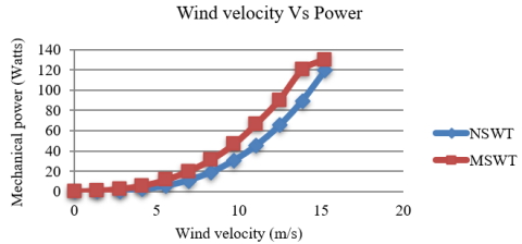
The output load performance of the wind turbine has been measured by using multimeter. The anemometer is used to measure the velocity of the wind and the corresponding open-end voltage to be generated by the PMDC motor is measured and the readings are tabulated. The output voltage from the PMDC motor is varying according to the varying wind velocity. So the output is directly given to the boost converter to give constant input to the battery. The battery which is used here is the lead acid battery.
Table 3. Calculation of experimental wind power at various wind velocity
|
Wind speed (km/hr) |
Wind speed (m/s) |
Electrical power output in watt |
|
0 |
0 |
0 |
|
5 |
1.385 |
4.5264 |
|
10 |
2.770 |
8.0532 |
|
15 |
4.155 |
12.5036 |
|
20 |
5.540 |
17.976 |
|
25 |
6.925 |
26.898 |
|
30 |
8.310 |
35.426 |
|
35 |
9.695 |
46.872 |
|
40 |
11.080 |
60.120 |
|
45 |
12.465 |
78.136 |
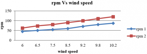
Then the speed of the rotor has been measured using torque transducer. The speed of the normal savonius blade which is taken as rpm 1 and the speed of the modified savonius blade which is taken as rpm 2 which is shown in the table below.
Figure 9. Graph shows the mechanical power vs wind velocity
Table 4. Calculation of experimental wind power at various wind velocity
|
V(m/s) |
RPM 1 |
RPM 2 |
|
6 |
46 |
62 |
|
6.5 |
50 |
73 |
|
7.5 |
55 |
80 |
|
8.5 |
60 |
90 |
|
9.2 |
71 |
99 |
|
9.8 |
80 |
110 |
|
10.2 |
87 |
121 |
Figure 10. Graph showing the wind speed Vs rpm
In this paper, implementation of vertical axis wind turbine on road dividers which provides effective output operation were analyzed. It can be installed on any highway with the width being the only constraint. The electrical energy conversion system consists of a unidirectional boost converter operates different modes in boost operation and one mode in a buck operation. Simulink model of whole system including unidirectional DC-DC boost converter, bidirectional DC-DC converters were developed for wind energy electrical system and design results were obtained in CFD. A variety of operating conditions from different inputs were analyzed. The system has a robust performance under mode changing while input wind speed changes. The hardware results of the proposed model were verified with design results. The mode changing operation is effectively done in both design and real-time platforms. Since the battery is portable, we can use it in some other location for any low voltage purpose. It will provide effective solution for the boom of the electrical energy by the society.
Bedri K., Muğdeşem T., Ali E. (2015). Wind tunnel performance data for two and three bucket Savonius rotors. J Acta Polytechnica Hungarica, Vol. 12, No. 3, pp. 199-211.
Fujisawa N., Gotoh F. (1994). Experimental study on the aerodynamic performance of a savonius rotor. Sol Energy Eng Trans ASME, Vol. 116, pp. 148-152. https://doi.org/10.1115/1.2930074
Ganesh G., Vijay-Kumar G., Vijay-Babu A. R., Srinivasa R. G., Tagore Y. R. (2015). Performance analysis and MPPT control of a standalone hybrid power generation system. J Electrical Engg, Vol. 15, No. 1, pp. 334-343.
Kamoji M. A., Kedare S. B., Prabhu S. V. (2011). Experimental investigations on modified Savonius rotor. Wind Engineering, Vol. 35, pp. 483-510. https://doi.org/10.1260/0309-524X.35.4.483
Manwell J. F., McGowan, J. G., Rogers A. L. (2002). Wind energy explained: theory, design and application. John Wiley, England. https://doi.org/10.1002/0470846127
Modi V. J., Fernando M. (1989). On the performance of the Savonius wind turbine. J Sol Energy Eng, Vol. 111, pp. 71-81. https://doi.org/10.1115/1.3268289
Moutsoglou A., Weng Y. (1995). Performance tests of a benesh wind turbine rotor and a Savonius rotor. Wind Engg, Vol. 19, No. 6, pp. 349-362.
Savonius S. J. (1931). The S-rotor and its applications. Mech Engg, Vol. 53, No. 5, pp. 333-338.
Sheldahl R. E., Blackwell B. F., Feltz L. V. (1978). Wind tunnel performance data for two and three bucket Savonius rotors. J Energy, Vol. 2, pp. 160-164. https://doi.org/10.2514/3.47966