OPEN ACCESS
In solar power tower plant, the amount of energy exploited of direct solar radiation depends to the angle between the solar rays and the heliostat position in the solar field. The maximum incident solar radiation on the heliostat be when the sunrays are perpendicular to the heliostat reflection area. That cannot exist in full sunny day for reason of cosine loss effect due by the variation of the sun position, which affected the efficiency of a heliostat. This paper shows new approach of installing the mobile target of sunrays receiver to minimize the cosine losses of the heliostat field in the solar power tower plant for increasing his efficiency. The simulation results validated the advantage of uses the mobile target in the central solar tower. In addition, it illustrates the possibility of eliminating the cosine losses based on changing the target position.
heliostat, centrale solaire a tour, pertes cosinus, cible
The recent technology development that we are living in it today create a catastrophic result of pollution by amount of energy consumption produced by fossil or chemical sources, for this reason the country and governmental organizations are thinking to transfer to the green sources and technologies. The central solar tower is one of green technologies used to generate the electricity from sunlight by concentering the solar rays at the top of the tower. The absorption system at the top of tower used to convert this ray to the heat energy to turn drive stream turbine. In solar power plant may heliostats installed to ensure the big amount of reflection the sunrays. This machine has a reflection area and a studied position in the field of the central solar, they follow the sun motion by tracking system (Chen et al., 2004; Guo et al., 2013).
In reality the reflection of sun rays do not ensure with high amount in fully sunny day for reason of the efficiency of heliostats reflection area, tracking system mode and the position of each heliostat in the solar power plant. The cosine effect is one of parameters have an important influence in the global efficiency of solar tower palnt.in this works we have studied this phenomena and propose a solution can minimize this effect for improve the performance of the solar power plant.
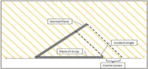
In optics, the law cosines of Lambert said that the radiation intensity or the light intensity observed from a reflective surface is directly proportional to the cosine of the angle θ between the direction of the incident light and the surface normal sensor (Warren and Smith, 2008). The law is also known as Lambert's emission law (Pedrotti and Pedrotti, 1993) or the cosine emission law. It is named after Johann Heinrich Lambert, from his Photometry, published in 1760 (Lambert, 1760). The cosine effect has been modeled follows in the Figure 1.
Figure 1. Illustration of cosine losses (Clifford, 2012)
Irradiance falling on surface is proportional to the cosine of the angle between the incident light direction and the surface normal (this angle is contained in the range 0 (when light is perpendicular to the surface) to 90 degrees (Clifford, 2012).
The cosine losses are realized whenever the sensor is not oriented perpendicularly to the rays of the direct solar radiation. To reduce the effect, collectors are tilted horizontally or are constantly moved by trackers in an attempt to maintain the angle of incidence as close to ninety degrees as possible at all times. This technique can be used for solar photovoltaic systems; but in a solar tower(s) it is impossible to do this because the target or tower is fixed, because of this point it has been proposed to add other solar receivers in order to increase the efficiency of the power plant and minimize the cosine effect.
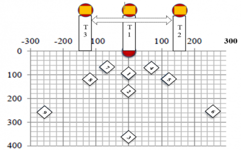
A multi-turn solar power plant (MTSPP) is a new concept of a focal point followed in two axes of concentration of the central solar energy (Figure 2). The MTSPP consists of several receivers mounted on a tower that stand so close to one another that the fields of the heliostat towers overlap in part. Consequently, in some regions of the total heliostat field, the heliostats are alternately directed to different points of sight on the different towers. Thus, the SSMT uses the radiation that remains generally used by a conventional system of the solar tower due to mutual blocking of the heliostats.
The field configuration of a heliostat in MTSPP can be optimized to achieve a high annual efficiency for the use of available beam energy that would otherwise strike the ground or on the roof below. In this case the heliostats are not directed to the nearest tower; they are directed towards the receiver where the cosine effect will be the smallest, so the heliostats are alternately directed towards the three towers. MTSA reduces the losses caused by the cosine effect of the heliostats in the solar field. In this work, the distance between the heliostat and the tower has no meaning; the main idea based on the angle beta (cosine effect).
Figure 2. Placement of the heliostats (in m) according to the height of the tower
3.1. The parameters of the simulation
The fixed parameters:
Day: 19
Month: February
Height of tower: 50 meters
Receiver Tilt: 20°
Mirror reflection coefficient: 0.9
The surface of the heliostat: 2x2m
Variable parameters:
Hours (07: 00 - 17: 00)
Number of heliostat (9).
3.2. Calculate the cosine loss in a solar tower (Robert, 2012)
The following figure illustrates the image of a heliostat with the necessary parameters to determine the cosine effect.
Figure 3. Effect of cosine loss on radiant power reflected by heliostat (sola power tower) (Robert, 2012)
The equation of the loss due to the cosine effect is given by:
$Q _ { ( e f f , \mathrm { cos } ) } = 1 - \cos \beta$
Radiation power is calculated by the following equation:
$P _ { ( r a d ) } = I _ { d i r } \times A _ { e f f }$
The effective area is calculated by the following equation:
$A _ { e f f } = A _ { \operatorname { mir } } \times \cos \beta$
Area or surface of the mirror is a fixed parameter (the design of the heliostat).
Beta angle varied throughout the day; in the case where the heliostat reflected the incident rays towards a fixed whole one cannot optimize its value because: The sun in motion, the heliostat in motion, the tower (the target) is fixed.
The best solution to optimize the value of the beta angle is to change the position of the receiver of such spell that the beta angle is always about zero (cosβ = 1). To solve this problem, it is necessary to develop a system of such spells that the angle beta is always about zero (cosβ = 1). And thus the cosine effect can be reduced by a change in the position of the receiver. Assuming that the tower changes its position as a function of time to optimize the cosine effect; in the ideal case, the angle beta forming between the incident ray and the ray reflected towards the receiver is always equal to 90° in the azimuth plane.
4.1. Simulation of the cosine effect
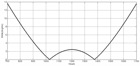
Solar field design with a single heliostat and solar tower, Figure. 4 shows the evolution of the angle beta between the incident rays and reflects towards the receiver at the azimuth level; this angle varied 0 and 14° during the day 50 (19 February). Between (7:00 am and 5:00 pm).
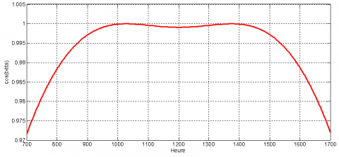
Of the same the Figure 5 illustrates the cosine evolution of the angle of Figure. 4 throughout the day.
Figure 4. Variation of the beta angle throughout the day (between 08:00 and 17:00)
Figure 5. Variation of the cosine beta angle throughout the day (between 08:00 and 17:00)
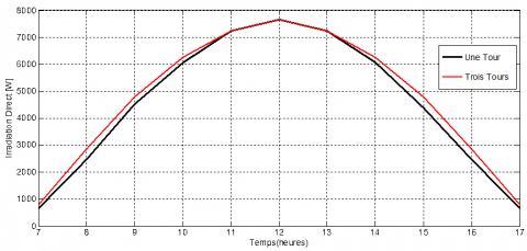
According to the results presented in Figure. 6-8, it is noted that the solution for decreasing the cosine effect in a solar power plant is to increase the number of receivers or to mobilize this position as a function of time day. Because the more the number increases the cosine effect decreased and the efficiency of the plant increases.
Figure 6. Simulated result of direct irradiation received by one and three towers
Figure 7. Simulated result of direct irradiation received by one, three and five towers
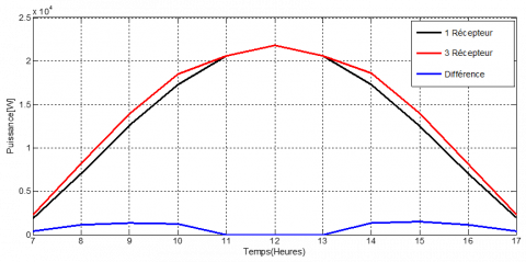
Figure. 8 shows the difference of the power between a solar power plant with one and three towers.
Figure 8. Simulated result of direct irradiation received by one, three and the difference between them
In this work, we have shown the possibility of minimizing the cosine loss in a solar power tower; this technique is based on changing the position of solar receiver. We noticed that the more the number of revolutions increases the smaller the cosine effect and it means the increase in efficiency in a solar power tower plant.
Comparing the three configurations. We can note that the central with five receivers, it shows an increase in the power of the solar power towers plant.
The results presented in this study are very encouraging, because from changing the position of solar receiver, it will be possible to further increase the performance of the solar power plant towers.
Chen Y. T., Kribus A., Lim B. H., Lim C. S., Chong K. K., Karni J., Buck R., Pfahl A., Bligh T. P. (2004). Comparison of two sun tracking methods in the application of a heliostat field. Journal of Solar Energy Engineering, Vol. 126, No. 1, pp. 7. https://doi.org/10.1115/1.1634583
Guo M. H., Sun F. H., Wang Z. F., Zhang J. (2013). Properties of a general azimuth–elevation tracking angle formula for a heliostat with a mirror-pivot offset and other angular errors. Solar Energy, Vol. 96, pp. 159-167. https://doi.org/10.1016/j.solener.2013.06.031
Ho C. K., Brian D. I. (2014). Review of high-temperature central receiver designs for concentrating solar power. Sustainable Energy Rev. Vol. 29. pp. 835-846. https://doi.org/10.1016/j.rser.2013.08.099
Lambert J. H. (1760). Photometria, sive de mensura et gradibus luminis. Colorum et Umbrae.
Meyers R. A. (2012). Encyclopedia of Sustainability Science and Technology. https://doi.org/10.1007/978-1-4419-0851-3
Pedrotti F. J., Pedrotti L. S. (1993). Introduction to optics. Prentice Hall. pp. 4. https://doi.org/10.1007/b106780.
Warren J. (2008). Smith, Modern Optical Engineering, Vol. 4.