OPEN ACCESS
With the aid of the Matlab, this paper analyses the safety of the modelling and control strategy for digital push-pull switched mode power supply. Firstly, the topology of the power supply was subjected to an safety analysis, and a digital simulation model of the power supply was set up on the Simulink module. Based on the model, the author designed a digital proportional-integral-derivative (PID) control algorithm, and compared it with the incremental PID control algorithm. The results show that the digital PID control algorithm is faster and more accurate than the contrastive algorithm. The research findings provide a good reference for the design of digital switched mode power supplies.
push-pull, switched mode, power supply, proportional-integral-derivative (PID) control, matlab
In recent years, with the development of semiconductor technology, electronic equipment is developing toward miniaturization, high-speed, intelligent direction (Louis et al., 2016; Guilbert et al., 2015). But the traditional analog control switching power supply cannot meet all the application requirements, so it is urgent to realize the digital and intelligent functions of the switching power supply in various engineering applications (Takaku et al., 2010).
The core of digital power supply is digital processing controller, which generates PWM signal by software algorithm and drives power switch to control power loop. The digital power supply can monitor the internal working state of the power supply and communicate with the external system. The internal state of the power supply is provided to the whole system. The digital control power supply system includes digital circuit, interface circuit and some analog circuits. Among them, analog circuit mainly refers to the power part of the system, including magnetic components, switching rectifier devices, resistance and capacitance; digital circuit mainly includes digital processing chip; interface circuit mainly includes analog-to-digital converter and interface circuit for communication (Newns et al., 2012; Karimi et al., 2008).
In the prospect of high-speed digital development of switching power supply, digital control is introduced into switching power supply, and digital PID control strategy is used to optimize the design of switching power supply. Digital PID algorithm has been a mature technology in the field of control engineering, because it does not need to establish a mathematical model, has the advantages of flexible parameter control, strong adaptability, strong robustness, easy to implement. Digital PID divides position PID and incremental PID, because the output of position PID is related to the previous state of the system, and also needs the accumulative value of the error; the output state of incremental PID is only related to the current state and the past two states, and has nothing to do with other states. Otherwise, the relative stability is poor, and the output of incremental PID is control increment. If the processor has an unexpected error, the incremental PID control system has fewer malfunctions, and the processor has memory function, can maintain the current state, will not have a great impact on the entire system, so incremental PID is more widely used in practical applications. General. Therefore, this paper studies and improves the incremental PID in push-pull switching mode power supply (Kundrukote, 2013; Hojo et al., 2013; Miguez et al., 2015; Wei et al., 2009; Huang & Mazumder, 2009).
In this paper, we analyzed the safety of the push-pull switching power supply topology, and built the digital simulation model of push-pull switch power with the Simulink module. On the basis of the model, we improved the incremental PID control algorithm and compared the incremental PID with the improved PID control algorithm for research (Mole et al., 2016; Yurkevich & Naidu, 2012).
Switching power supply is a kind of circuit equipment which can output stable DC voltage by controlling the turn-on and turn-off time of the circuit. With the continuous development of electronic equipment, the field of switching power supply has become more and more mature, more and more widely used, making switching power supply has become an indispensable way of electronic equipment power supply system.
The United States began to use switching power supply in the 1950s. Due to the development of military power supply, switching power supply should have the following advantages: miniature, lightweight, stability and other advantages, and gradually applied to electronic, communications, microcomputer and other fields.
After the continuous exploration and development of people, the switching power supply has made great breakthroughs in many aspects. With the emergence of high power MOSFET and IGBT, switching power supply is developing towards high frequency, high stability and high power. Software technology can also improve the switching power loss and noise, so that the performance of the switching power supply can be further improved to achieve high-frequency switching power supply.
The converter technology of switching power supply is mainly composed of PWM converter, resonant converter and software switching converter. PWM converter is popular on the market now, its anti-interference ability is strong, so that the digital signal in the transmission process will be less noise signal interference to the minimum, and the realization of PWM converter circuit size is small, low price, has been recognized by industry enthusiasts.
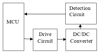
PWM wave modulation is adopted in the design of push-pull switching power supply, which has the advantages of high output power, small output voltage ripple and high efficiency. This paper studies the digital modeling and control strategy simulation of push-pull switching power supply. The principle block diagram of a digital switching power supply is shown in Figure1. The DC / DC converter, supplemented by drive circuit and voltage detection circuit, realizes the PID voltage stabilization algorithm under the control of MCU. It is also a common method to realize the digital switching power supply.
Figure 1. The principle block diagram of a digital switching power supply
In order to make the hardware, modeling and simulation of engine dynamic system need to be studied at the early stage in design and development. Simulink module has a strong dynamic simulation performance for power electronic device with nonlinearity, which full fill the simulation requirement of digital switching power supply. Building the simulation model, not only verify the feasibility of the project, but also provide convenience for the PID parameter tuning and digital control procedures. The method has an important significance in the development of digital switching power supply that software simulation guide hardware design.
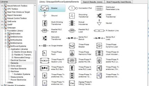
3.1. Sim power systems model library
Sim Power Systems is an ideal tool for digital switching power system simulation. Different from the simulation software such as Pspice and Saber, the model in Sim Power Systems pays more attention to the external characteristics of the device and is easy to connect with the control system. Sim Power Systems model library contains common power supply, power electronic devices and corresponding control measurement modules. Using these modules to simulate digital switching power supply can simplify the programming work and describe the electrical system model intuitively and graphically.
Sim Power Systems model can be connected with other Simulink modules for integrated system-level dynamic analysis, but the two modules are used in different ways. The former module must be connected in the circuit, each module has input and output, in the circuit flow is the current, current flow through the device will produce voltage drop. The latter module is composed of signal flow, and the signal flowing into and out of the module has no specific physical meaning, which depends on the simulation model object. In the application of power electronic system simulation, the Simulink module is used.
Figure 2. The principle block diagram of a digital switching power supply
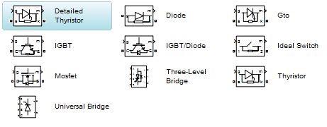
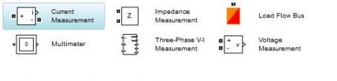
The capacitance, resistance, inductance and transformer models commonly used in power electronic simulation are shown in Figure 2. The semiconductor diode and switch tube models are shown in Figure 3. The measurement device models including voltage and current detection are shown in Figure 4.
Figure 3. The principle block diagram of a digital switching power supply
Figure 4. The principle block diagram of a digital switching power supply
3.2. Basic topology of push-pull converter
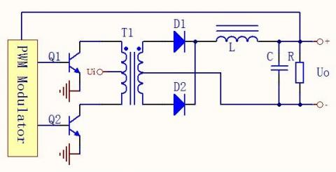
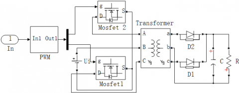
Figure 5 shows the push-pull topology, energy transfer to the secondary windings of transformer through that each of the Q1 and Q2 switch tube alternatively performs a turn-on operation and a turn-off operation controlled by two different PWM produced from pulse-width modulator. The output voltage signal is delivered to pulse width modulator which make up a closed loop system to adjust the PWM duty ratio so that keep the output voltage steady. Such as the TL494 and SG3525, traditional PWM control technology is almost based on integrated circuit chip, the feedback signal is delivered to the reference input of integrated error amplifier which compared it to the aw-toothed waveform voltage produced by the internal oscillator to adjust the duty ratio of the PWM. Digital switching power supply usually take MCU and DSP as the control core, a microprocessor is used to modulate the duty ratio of PWM in PID regulation according to the deviation between the preset voltage and the feedback voltage.
Figure 5. The push-pull topology
3.3. Push-pull pulse width modulator model
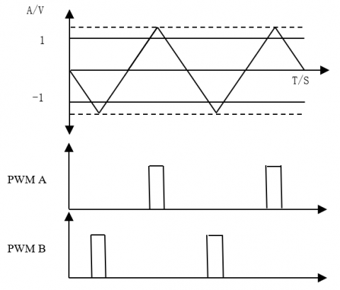
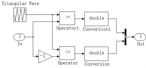
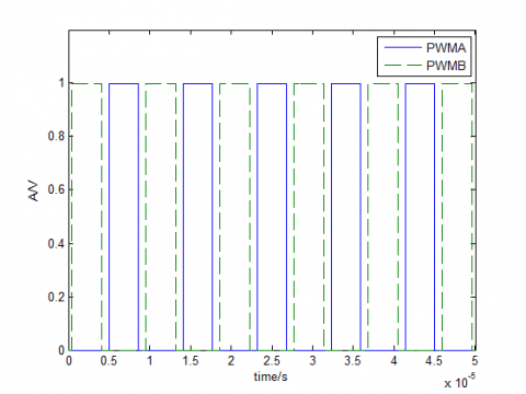
The push-pull type pulse width modulator realizes the 180˚ phase differential modulation of two channel output of identical frequency pulse signals to prevent two switch tube turn on at the same time. Figure 6 shows the principle of pulse width modulation basis on MATLAB/simulink, Comparing the modulation signals of opposite polarity with the carrier signal of isosceles triangle wave. When the carrier signal is greater than the positive modulation signal is obtained when the output is high level, the output of a road wave, the opposite when the carrier signal is greater than the negative modulation signal is obtained when the low level output, another wave, both the phase difference of 180˚. Figure 7 shows the model of pulse-width modulator. Figure 8 shows the output waveform of the PWM module.
Figure 6. Principle of PWM
Figure 7. The model of pulse-width modulator
Figure 8. The output waveform of the PWM module
3.4. Modeling of switching power supply system
Sim Power Systems model library under Simulink environment provides an ideal tool for power electronic system simulation, including electronic devices commonly used modules can be connected to other Simulink modules, switching power supply system model as shown in Figure 9. Where PWM is the subsystem of dual pulse width modulator package, pulse width and frequency for 100kHz design, two FET controlled by two control signals alternately on and off for Ui high speed switching converter input voltage, 18~36V variable. Transformer voltage ratio is 1:1, one side of the center tapped winding method, the inductance and the two side inductance are 100μH. Diode D1 and D2 components of the half wave rectifier, L for the output filter inductor, C for the output filter capacitor, R for the load resistance.
Figure 9. The model of switching power supply system
The computer control system calculates the control quantity by sampling control and according to the deviation of sampling time, so it is necessary to discretize the continuous PID control algorithm. The digital PID control algorithm is divided into position PID control algorithm and incremental control algorithm. First of all, the two algorithms are analyzed, and the algorithm with better control effect is selected.
4.1. Incremental PID
The position PID control algorithm is:
$\mathrm { u } ( n ) = K _ { p } e ( n ) + K _ { i } \sum _ { j = 0 } ^ { n } e ( j ) + K _ { D } [ e ( n ) - e ( n - 1 ) ]$
Among them, n - sampling sequence number, n=0, 1, 2...
u(n)computer output value at the n sub sampling time;
e(n) the deviation value at the n sub sampling time.
e(n-1) the deviation value of the n-1 sampling time.
$K _ { i } = \frac { K _ { p } T } { T _ { l } }$ is the integral coefficient.
$K _ { d } = \frac { K _ { p } T _ { d } } { T }$ is a differential coefficient.
Since the output u(n) of the controller directly controls the actuator, the value of u(n) corresponds to the position of the actuator, it is often referred to as a position-based PID control algorithm. The disadvantage of this algorithm is that the current output is related to the past state, and the computation requires cumulative e u(n). The computation of a computer is very heavy, and the output of u(n) corresponds to the actuator. In the actual position, if the computer fails, a large change in u(n) will result in a significant change in the position of the actuator. This situation is usually not allowed in production practice, and in some cases may lead to major production accidents. As a result, an incremental PID control algorithm is created.
$u ( n - 1 ) = K _ { p } \left[ e ( n - 1 ) + \frac { T } { T _ { I } } \sum _ { j = 0 } ^ { n - 1 } e ( j ) + \frac { T _ { D } } { T } ( e ( n - 1 ) - e ( n - 2 ) ) \right]$
Hypothesising: $\triangle u [ n ] = u ( n ) - u ( n - 1 )$
Incremental form expression:
$\triangle u [ n ] = K _ { p } \{ e ( n ) - e ( n - 1 ) \} + \frac { T K _ { p } } { T _ { I } } e ( n ) + \frac { K _ { p } T _ { d } } { T } \{ e ( n ) - 2 e ( n - 1 )$$+ e ( n - 2 ) \}$
Incremental form expression:
$\begin{aligned} & u [ n ] = u ( n ) - u ( n - 1 ) \\ = & K _ { p } \left[ \mathrm { e } ( n ) - \mathrm { e } ( n - 1 ) + K _ { i } \mathrm { e } ( n ) \right.\\ + &\left. K _ { d } ( \mathrm { e } ( n ) - 2 \mathrm { e } ( n - 1 ) + \mathrm { e } ( n - 2 ) ) \right] \end{aligned}$
As can be seen from the above formula, since the general computer control system uses a constant sampling period T, once the Kp,
K and Kp are determined, as long as the deviation of the three measured values can be obtained by using the above equation before and after the control increment is used. When using the incremental algorithm, the computer controlled increment delta Δu(n) corresponds to the incremental location of the actuator. The control quantity $\Delta \mathrm { u } ( n ) = \sum _ { j = 0 } ^ { n } \Delta u ( j )$, which corresponds to the actual position, needs to be solved by some methods, such as using accumulative elements; at present, the calculation formula $\mathrm { u } ( n ) = u ( n - 1 ) + \Delta u ( n )$Although incremental control has only made some improvements in the algorithm, it has brought many advantages:
(1) because of the increasing output of computers, the effect of failures is very small. If necessary, logical judgement can be used to remove it.
(2) when manual / automatic switching is made, the impact is very small, so it can be easily switched without interference. In addition, when the computer fails, the output channel or actuator has the function of signal latching, so the original value can still be maintained.
(3) The control increment Delta U(n) is only related to the nearest n sampling values, so it is easier to obtain better control effect by weighting. Therefore, in the actual control, the incremental algorithm is more extensive than the location algorithm.
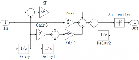
In this modeling, the incremental PID algorithm is used to achieve steady output. When there is a deviation between the output voltage and the set value, the control increment of PWM wave generated by PID operation is fed into the PWM generator, which makes the duty cycle increase or decrease a certain control increment, and the control output voltage is close to the set value little by little. At the same time, integral separation processing is carried out on the basis of incremental PID to further improve the performance of PID controller.
Simulink incremental PID simulation model shown in Figure 10, Unit delay the module retains the deviation for several moments, and achieve the incremental function of the cumulative. As the push-pull PWM converter duty cycle should not be greater than 50%, So the cumulative increase should be limited, then set the PID operation output value of the upper limit of 0.5, the lower limit of 0.
Figure 10. Incremental PID simulation model
4.2. Improved incremental PID
When the switching power supply system is started, the output voltage and the set voltage will be a greater deviation, this deviation value is accumulated after the integral term, it is possible to increase the control incrementally or even exceeding controller limits, it may be prone to overshoot or shock. In order to improve the control effect and Speed up response time, at the same time integrating the separation on the basis of incremental PID, An Improved Expression of Incremental PID Control Algorithm for Integral Separation:
$u ( k ) - u ( k - 1 ) = K _ { P } \left[ \begin{array} { c } { e ( k ) - e ( k - 1 ) + \beta \frac { T } { T _ { I } } e ( k ) } \\ { + \frac { T _ { D } } { T } ( e ( k ) - 2 e ( k - 1 ) + e ( k - 2 ) ) } \end{array} \right]$
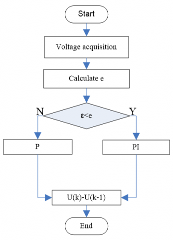
The basic idea of integral separation is set the threshold ε, When the error is greater than the threshold β and the value of β is 0, The integral action will be canceled; PID control, When the error is less than the threshold β and the value of β is 1, The system will add the integral action and PID begins to function.
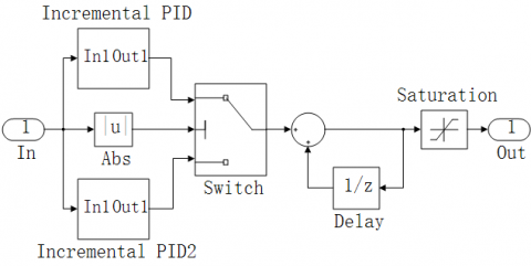
In this improved design, not only in the case of large errors to cancel the integral role, but also two sets of different PID parameters are used for different threshold ranges, so as to improve the control effect. In the Simulink environment, the Switch module is used to realize the switch function, When the absolute value of the error is greater than or equal to the threshold value, the switch module turns on; When the absolute value of the error is less than the threshold value, the switch module is turned on. According to the actual control effect, Take the threshold ε = 2, The improved incremental program implementation is shown in Figure 11 below.the improved incremental PID model with integral separation is shown in Figure 12.
Figure 11. Flow chart of incremental PID program
Figure 12. Improved incremental PID model
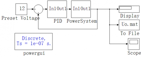
5.1. Control system model
Control strategy is researched under the Power System of Package subsystem that the is connected with the PID model, which is convenient for the PID parameter tuning and system dynamic analysis, Figure 13 shows the feedback control system model. The sample time of PID is 100 us, the incremental PID has the best control effect when PID parameters is setting Kp=0.002, Ki=20, Kd=0. The improved PID selection threshold is 2, the error is greater than the threshold value Kp1=0.03, Kd1=0, and the error is less than the threshold value, Kp2=0.1, Ki2=200, Kd2=0.
In order to obtain clear control effect images, the output voltage data into the work space by using the To File module, drawing dynamic curve by using MATLAB function.
Figure 13. Control system model
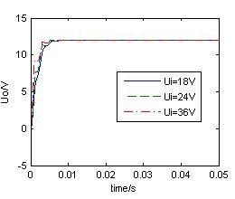
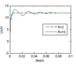
5.2. Contrast on the control effect
Set a fixed load are 2Ω, and input voltage can select 18V, 24V or 36V, while the system is controlled by the incremental PID algorithm. Figure 14 shows the output voltage curve. We can see the setting time of the system is about 8ms, but the output has low accuracy. Set the fixed input voltage are 36V, and the load can select 2Ω or 10Ω. Figure 15 shows the output voltage state curve, the curve will be a shock and have a longer setting time in such a situation.
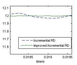
Set the input voltage is 36V, the load is 2, compare the curve of system output while the system is controlled by two different PID strategy, and Figure 16 shows the curve compare, Figure 17 shows the output voltage ripple. The improved incremental PID has shorter setting time and more stable output than incremental PID. Set the input voltage is 36V, and the load can select 2Ω, 10Ω or 50Ω while the system is controlled by the improved PID, Figure 18 shows the output voltage state curve. As can be seen from Figure 18, improved PID control strategy in the switching power supply light load and heavy load both has better control effect.
Figure 14. Fixed load, variable input
Figure 15. Fixed input, variable load
Figure 16. Curve comparing
Figure 17. System ripple
Figure 18. Improved incremental PID control effect
This paper designed a model and simulation of digital push-pull switching power supply and PID based on Matlab/Simulink and carried out the comprehensive analysis of its safety performance. The incremental PID control system takes long time to establish and lacks control precision, while the improved PID by Integral separation with faster response, higher control precision and better load sensitivity. The model provides the theory evidence to the design of digital switching power supply, and the improved PID algorithm has a general reference for the digital control strategy of switching power supply.
Guilbert D., Gaillard A., Mohammadi A., N'Diaye A., Djerdir A. (2015). Investigation of the interactions between proton exchange membrane fuel cell and interleaved DC/DC boost converter in case of power switch faults. International Journal of Hydrogen Energy, Vol. 40, No. 1, pp. 519-537. https://doi.org/10.1016/j.ijhydene.2014.10.072
Hojo M., Takeda H., Mishima Y. (2013). A design of DC/DC converter of photovoltaic generation system for streetcars. Journal of International Council on Electrical Engineering, Vol. 3, No. 2, pp. 164-168. https://doi.org/10.5370/JICEE.2013.3.2.164
Huang R., Mazumder S. K. (2009). A soft-switching scheme for an isolated DC/DC converter with pulsating DC output for a three-phase high frequency link-PWM converter. IEEE Trans. on Power Electronics, Vol. 24, No. 10, pp. 2276-2288, https://doi.org/10.1109/TPEL.2009.2022755
Karimi S., Poure P., Saadate S. (2008). Fpga-based fully digital fast power switch fault detection and compensation for three-phase shunt active filters. Electric Power Systems Research, Vol. 78, No. 11, pp. 1933-1940. https://doi.org/10.1016/j.epsr.2008.03.023
Kundrukote R. (2013). Improvised diagnostic strategy for high-side switch power-stage. On-Board Diagnostics, https://doi.org/10.4271/2013-01-2883
Louis J. R., Shanmugham S., Jerome J. (2016). Encompassing nine switch converter approach in wind-hydro hybrid power system feeding three phase three wire dynamic loads. International Journal of Electrical Power & Energy Systems, Vol. 79, pp. 66-74. https://doi.org/10.1016/j.ijepes.2016.01.010
Miguez M., Arnaud A., Oliva A., Julian P. (2015). Step down DC/DC converter for micro-power medical applications. Analog Integrated Circuits & Signal Processing, Vol. 89, No. 3, pp. 1-9. https://doi.org/10.1007/s10470-016-0835-9
Mole T., McDonald B., Mullery S., Diver C., Tormey D. (2016). The development of a pulsed power supply for ΜECM. Procedia CIRP, Vol. 42, pp. 809-814. https://doi.org/10.1016/j.procir.2016.02.324
Newns D., Elmegreen B., Liu X. H., Martyna G. (2012). The piezoelectronic transistor: A nanoactuator-based post-CMOS digital switch with high speed and low power. Mrs Bulletin, Vol. 37, No. 11, pp. 1071-1076. https://doi.org/10.1557/mrs.2012.267
Takaku T., Isobe T., Narushima J., Ryuichi S., Tsutsui H. (2010). Power factor correction using magnetic energy recovery current switches. Electrical Engineering in Japan, Vol. 160, No. 3, pp. 56-62. https://doi.org/10.1002/eej.20321
Wei X., Tsang K. M., Chan W. L. (2009). DC/DC buck converter using internal model control. Electric Machines & Power Systems, Vol. 37, No. 3, pp. 320-330. https://doi.org/10.1080/15325000802454500
Yurkevich V. D., Naidu D. S. (2012). Educational issues of PI-PID controllers. IFAC Proceedings, Vol. 45, No. 11, pp. 448-453. https://doi.org/10.3182/20120619-3-RU-2024.00090