OPEN ACCESS
With the aid of the Weibull distribution analysis for contactor life, this paper attempts to accurately evaluate the service life of the alternating current (AC) contactor of electrical multiple unit (EMU). Specifically, the structure, working principle and failure mechanism of EMU AC contactor were determined, and the failure mode of AC contactor was identified, together with its judgment basis. On this basis, the author built a simulation system for EMU AC contactor life evaluation in light of the requirements of the evaluation task. Then, the reliability of EMU AC contactor was evaluated by Weibull distribution method. The results on contactor life and reliability show that the proposed method enjoys high feasibility and satisfies the technical requirements of EMU maintenance for AC contactor service life assessment. The research findings provide strong technical support to EMU operation and maintenance.
electrical multiple unit (EMU), service life assessment, failure mechanism, Weibull distribution; alternating current (AC) contactor
High-speed EMUs have the advantages of rapidity, convenience, comfort and safety. They are playing an important role in people's travel activities. The fast, stable and safe operation of the vehicle is related to the safety of people's lives and property, so it has special requirements for its reliability, availability, maintainability and safety. AC contactor is one of the most widely used auxiliary devices in high-speed motor vehicles. Its reliability and service life are directly related to the operation stability, safety and cost of vehicles. Therefore, it is very important to study its reliability and service life, and provide reliable technical support for vehicle operation and maintenance.
The life test of electrical appliances is an important process to evaluate the life of contactors. Domestic and foreign research institutes have always attached great importance to the research of test methods and devices. Since the 1960s, scientists and technicians in various countries have developed computer-based testing techniques and devices for automatic measurement and data processing of the performance parameters of contactors, and for testing the contact reliability and mechanical life of contactors (Schoepf et al., 2009). In recent years, contactor service life detection device based on virtual instrument technology has been developed to realize real-time on-line detection of dynamic performance parameters of contactor (Tang & Su, 2008). Although a great deal of research work has been done on AC contactor life test at home and abroad, the research on AC contactor life of high-speed EMUs is still in the initial stage, and there is no fully formed reliable technology and device available. A service life evaluation method for AC contactor of high speed EMUs is presented in this paper.
2.1 AC contactor structure and working principle
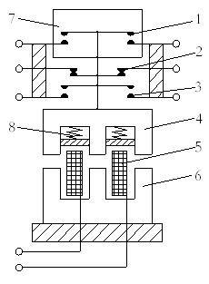
AC contactors can be mainly divided into electromagnetic mechanism, contact system, arc extinguishing device and other components (Yuan & Gao, 2008). Wherein, the electromagnetic mechanism is composed of a coil, a moving iron core (armature iron) and a static iron core; the contact system is composed of a main contact and an auxiliary contact. The specific structure is shown in Figure 1.
When the contactor is working, the coil electrifying causes the static iron core to produce the electromagnetic suction, overcomes the spring reaction force, causes the moving armature to drive the contact mechanism to the static contact movement, realizes the dynamic contact and the static contact closing, completes the contactor closing action, the circuit is connected. When the coil is powered down, the spring reaction force causes the moving armature to drive the contact mechanism to return to its original position, the moving contact and the static contact are separated, the release action is completed, and the circuit is disconnected (Yang & Yang, 2011).
1.Main contact 2. Normally closed auxiliary contact 3. Normally open auxiliary contact 4. Moving iron core 5. Coil 6. Static iron core 7. Arc shield 8. Spring
Figure 1. Structure diagram of AC contactor
2.2. Failure mode of AC contactor
As defined in the national standard GB3187-82, failure means that the product loses the specified function, and the product failure mainly emphasizes the functional state of the product (Leung & Streicher, 2002; Pecht & Dasgupta, 1995). Product failure analysis is to conduct in-depth physical, chemical, and use of the product analysis.
The failure mode of products mainly refers to the external visual failures, cash realisation forms and process rules of products. The failure modes of electrical products are mainly embodied in physical structure failure, performance failure and contact failure. Failures of physical structures, such as structural loosening, part breakage, coil breakage and short circuit, can be determined by physical analysis. The main performance failure phenomena are the increase of closed voltage/current, the decrease of disconnection voltage/current, the increase of contact resistance, the inflexibility of operation and the abnormal time parameters. Contact failure is caused by abnormal electrical parameters of contacts and frequent failures of products due to a combination of factors such as humidity, temperature and vibration.
In this paper, through in-depth study and analysis of the working characteristics of the AC contactor, the contact failure of the contactor is determined as the final failure form to evaluate the reliability of the contactor. The contactor pressure drop value is taken as the static parameter of its reliability determination, and the contactor pressure is observed. The trend of the measured value is measured to determine the reliability of the contactor and the life expectancy.
2.3. Analysis and criterion of contact failure mechanism of AC contactor
There are many reasons for the contactor failure. The failure mechanism analysis of the contactor is to analyze the failure mechanism of the contactor during the service life test. The failure mechanism of contactor can be divided into hard failure mechanism analysis and soft failure mechanism analysis.
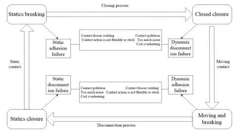
The hard failure of AC contactor is mainly due to the unreliable operation of its closure and disconnection. The hard failure of the contactor will be caused by the influence of the structural parameters of the contactor, the material of the contactor and the external environment factors, and the erosion of the contact surface by the arc during the working process. When the contactor can still complete the function of disconnection and closure, but its contactor voltage drop and open circuit voltage have obvious change trend, contactor soft failure occurs. Figure 2 is a classification of failure modes and hard failure mechanisms of AC contactors in an action cycle.
Figure 2. Failure mode and hard failure accumulation classification diagram
The EMU AC contactor life evaluation test studied in this paper collects the dynamic waveform data of the current and voltage signals of the coil and the contact during the closing and opening process of the contactor, and calculates the arcing time by processing the waveform data obtained by the analysis. And performance parameters such as bounce time to determine the soft failure.
The failure criterion is an important factor in the life assessment and reliability determination test. Different failure criteria in the same test process will make the test conclusions different. Therefore, it is of great significance to determine failure criteria reasonably in the service life evaluation test. In this paper, through the in-depth study and analysis of the failure mode and failure mechanism of the contactor, the following methods are used as the basis for judging the failure of the test product during the test:
- Contact pressure drop of the closed contact Uj>5%Ue;
- Disconnect the voltage between the contacts Uj>90%Ue;
- Contact occurs in fusion or other forms of bonding;
- The contactor coil does not act when the coil is energized.
- Contactor coil does not return when power fails.
- Defective damage to test parts, loose connecting wires and parts.
- Mechanical components are blocked and stuck.
- After the contactor is energized, there is obvious noise.
After testing, the test results of any item are not in conformity with the product standards.
3.1. Hardware system design
The service life simulation system of EMU contactor is the precondition of system function realization. The system composition and realization method directly determine the operation principle and performance of the system.
Figure 3. System composition principle
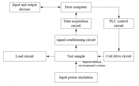
During the simulation test of EMU contactor service life, it is necessary to control the contactor sample to close and disconnect automatically according to the requirement. At the same time, it is necessary to collect the voltage and current of the coil and the main contact during the load on-off process quickly, real-time and accurately. The system is mainly composed of master computer, data acquisition circuit, signal conditioning circuit, coil drive circuit, PLC control circuit, load circuit and input power excitation. As shown in Figure 3.
(1) The main control computer is the control core of the test system. Each part of the control system works according to a certain time sequence and order, and processes, analyzes and judges the collected data information.
(2) The coil drive circuit is mainly composed of a PLC and a solid state relay. The digital I/O port of the PLC is used to control the on/off action of the solid state relay, thereby controlling the contactor to perform the closing and opening operations according to the set operating frequency.
(3) The data acquisition circuit takes the data acquisition board as the core, and carries out real-time and high-speed acquisition of the data obtained by amplitude transformation and filtering of the conditioning circuit.
(4) The coil drive circuit drives the contactor coil to generate electricity and generate electromagnetic attraction force, which drives the contactor movable contact to perform closing and opening operations. The action of the contactor is controlled by the controllable switch, and the controllable switch has a certain load carrying capacity.
(5) Signal conditioning circuit converts the signal that the system needs to collect into the voltage signal acceptable to the data acquisition circuit, and has some filtering function.
3.2. Software system design
Figure 4. Software block diagram
The software of AC contactor service life simulation system for EMU is developed on the basis of LabVIEW environment under Windows operating system. Based on the structure of hardware system and according to different service life simulation test modes, the simulation test of contactor under various service conditions is realized. The software system designed in this paper includes test conditions and parameters setting, failure mechanism discrimination, service life prediction and reliability evaluation. As shown in Figure 4.
Through the mathematical analysis of the reliability of the product, the distribution of product life is found out from the results of mathematical statistics analysis, and the rationality of life distribution can be judged by comparing it with the phenomenon and cause of failure. In this paper, the Weibull distribution method is used to evaluate the service life of the contactor.
4.1. Point estimate of the parameter
In product reliability analysis techniques, the failure distribution type is the failure time distribution function. Many reliability feature quantities are closely related to the failure function density, and the parameter estimation method can be used to solve the reliability feature quantity (Zuo et al., 1999; Marković et al., 2009).
Natural logarithmic form of Weibull function
$\ln [\ln \frac{1}{1-F(t)}]=m\ln t-m\ln \eta $ (1)
where $y=\ln [\ln \frac{1}{1-F(t)}]$, x=lnt, a=m, b=-mlnη, then equation 4.1 is converted to
$y=ax+b$ (2)
Using the method of median rank and fitting straight line, the parameter values of Weibull are calculated by least square estimation of regression coefficients $\overset{\wedge }{\mathop{a}}\,$ and $\overset{\wedge }{\mathop{b}}\,$.
If the error between Equation 4.2 and the test value is the smallest, then it must be satisfied:
$Q=\sum{{{({{y}_{i}}-a{{x}_{i}}-b)}^{2}}}=\min $ (3)
Then parameters a and b should satisfy:
$\left\{ \begin{align} & \frac{\partial Q}{\partial a}=-2\sum\limits_{i=1}^{r}{{{x}_{i}}}({{y}_{i}}-a{{x}_{i}}-b)=0 \\ & \frac{\partial Q}{\partial b}=-2\sum\limits_{i=1}^{r}{{{x}_{i}}}({{y}_{i}}-a{{x}_{i}}-b)=0 \\\end{align} \right.$ (4)
Solutions have to
$\left\{ \begin{align} & a=\frac{n\sum\limits_{i=1}^{r}{x{}_{i}{{y}_{i}}}-\sum\limits_{i=1}^{r}{x{}_{i}}\sum\limits_{i=1}^{r}{{{y}_{i}}}}{r\sum\limits_{i=1}^{r}{x_{i}^{2}-{{(\sum\limits_{i=1}^{r}{x{}_{i}})}^{2}}}} \\ & b=\frac{1}{n}\sum\limits_{i=1}^{r}{{{y}_{i}}-\frac{a}{n}\sum\limits_{i=1}^{r}{x{}_{i}}} \\\end{align} \right.$ (5)
Then
$\left\{ \begin{align} & m=a \\ & \eta ={{e}^{-(\frac{b}{a})}} \\\end{align} \right.$ (6)
A. Interval estimation of parameters
Since the parameter satisfies m=1/σ, η=eμ, the given confidence level is γ, due to
$\gamma =P\left\{ {{\omega }_{(1+\gamma )/2}}\le \frac{\overset{\wedge }{\mathop{\sigma }}\,}{\sigma }\le {{\omega }_{(1-\gamma )/2}} \right\}=P\left\{ {{\omega }_{(1+\gamma )/2}}/\overset{\wedge }{\mathop{\sigma }}\,\le m\le {{\omega }_{(1-\gamma )/2}}/\overset{\wedge }{\mathop{\sigma }}\, \right\}$ (7)
Therefore, the confidence interval for the parameter m is
$[{{\omega }_{(1-\gamma )/2}}/\overset{\wedge }{\mathop{\sigma ,}}\,{{\omega }_{(1+\gamma )/2}}/\overset{\wedge }{\mathop{\sigma }}\,]$ (8)
Similarly, for a given confidence level of γ, using the confidence interval of the parameter $\mu $, the confidence interval for the confidence level of the parameter η is γ.
$[\exp (\overset{\wedge }{\mathop{\mu }}\,-\overset{\wedge }{\mathop{\sigma }}\,{{\upsilon }_{(1+\gamma )/2}}),\exp (\overset{\wedge }{\mathop{\mu }}\,-\overset{\wedge }{\mathop{\sigma }}\,{{\upsilon }_{(1-\gamma )/2}})]$ (9)
Where
$\overset{\wedge }{\mathop{\sigma }}\,=\underset{i=1}{\overset{r}{\mathop{\sum }}}\,C(n,r,i)\ln {{t}_{i}},\overset{\wedge }{\mathop{\omega }}\,=\underset{i=1}{\overset{r}{\mathop{\sum }}}\,D(n,r,i)\ln {{t}_{i}}$.
4.2. One-sided confidence limit for reliable life and reliability
When the product is subject to the Weibull distribution, the corresponding reliable lifetime for a given credibility is:
${{t}_{R}}=\eta {{(-\ln R)}^{1/m}}=\eta {{(-\ln R)}^{\sigma }}=\exp [\mu +\sigma \ln (-\ln R)]$ (10)
let
$V(R)=\frac{\overset{\wedge }{\mathop{\mu }}\,-\ln {{t}_{R}}}{\overset{\wedge }{\mathop{\sigma }}\,}=\frac{\overset{\wedge }{\mathop{\mu }}\,-\mu -\sigma \ln (-\ln R)}{\overset{\wedge }{\mathop{\sigma }}\,}=\frac{\overset{\wedge }{\mathop{\mu }}\,-\mu }{\overset{\wedge }{\mathop{\sigma }}\,}-\frac{\sigma }{\overset{\wedge }{\mathop{\sigma }}\,}\ln (-\ln R)$ (11)
It can be seen that the random variable V(R) is the axial pivot of the reliable life tR, and the standard random distribution of n random numbers U1,U2,…Un is generated on the computer, where n is the sample size of the fixed censored life test, and the simulation is performed by the Monte-Carlo method. The distribution of the axis pivot amount V(R), while obtaining the confidence level of its tR confidence level is γ:
${{t}_{RL}}=\exp [\overset{\wedge }{\mathop{\mu }}\,-\overset{\wedge }{\mathop{\sigma }}\,{{\omega }_{1-r}}(R)]$ (12)
For a given time td, let xd=lntd, therefore have
$\begin{align} & \ln [-\ln \overset{\wedge }{\mathop{R}}\,({{t}_{d}})]=\frac{{{x}_{d}}-\overset{\wedge }{\mathop{\mu }}\,}{\overset{\wedge }{\mathop{\sigma }}\,}=\frac{\sigma }{\overset{\wedge }{\mathop{\sigma }}\,}(\frac{{{x}_{d}}-\mu }{\sigma }-\frac{\overset{\wedge }{\mathop{\mu }}\,-\mu }{\sigma }) \\ & =\{\frac{\overset{\wedge }{\mathop{\mu }}\,-\mu }{\overset{\wedge }{\mathop{\sigma }}\,}-\frac{\sigma }{\overset{\wedge }{\mathop{\sigma }}\,}\ln [-\ln R({{t}_{d}})]\}=-{{V}_{[R({{t}_{d}})]}} \end{align}$ (13)
Obtained by the above formula
${{V}_{R({{t}_{0}})}}=\frac{\overset{\wedge }{\mathop{\mu }}\,-{{x}_{d}}}{\overset{\wedge }{\mathop{\sigma }}\,}$ (14)
When the significant level is 1-α, use the quantile table of V1-p to find the values of two VR(td) adjacent to V1-p,1-α, and then use linear interpolation to find the RL(t) corresponding to VL(td).
In order to verify the feasibility of the EMU AC contactor life evaluation method proposed in this paper, the service life evaluation simulation experiment was carried out on the EMU AC contactor by using the built system, and the life assessment analysis was carried out.
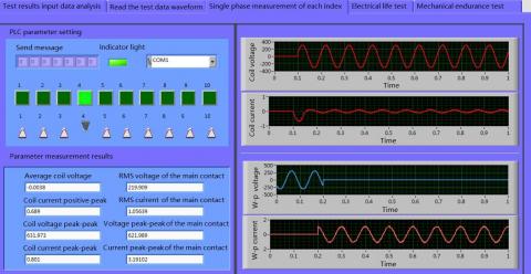
The contactor model used in the experiment is LC1-D 0910. Figure 5 shows the AC contactor main contact and coil voltage and current waveform signal acquisition. Table 1 shows the reliability life prediction distribution table of the high-speed motor AC contactor.
Through the analysis of the experimental data, it can be seen that the reliability of the AC contactor of EMU can approach 100% for 100 000 times, almost without failure. The reliability of the action is more than 60% in the one million time. With the increase of the number of actions, the reliability decreases quickly. After 2 million actions, only 10 may be left at work, almost all of them fail. Take the frequent action of the system door control and air conditioning 100 times a day as an example, to ensure the reliability of more than 60%, it can work for 10,000 days.
Figure 5. AC contactor main contact and coil waveform measurement results
Table 1. EMU AC contactor reliability life prediction distribution table
|
Serial number |
Life h |
Reliability |
Serial number |
Life h |
Reliability |
|
1 |
0 |
100.00% |
17 |
2304000 |
7.39% |
|
2 |
144000 |
99.18% |
18 |
2448000 |
5.22% |
|
3 |
288000 |
96.57% |
19 |
2592000 |
3.60% |
|
4 |
432000 |
92.23% |
20 |
2736000 |
2.42% |
|
5 |
576000 |
86.34% |
21 |
2880000 |
1.60% |
|
6 |
720000 |
79.19% |
22 |
3024000 |
1.03% |
|
7 |
864000 |
71.14% |
23 |
3168000 |
0.65% |
|
8 |
1008000 |
62.57% |
24 |
3312000 |
0.40% |
|
9 |
1152000 |
53.88% |
25 |
3456000 |
0.24% |
|
10 |
1296000 |
45.40% |
26 |
3600000 |
0.14% |
|
11 |
1440000 |
37.44% |
27 |
2304000 |
7.39% |
|
12 |
1584000 |
30.20% |
28 |
3456000 |
0.24% |
|
13 |
1728000 |
23.83% |
29 |
3600000 |
0.14% |
|
14 |
1872000 |
18.40% |
30 |
3744000 |
0.08% |
|
15 |
2016000 |
13.89% |
31 |
4176000 |
0.01% |
|
16 |
2160000 |
10.25% |
32 |
4464000 |
0.00% |
Aiming at the requirement of correctly predicting the service life of AC contactor in EMU operation and maintenance, this paper presents a simulation method for the service life of AC contactor in EMU. Firstly, the failure mechanism of AC contactor of EMU is studied and analyzed. Then the service life simulation platform of AC contactor of EMU is built. Then the reliability evaluation method of contactor based on Weibull distribution method is studied. Finally, the feasibility of the proposed method is verified by experiments.
Leung C., Streicher E. (2002). Material transfer in dynamic welding of Ag and Ag/SnO2 contact material. Proceedings of the 48th IEEE Holm Conference on Electrical Contacts, pp. 21-28. https://doi.org/10.1109/HOLM.2002.1040818
Marković D., Jukić D., Benšić M. (2009). Nonlinear weighted least squares estimation of a three.parameter weibull density with a nonparametric start. Journal of Computational and Applied Mathematics, Vol. 288, No. 1, pp. 304-312. https://doi.org/10.1016/j.cam.2008.09.025
Pecht M., Dasgupta A. (1995). Physics.of.failure: An Approach to Reliable Product Development. Journal of the Institute of Environmental Sciences, No. 38, pp. 30-34. https://doi.org/ 10.1109/IRWS.1995.493566
Schoepf T. J., Boudina A., Rowlands R. D., Repp B. T. (2009). Pre.conditioning automotive relay contacts to increase their resistance to dynamic welding. IEICE Transactions on Electronics, Vol. 90C, No. 7, pp. 1441-1447. https://doi.org/10.1093/ietele/e90-c.7.1441
Tang J., Su T. S. (2008). Estimating failure time distribution and its parameters based on intermediate data from a wiener degradation model. Naval Research Logistics, Vol. 55, No. 3, pp. 265-276. https://doi.org/10.1002/nav.20280
Yang Y., Yang X. (2011). Electronic equipment reliability test. Digital Communication. Vol. 38, No. 6, pp. 66-69. https://doi.org/10.3969/j.issn.1001-3824.2011.06.018
Yuan X. Q., Gao P. (2008). Talking about the structure, application and development of AC contactor. Electrical Manufacturing, Vol. 2008, No. 1, pp. 34-36. https://doi.org/10.3969/j.issn.1673-5471.2008.01.006
Zuo M. J., Jiang R. Y., Richard C. M. Yam. (1999). Approaches for reliability modeling of continuous.state devices. IEEE Transactions on Reliability, Vol. 48, No. 1, pp. 9-18. https://doi.org/10.1109/24.765922