OPEN ACCESS
Interconnected power system is the complex system which is having the stability maintenance as the important factor to be in the synchronism with respect to all generators connected to the system. To maintain the synchronism among all generators and loads that are interconnected, the stability of each individual machine and also the stability of interconnected machines have gained importance. Damping torque adjustment or sufficient supply of the damping torque to the synchronous machine which will increase the stability of the system is done by applying the power system stabilizer. This paper presents an attempt to design the power system stabilizer using the Firefly search Algorithm to increase the stability of the three machine nine bus system which is an interconnected system of hydro thermal generators. The enhanced stability of the multi machine system was compared with Genetic search Algorithm stabilizer. It is evident that the enhancement of the stability of the multi machine system is achieved by getting the stable Eigen values. It is also observed that the responses of relative variations of interconnected states of the multi machine system with under the nonlinearity condition. The responses of the system with firefly based power system stabilizer are settled at faster rate for the normal case and also for the contingency cases. The results are compared with the genetic algorithm stabilizer. In the Pseudo Spectrum observation the stable poles of the system are evident for the improved stability of the multi machine system.
power system stabilizer (PSS), firefly algorithm (FFY), genetic algorithm (GA), pseudo spectrum analysis, contingency
The practical power system comprises of number of generators and number of loads connected and makes the system as complex system. The stable operation of the alternator has gained more importance in the interconnected complex power system. For designing the system which is more effective and economical with more unit sizes and high per unit reactance in the design of generation and transmission equipment designs, it is advisable to design the compensating devices which will provide the compensating signal required to compensate the reduction in the stability margins. Dil and Silva, (2011) Fleming et al., (1981) Gurrala & Sen, (2010) and Moussa & Yu, (1972; 1974) have discussed about the problem of stability improvement of multi machine interconnected system and efforts made to enhance the dynamic stability of the interconnected power system and the analysis can be done by using Pseudo spectra.
The design of conventional regulators which will control the voltage and also high speed excitation systems with high ceiling voltage are used to increase the stability. But these regulators and excitation systems will not provide the sufficient damping torque which can able to effect the stability improvement. In some cases the stable system may operate with negative damping characteristics. Goldberg, (1989) Moussa & Yu, Hasan et al. (1991) and Babaei et al. (2009), have discussed about the voltage regulators which will improves the situation by supplying the negative damping and it may lead to result the instability of the system which is an undesirable condition and this may be overcome by using artificial intelligent techniques.
During the low-frequency dynamics, the induced current in the damper windings is very less so that it can be negligible. With this reason the effect of the damper windings are ignored in the modeling of the system. The direct axis and quadrature axis armature windings of the alternators and their Eigen modes will not affect the low-frequency dynamics so that they can be explained by the algebraic equations. Yu et al. (1970; 1971; 1972), Pandeno et al. (1968), have explained the circuit of the field winding of the alternator is by the differential equation, because of its low Eigen mode frequency and also directly connected to the excitation system to which the additional excitation control is applied.
Adbennonr & Lee (1996), Anderson (1971), have analyzed the multi machine power system is a highly complex system contains nonlinear with more number of generating plants and also different types of plants like hydro, thermal plants. Xin-She Yang, has proposed many nature inspired algorithms and these algorithms are useful in the design of PSS. The condition of operation of various types of plants with different loading conditions will make the combined multi machine system as nonlinear system operating with continuously varying operating conditions. Padiyar and Kundur have explained the concepts of PSS by using by using the block diagrams.
Mahabuba & Khan (2013), Humpage et al., (1973) and Yu et al., have proposed methodologies to get the improved dynamic performance of the multi machine interconnected system it is very much essential to use a supplementary stabilizing signals which will improve the stability by increasing damping torque of each synchronous machine and further it improves the interconnected system stability also. From the past few years many approaches are came across in the literature for providing the damping torque required for the enhancement of the dynamic stability. The power system stabilizer contains a lead/lag compensator and gain will use the speed and/or power as input signal to give the supplementary stabilizing signal can be designed and applied. The parameters of the stabilizer were designed by applying different methods like to employ a linear optimal stabilizer by using the concept of linear optimal regulators etc.
From the literature the algorithms are proposed which stabilizes based on the search algorithms like GA, ANT colony, PSO, fuzzy logic approaches etc. The PSS parameter search algorithms genetic algorithm, firefly algorithms are used to find the best PSS parameters which will ensure the stability of a multi machine power system. The genetic algorithm uses the genetic operators to search the optimal PSS parameters. In this proposed work the Firefly search algorithm is used to tune the PSS parameters. Since the considered interconnected hydro thermal multi machine system is complex which replica of the system operating with various operating conditions, the designed PSS must ensure the improvement in the stability of individual and also the inter machine stability. Andreoiu & Bhattacharya (2002) have proposed the Lyapunov’s method using the genetic algorithm to tune the PSS.
Schleif et al., (1969) have explained the controlling of rotating exciters of the synchronous generators. The small signal stability is the predominant factor and that must be maintained in the interconnected power system in between each alternator. The modern power system will undergo frequently the problem of low frequency oscillations and the problem of voltage instability that are caused by swinging rotor of the synchronous generator and contingencies in the interconnected power system. The contingency analysis is extensively used to forecast the effect of abnormal conditions, like line outages, equipment failure related to either generator or transformer and the over loading conditions. The line outages will cause more severe problems in the modern power system such as over loading of other lines in the system or results the abnormal system voltages.
Contingency analysis is one of the important procedures in the energy management system (EMS), and it helps to identify the most unfavorable element in the interconnected power system. In this inter connected multi machine system, one line is identified and the analysis is done with that line outage. Asija et al., (2015) have discussed about the problem of contingency. It is very much necessary to enhance the stability of the system even with the contingency problem. In the literature it presents the enhanced stability of power system by damping out the low frequency oscillations, by controlling the variations in voltage and real and reactive power flows in multi machine system without contingencies. A new methodology is proposed in this article to determine parameters in the power system stabilizer for three machine nine bus system, by using the design and application of firefly algorithm based stabilizer.
The results are analyzed by using the pseudo spectrum analysis and also by analyzing the inter machine stability with and without contingency. It is evident that the proposed stabilizer ensures the improved stability of the multi machine system for normal and contingency cases.
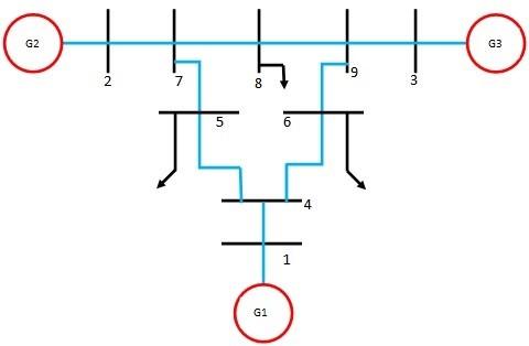
The configuration of the multi-machine system considered is the three machine nine bus system which comprises of simultaneous and synchronous operation of one hydro generator and two thermal generators.
The single line diagram of the interconnected hydro thermal multi machine system is shown in Figure 1. The block diagram model of this ‘i’ number machine system with the voltage regulator, exciter is shown in Figure 2. The linearised incremental model of this system is considered for the analysis of dynamic stability.
Figure 1. Line diagram of hydro thermal interconnected system
For the modeling of the tested system in the form of state space equation from the standard system of three machine connected to nine buses the following procedure is followed
Formulate the Y-Bus matrix of multi machine system by direct inspection method from the standard network data of the three machine nine bus system.
Determine the Y-reduced matrix which is appropriate to the size of the number of machines of the tested system. In this tested system there are three numbers of generators exists so that the formulated Y- bus can be reduced in to 3X3 matrix.
Obtain the load flow results by using the Newton Rapson method.
Table 1. Line data of 3 machine 9 bus system
|
From Bus |
To Bus |
R (pu) |
X (pu) |
B (pu) |
|
1 |
4 |
0.0 |
0.0576 |
0.0 |
|
4 |
5 |
0.01 |
0.085 |
0.176 |
|
4 |
6 |
0.017 |
0.092 |
0.158 |
|
6 |
9 |
0.039 |
0.17 |
0.358 |
|
5 |
7 |
0.032 |
0.161 |
0.306 |
|
2 |
7 |
0.0 |
0.0625 |
0.0 |
|
7 |
8 |
0.0085 |
0.072 |
0.149 |
|
8 |
9 |
0.0119 |
0.1008 |
0.209 |
|
3 |
9 |
0.0 |
0.0586 |
0.0 |
Table 2. Machine data of three machine system
|
Parameters |
Machine 1 (Hydro) |
Machine 2 (Thermal) |
Machine 3 (Thermal) |
|
H(secs) |
23.64 |
6.4 |
3.01 |
|
Xd (pu) |
0.146 |
0.8958 |
1.3125 |
|
Xd|(pu) |
0.0608 |
0.1198 |
0.1813 |
|
Xq(pu) |
0.0969 |
0.8645 |
1.2578 |
|
Xq|(pu) |
0.0969 |
0.1969 |
0.25 |
|
Tdo|(pu) |
8.96 |
6.0 |
5.89 |
|
Tqo|(pu) |
0.31 |
0.535 |
0.6 |
Table 3. Load flow results for 3 machine 9 bus system
|
S.NO |
Bus type |
Voltage (pu) |
Delta |
PG (pu) |
QG (pu) |
-PL (pu) |
-QL (pu) |
|
1 |
Swing |
1.0400 |
0 |
0.716 |
0.2700 |
- |
- |
|
2 |
P-V |
1.0250 |
9.3 |
1.630 |
0.0670 |
- |
- |
|
3 |
P-V |
1.0250 |
4.7 |
0.850 |
-0.1090 |
- |
- |
|
4 |
P-Q |
1.0260 |
-2.2 |
- |
- |
- |
- |
|
5 |
P-Q |
0.9960 |
-4.0 |
- |
- |
1.25 |
0.5 |
|
6 |
P-Q |
1.0130 |
-3.7 |
- |
- |
0.90 |
0.3 |
|
7 |
P-Q |
1.0260 |
3.7 |
- |
- |
- |
- |
|
8 |
P-Q |
1.0160 |
0.7 |
- |
- |
1.00 |
0.3 |
|
9 |
P-Q |
1.0320 |
2.0 |
- |
- |
- |
- |
Derive the initial conditions from the obtained load flow results and the Y-reduced matrices.
Determine the K- constant matrices from the initial conditions. For the multi machine system the ‘K’ constants are obtained as the matrices which are having the size as the number of machines. In this tested system the sizes of the ‘K’ constant matrices are 3X3.
By following the procedure mentioned above and by using the load flow analysis the ‘K’ constant matrices of six in number with the dimensions of 3X3 are derived as
$K_{1}=\left[\begin{array}{ccc}{-1.2666} & {0.7526} & {0.5141} \\ {0.2109} & {1.3991} & {-1.6100} \\ {0.2876} & {-1.4817} & {1.1941}\end{array}\right] K_{2}=\left[\begin{array}{ccc}{0.4924} & {2.2572} & {1.8379} \\ {-2.2952} & {5.0584} & {-1.8453} \\ {-2.0490} & {-1.4591} & {4.2565}\end{array}\right]$
$K_{3}=\left[\begin{array}{ccc}{0.8030} & {-27.4920} & {-10.7108} \\ {-0.8432} & {0.1981} & {-0.4568} \\ {-0.4345} & {-0.3444} & {0.1465}\end{array}\right] K_{4}=\left[\begin{array}{ccc}{0.2662} & {-0.1243} & {-0.1419} \\ {1.3513} & {0.1238} & {-1.4750} \\ {1.4986} & {-2.3899} & {0.8913}\end{array}\right]$
$K_{5}=\left[\begin{array}{ccc}{-0.1972} & {0.0930} & {0.1042} \\ {-0.5166} & {0.4888} & {0.0278} \\ {-0.5711} & {0.1981} & {0.3730}\end{array}\right] K_{6}=\left[\begin{array}{ccc}{0.8219} & {0.0388} & {0.0771} \\ {-0.3665} & {0.4287} & {0.2527} \\ {-0.2426} & {0.4781} & {0.1843}\end{array}\right]$
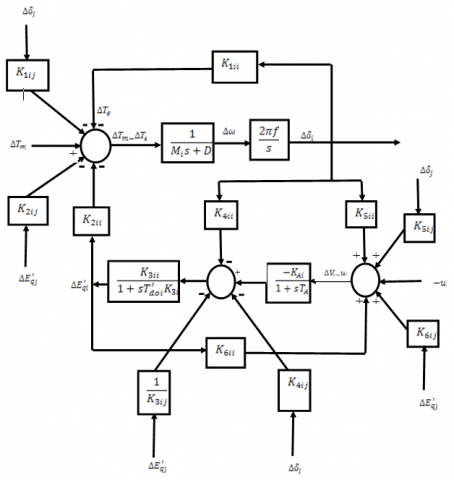
Figure 2. Linearized model of synchronous machine with an exciter
The linearised model equations of the given linearised incremental model of machine shown in Fig.2 with an exciter are written in the form of state space equations which results the state matrix ‘Am’, the states that are considered for the analysis are written in the form of:
$\overline{x}_{m}=A_{m} x_{m}+B_{m} u$ (1)
The state vector matrix ‘xm’ includes the dominant states of every machine of the interconnected multi machine system as Δωi, Δdi, Δeq’i, ΔeFDi, of each generator where i=1, 2,3. From the block diagram shown, the equations for the twelve states of three machines are written as:
$\Delta \omega_{i}=\frac{1}{M_{i} s+D_{i}}\left(\Delta T_{m i}-\Delta T_{e i}\right)$ (2)
$\Delta \delta_{i}=\frac{2 \pi f}{s} \Delta \omega_{i}$ (3)
$\Delta E_{q i}^{\prime}=\left[\frac{K_{3 i i}}{1+s T_{d 0}}\right]\left[-K_{4 i} \Delta \delta_{i}-K_{4 i j} \Delta \delta_{j}-\left[\frac{1}{K_{3 j}}\right] \Delta E_{q j}+\Delta e_{F D i}\right]$ (4)
$\Delta e_{F D i}=\frac{-K_{A}}{1+s T_{A}}\left(\Delta V_{i}-U_{i}\right)$ (5)
The transfer function block diagram shown in Fig.2 of the multi machine system explains the dynamics of ‘i’ number of machines in a multi-machine interconnected system.
By using the 'K' constant matrices and the state equations derived from the block diagram of the multi machine system, the system matrix 'Am' and the control matrix 'Bm' are derived.
To analyze the process of improvement stability of the interconnected multi machine system, a standard three generator nine bus system was considered. It consists of one hydro generator and two thermal generators. The tested system can be written in the form of state space as equation.
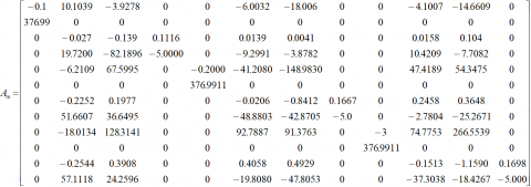
The system matrix 'Am' without PSS is obtained as
$B_{m}=\left[\begin{array}{cccccccccccc}{0} & {0} & {0} & {100} & {0} & {0} & {0} & {0} & {0} & {0} & {0} & {0} \\ {0} & {0} & {0} & {0} & {0} & {0} & {0} & {100} & {0} & {0} & {0} & {0} \\ {0} & {0} & {0} & {0} & {0} & {0} & {0} & {0} & {0} & {0} & {0} & {100}\end{array}\right]^{T}$
From the above system, the state matrix ‘Am’ it is observed that the Eigen values of this open loop system are obtained as unstable poles that is which lies on the right hand side of the complex plane as mentioned in the table.5 which is unstable region. This shows the essential need of the supplementary stabilizing signal. As like in the single machine connected to the infinite bus system, the stabilizer which stabilizes the SMIB can be able to stabilize the multi machine system also.
To maintain the multi machine system as an ensured stable system the problem of stabilization can be solved by designing the PSS and application of PSS to all the three machines. For getting the stable Eigen values for the tested system, the parameters of power system stabilizer is tuned by using the genetic algorithm and firefly algorithms. For formulating the problem by using search algorithms, new state equations are written, hence the size of the state matrix ‘Am’ is increased from 12 X 12 to 15 X 15. By considering a lead circuit and the gain blocks as the structure of the stabilizer, the equation of transfer function of the stabilizer is written as:
$G_{p i}(s)=\frac{K_{s i}\left(1+s T_{1 i}\right)}{\left(1+s T_{2 i}\right)}$ (6)
With the design and application of power system stabilizer, the new state equations are added and the system is written in the state space form with increase in the size of system state matrix 'Ak' with 15x15. The new state equation with the power system stabilizer is written as
$\dot{x}_{m p}=A_{k} x_{m p}+B_{m p} u$ (7)
The required values of the PSS parameters gains and time constants are Ksi, T1i and T2i; i=1, 2, 3 are searched by using proposed method and genetic algorithm approach. The obtained results are applied to the matrix Ak to check the locations of the Eigen values on the complex plane. For searching the PSS parameters with Genetic search Algorithm approach the population size is selected as 200 and the optimum result was obtained for 1000 number of generations. For selection of stabilizer parameters with the Firefly search Algorithm approach the optimum stabilizer parameters are obtained for 200 generations and 50 population size. The designed parameters of PSS with Fire fly and genetic algorithm are tabulated. The stability of the tested multi machine system for several conditions like without any controller, with stabilizer tuned by genetic algorithm and firefly algorithm are tested and tabulated. The enhanced stability by the application of PSS tuned by genetic algorithm and firefly algorithms are also determined and shown in table.5.
The genetic search algorithm is used in this work to determine the parameters of PSS which can ensure the stability. A set of points to be searched is selected and used initially is called as population and is a set of chromosomes. The initial population is applied through the operators of GA for further generation of a new population. Merely the fittest organisms will used for reproduction, the weakest organisms will not be used for the next step. The global optimum result is obtained by following the said procedure up to the convergence point. In the process, the genetic operators: reproduction, crossover and mutation are applied to get the new set of parameters of PSS. Evaluation and Genetic Operation are performed repeatedly until the convergence is achieved.
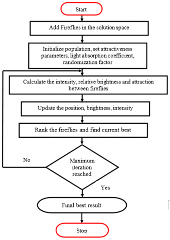
The flash signal of a firefly is acting like a signal to attract the following fireflies. The attraction between the fireflies is depending on the brightness of the fireflies. If the brightness of one firefly is more, the firefly with less brightness is attracted by the first one having more brightness. A global optimization problem can be formulated by starting from the local optimized solution from various starting points. The objective function is designed such that it will determine the brightness of the firefly. The iterative solution of a mathematical optimization problem by applying the constraints will give the best parameters of the power system stabilizer. These parameters are giving the stable Eigen poles for the multi machine system. The process of firefly algorithm is explained in the flow chart shown in the Fig.3
To attain this desirable condition the approach followed to find the parameters Ksi and T1i and T2i of the power system stabilizer for i=1,2,3 is proposed as to minimize the objective function proposed by Rashidi et al., (2003) shown in the following equation.
J = maxRe(αi,k), k = 1 ,2,3, ,i = 1 ,2,3
Where αk,i is the kth closed-loop eigen value of the ith plant. The designed parameters of the desired stabilizer Ksi, T1i and T2i by applying the firefly search algorithm will gives the more stabilized poles for the multi machine system. The poles which are getting after application of the design of PSS is evident for the more stabilized relative variation of the hydro thermal interconnected system. The problem of optimization is resolved by using genetic search algorithms and firefly algorithms.
Table 4. Designed controller (PSS) parameters
|
GA PSS |
KS1=-0.93358 |
T11=-88.54158 |
T12=0.00026 |
|
KS2=163.3920 |
T12=0.0076950 |
T22=1126.62 |
|
|
KS3=193.8942 |
T13=-0.008603 |
T23=2298.87 |
|
|
FFY PSS |
KS1=-0.9353 |
T11=-88.50 |
T12=0.00029 |
|
KS2=163.3316 |
T12=0.00716 |
T22=1126.32 |
|
|
KS3=193.1943 |
T13=-0.00875 |
T23=2298.07 |
Figure 3. Firefly search algorithm flowchart
From the table 5 it is observed that the Eigen values without any controller are evident for the un-stability of the system. The poles for the application of PSS and the application of PSS with Firefly are showing the improved stability of the interconnected multi machine system.
Table 5. Eigen values for the test system without and with PSS
|
Without any controller |
With GA PSS |
With FFY PSS |
|
-0.0060 + 2.1836i |
-3.3778 + 0.0002i |
-3.7223 + 0.0005i |
|
-0.0060 – 2.1836i |
-0.0002 + 0.0043i |
-0.0019 + 0.0043i |
|
0.8769 + 0.0003i |
-0.0002 – 0.0043i |
-0.0019 – 0.0043i |
|
-0.8879 + 0.0003i |
-0.0011 + 0.0041i |
-0.0021 + 0.0042i |
|
-0.0240 + 0.0566i |
-0.0011 – 0.0041i |
-0.0021 – 0.0042i |
|
-0.0240 – 0.0566i |
-0.0003 + 0.0021i |
-0.0007 + 0.0021i |
|
-0.0700 + 0.0011i |
-0.0003 – 0.0021i |
-0.0007 – 0.0021i |
|
-0.0253 + 0.0244i |
-0.0005 + 0.0001i |
-0.0060 + 0.0001i |
|
-0.0253 – 0.0244i |
-0.0005 – 0.0001i |
-0.0060 – 0.0001i |
|
0.0148 + 0.0005i |
-0.0002 + 0.0001i |
-0.0021 + 0.0001i |
|
0.0012 + 0.0007i |
-0.0002 – 0.0001i |
-0.0021 – 0.0001i |
|
-0.0008 + 0.0000i |
-0.0006 + 0.0002i |
-0.0008 + 0.0004i |
|
----- |
-0.0006 – 0.0002i |
-0.0008 – 0.0004i |
|
----- |
-0.0031 + 0.00001i |
-0.0017 + 0.0003i |
|
----- |
-0.0031 + 0.00001i |
-0.0017 – 0.00003i |
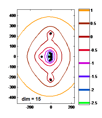
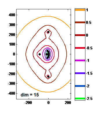
The pseudo spectrum analysis was done for the Eigen values of different cases and it is observed that the Eigen values for without controller and with controllers cases. The Eigen values are lying in the left hand side for the unstable system and lying on the right hand side for the stable system with respect to the complex plane. It is also observed that the Eigen values of the design and application of PSS with FFY case are lying on more stable side of the S-plane when compared with the application of PSS alone. Hence the proposed method of coordinated deign and application of PSS is resulting more stability for the tested system.
By analyzing the Eigen values obtained by pseudo spectrum analysis the proposed methodology to design the PSS will give the stable poles which lies on the left hand side of the imaginary axis.
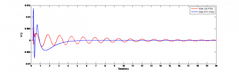
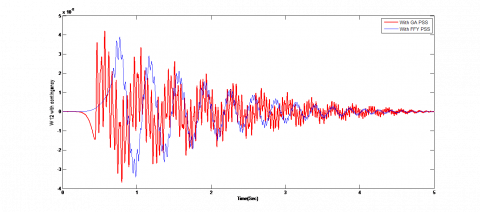
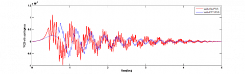
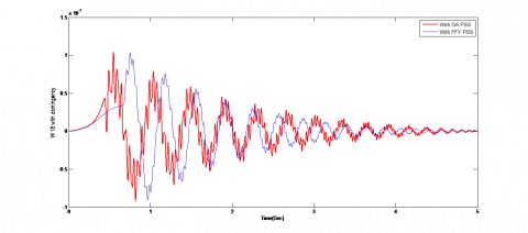
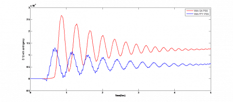
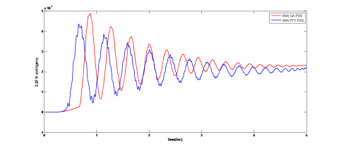
To check the maintenance of inter machine stability is it very important to see that the variations in the speed deviations between the set of machines that is between 1-2; 2-3 and 1-3. If the speed variations between these mentioned set of machines settled at zero position as fast as possible it can be concluded that there is an inter machine stability is maintained effectively. So, by applying the step disturbances to the system the differences in the speed of multi machine system are plotted.
Figure 4. Response of ω12 with GA PSS and FFY PSS
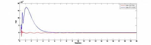
Figure 5. Response of ω23 with GA PSS and FFY PSS
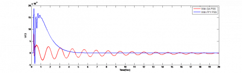
Figure 6. Response of ω13 with GA PSS and FFY PSS
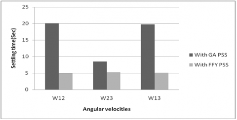
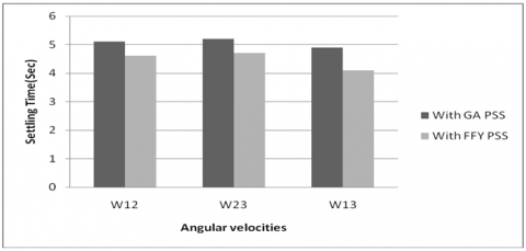
Figure 7. Settling Times of the Responses of ω12, ω23, ω13 with GA and FFY PSS
By the observation of the parameters like the maximum overshoot, undershoot and the settling times of the responses, it should be noted that the designed stabilizer is having the considerable effect on the stability improvement. However, there are more oscillations in the differences of angular velocities and also in the load angles.
Due to the contingencies in the power system, the stability may get affected and the need of the stabilizer design is necessary to keep the system in the stable operation of the interconnected multi machine power system. It is proposed the best parameters of the stabilizer by using the firefly search algorithms. The multi machine system is analyzed by creating the problem of contingency. The considered aspect of stability is tested and the stabilizer is designed for the alternators. The stable pseudo spectrum analysis using the Eigen values shows the proposed stabilizer gives the enhanced stability of the system for the step responses of each state of the three machine nine bus system.
Power system stability is stated that the property of the system to remain in the state of equilibrium under the normal conditions and regain its state of equilibrium after subjected to disturbances like contingency problems. In evaluation of stability, observe the performance of the power system under transient disturbances. If the disturbances are small like load changes takes place continuously for that type of disturbance system changes its operating conditions itself. Similarly system must be survived for large disturbances also like fault occurring in transmission line, loss of generating unit or load. System response always depends on the equipment in the power system. For example voltage variations in the power system will initiate both transmission line and generator speed variations will initiate prime mover governors.
Contingencies are categorized into two types, one of those is power outages and the other one is the system outage. The Power outages are mainly due to the loss of generating units and due to sudden variations in the load. The failure of the generating units will cause the small disturbances in the power system. The power line outages, also called control blackouts or the system outages are mainly due to the outage of transmission lines and failure of the transformer. The system outages are most frequently occurring contingency problems in the interconnected systems. These will cause the voltage instability problems in the multi machine power system.
So, in order to filter out the worst contingency problems, the ranking is allotted based on the observation of the performance indexes of the system such as continuous power flow, voltage profile of each bus or the maximum loading parameter. In this proposal, the maximum loading parameter is considered as the performance index to identify the worst contingency problem. Based on past researches, contingency analysis is consuming more time for the large power systems. To reduce the time some new techniques are proposed in the literature such as Newton Raphson method, fast decoupled method, and the algorithms for automatic contingency analysis or Power system analysis toolbox. It is observed that by doing the contingency analysis the multi machine system is to be treated as operating at new operating condition and the analysis to be done for finding its stability state of operation.
For the tested multi machine system which is three machine nine bus system, the contingency analysis is done by calculating the maximum loading parameter for all possible lines by the observation of continuous power flows.
From the obtained results the worst case of contingency based on maximum loading parameter is determined and tabulated.
Table 6. Severity ranking for 3 machine-9bus system
|
Order of severity |
Line |
Maximum loading parameter |
|
1 |
4-5 |
0.8900 |
|
2 |
5-7 |
1.1086 |
|
3 |
7-8 |
1.1698 |
|
4 |
6-9 |
1.1764 |
|
5 |
8-9 |
1.4865 |
|
6 |
4-6 |
1.6617 |
From the contingency analysis it is observed that the line connected between the buses 4 and 6 is getting the maximum loading parameter. Based on the contingency analysis the line between the 4 and 6 buses is removed and the system with this contingency problem is considered as the tested system.
After removal of the line 4-6 the load flows in the three machine nine bus system are observed that the complete modeling of the multi machine system is changed. From the load flow results and from the data of the three synchronous machines the initial conditions are calculated. From the initial conditions by following the procedure, the newly obtained ‘K’ constants are determined to form the new system matrix ‘AC’ with contingency. By using these ‘K’ constants and the state equations of the multi machine system mentioned the system matrix ‘AC’ with contingency is obtained.
After careful observation of the Eigen values of the above system, it is noted that some of the Eigen values are located on the right hand side of the complex plane. To shift the unstable Eigen values on to the stable side of the complex plane the need of the supplementary stabilizing signal is very much required. Hence this condition motivates for the design and application of the stabilizer to the system. To control all the states of the multi machine system with the help of the control matrix ‘BC’ mentioned above the controller which will ensure the stable settlement of the inter machine stability aspect is designed and applied. With the design and application PSS, new state equations are added and the system is written in the state space form with increase in the size of system state matrix ‘AP’ with 15x15. The newly formed state equation with the inclusion of the power system stabilizer is written as
$\dot{x}_{C P}=A_{C P} x+B C_{P} u$ (9)
By considering a lead circuit and the stabilizer gain blocks as mentioned in the stabilizer structure, the equation of transfer function of the stabilizer is written as:
$G_{p i}(s)=\frac{K_{s i}\left(1+s T_{1 i}\right)}{\left(1+s T_{2 j}\right)}$
The unknown parameters of the power system stabilizer, stabilizer gain and time constants are Ksi, T1i and T2i; i=1, 2, 3 are searched by using proposed method and the genetic search Algorithm approaches. The obtained results are applied to the matrix AP for checking the locations of the newly obtained Eigen values on the complex plane. For searching the PSS parameters with Genetic Algorithm approach the population size is selected as 200 and the optimum result was obtained for 1000 number of generations. For selection of stabilizer parameters with the Firefly Algorithm approach the optimum stabilizer parameters are obtained for 200 generations and 50 population size. The designed parameters of the stabilizer with Firefly and genetic algorithm are tabulated. The washout time constant of the PSS was considered as 2 sec.
The stability of the tested inter connected system for the conditions as without any controller and with the stabilizer tuned by genetic algorithm and firefly algorithms are tabulated. The Eigen values of the enhanced stability by the application of PSS tuned by genetic algorithm and firefly algorithms are also determined.
Table 7. Designed controller (PSS) parameters under contingency condition
|
GA PSS |
KS1=0.0555 |
T11=0.1412 |
T12=1.0945 |
|
KS2=-0.0371 |
T12=-0.4331 |
T22=37.1152 |
|
|
KS3=-0.0457 |
T13=0.5725 |
T23=2.4456 |
|
|
FFY PSS |
KS1=0.05 |
T11=0.15 |
T12=1.0962 |
|
KS2=-0.0371 |
T12=-0.4684 |
T22=37.1001 |
|
|
KS3=-0.0461 |
T13=0.57684 |
T23=2.4422 |
Table 8. Eigen values for the test system without and with PSS under contingency condition
|
Without any controller |
With GA PSS |
With FFY PSS |
|
-0.5761 + 228.0535i |
-3.3204+ 227.5572i |
-3.3650+ 227.5485i |
|
-0.5761- 228.0535i |
-3.3204- 227.5572i |
-3.3650- 227.5485i |
|
0.7566 + 48.5459i |
-92.9312+ 0.0005i |
-92.8765+ 0.0003i |
|
0.7566 - 48.5459i |
-11.6760+ 36.7777i |
-12.7585 + 36.5797i |
|
-14.2181+ 0.0007i |
-11.6760- 36.7777i |
-12.7585- 36.5797i |
|
6.8388+ 0.0002i |
-1.4796+ 26.4043i |
-0.3946 + 27.5262i |
|
-3.3717+ 1.7934i |
-1.4796 - 26.4043i |
-0.3946 - 27.5262i |
|
-3.3717- 1.7934i |
-21.5301+ 0.0008i |
-21.4658+ 0.0003i |
|
2.2823+ 0.0003i |
-0.1764+ 9.35308i |
-0.2498+ 8.5749i |
|
-0.0991+ 0.0006i |
-0.1764- 9.35308i |
-0.2498- 8.5749i |
|
-1.7968+ 1.7715i |
-3.8672+ 0.0001i |
-0.0593 + 2.4503i |
|
-1.7968- 1.7715i |
-0.1923+2.1965i |
-0.0593- 2.4503i |
|
---- |
-0.1923- 2.1965i |
-3.8658+ 0.0001i |
|
---- |
-0.1915+ 0.9235i |
-0.2257+ 0.8703i |
|
---- |
-0.1915- 0.9235i |
-0.2257- 0.8703i |
After the observation of the Eigen values of the multi machine system with contingency case, the system is an unstable system since the Eigen values are located on to the right hand side of the complex plane. By the design and application of the stabilizer using the genetic algorithm and the Firefly algorithms the un stable Eigen value are shifted to the stable region of the complex plane. There are four number of the Eigen values having the positive real part and are evident for the un-stability with no controller. By designing the PSS all the Eigen values are obtained on the stable side of the S- plane. From the obtained Eigen values of the pseudo spectrum analysis is done as follows.
Figure 8. The pseudo spectrum representation without any controller under contingency
Figure 9. The pseudo spectrum representation with GA-PSS under contingency
By the design of the stabilizer using the Firefly algorithm and the genetic algorithms, the stable Eigen values are obtained. In addition to get the stable Eigen values it is very much essential to settle the relative variation of the inter machines angular velocities and the load angles. For ensuring the settlement of the differential angular velocity and the differential load angles the step disturbance is created to the multi machine system without stabilizer and also with stabilizer designed using two techniques under the condition of the contingency. The step responses of the relative speed and the load angles as the inter machines are plotted.
Figure 10. The pseudo spectrum representation with FFY-PSS under contingency
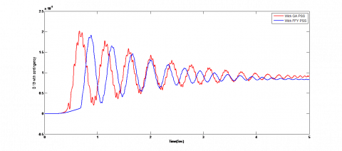
Figure 11. Response of ω 12 with contingency and with GA, FFY PSS
Figure 12. Response of ω 23 with contingency and with GA, FFY PSS
Figure 13. Response of ω13 with contingency and with GA, FFY PSS
Figure 14. Response of δ 12 with contingency and with GA, FFY PSS
Figure 15. Response of δ 23 with contingency and with GA, FFY PSS
Figure 16. Response of δ 13 with contingency and with GA, FFY PSS
From the responses shown above, it essential to compute the settling time for the various cases for comparison the effectiveness of the proposed method with the existing approach.
Figure 17. Settling times of ω12, ω23, ω13 with GAPSS and FFY PSS under contingency
It is clear that by from the observation of the settling time of the angular velocities and the load angles of the system under contingency condition, the oscillations are more in the responses and the settling time is more for stabilizing the values of the differences in the angular velocity and the load angles of the multi machine system.
The dominant states of the hydro thermal inter connected multi machine system with the problem of contingency are observed from the above mentioned step responses from the Fig 11 to Fig.16. By applying the contingency problem the line with maximum loading parameter is removed from the system and analyzed by designing the power system stabilizer with genetic algorithm and the firefly algorithms.
After careful observation of the Eigen values, the pseudo spectrum analysis, the proposed PSS is giving more stable Eigen values. The deviations of the inter machine parameters like speed variations and the rotor angle variations between machine 1-2; 2-3; 3-1 must settle at faster rate. The responses of speed deviations between the inter machines mentioned are settling to result the stable Eigen values. From the above discussion and observations, in addition to get the stable Eigen values the need of the settlement of the responses of the inter machines at zero position is the essential condition.
A contingency problem is solved in this article in the aspects of stability. After observation of the Eigen values without power system stabilizer, the system is said to be unstable system since the real part of the Eigen values are obtained as positive values. The power flow is also gets affected by the creation of the contingency problem in the interconnected system. The essential need of the stabilizer is evident from the Eigen spectrum analysis. The power system stabilizer is designed by using the proposed method and the results are compared with the genetic algorithm based power system stabilizer. The difference between the angular velocities of the machines 1-2, 2-3 and 3-1 are done by using the Matlab simulation.
By the observation of the step responses of the interconnected machines angular velocity and the load angles with the power system stabilizer, it is concluding that the proposed stabilizer is able to shift the unstable Eigen values to the stable side of the complex plane effectively.
|
System matrices notations |
|
|
Am |
System Matrices without controller |
|
Ac |
System matrix without controller under contingency |
|
B |
Control matrix |
|
x |
State Vector without controller |
|
u |
Control Vector |
|
Ksi |
Stabilizer gain for each machine for i=1, 2, 3. |
|
T1i, T2i |
Phase lead compensator time constants for each machine for i=1,2,3 |
|
System Parameters |
|
|
KA |
Voltage regulator gain |
|
TA |
Time constant of the voltage regulator |
|
K1i to K6i |
K Constants of the synchronous machine modeling |
|
T’d0 |
Direct axis transient open circuit time constant |
|
M |
Inertia coefficient |
|
D |
Coefficient of damping |
|
State Variables |
|
|
wi |
Angular velocity of i number of machines=1, 2, 3. |
|
di |
Torque angle of i number of machines=1, 2, 3. |
|
e’qi |
q-axis component of voltage behind transient reactance of i number of machines=1, 2, 3. |
|
eFDi |
Equivalent excitation voltage of i number of machines=1, 2, 3. |
|
VSi |
Stabilizer output for three machines for i=1, 2, 3. |
Adbennonr A. B., Lee K. Y. (1996). A decentralized controller design for a power plant using robust local controllers and functional mapping. FEET-Energy Conversion, Vol. 11, No. 2, pp. 394-400. https://doi.org/10.1109/60.507651
Anderson J. H. (1971). The control of a synchronous machine using optimal control theory. Proc. EEE, Vol. 59, pp. 25-35. https://doi.org/10.1109/PROC.1971.8086
Andreoiu A., Bhattacharya K. (2002). Lyapunov's method based genetic algorithm for multi-machine PSS tuning. IEEE Power Engineering Society Winter Meeting, pp. 1495-1500. https://doi.org/10.1109/PESW.2002.985273
Asija D., Choudekar P., Soni K. M., Sinha S. K. (2015). Power flow study and contingency status of WSCC 9 bus test system using MATLAB. 2015 International Conference on Recent Developments in Control, Automation and Power Engineering (RDCAPE). https://doi.org/10.1109/RDCAPE.2015.7281420
Babaei E., Galvani S., Ahmadi J. M. (2009). Design of robust power system stabilizer based on PSO. Industrial Electronics & Applications, ISIEA 2009. IEEE conference, Vol. 1, pp. 325-330. https://doi.org/10.1109/ISIEA.2009.5356455
Dill G. K., Silva A. S. E. (2011), Power system stabilizer design using optimization and pseudo spectra. Paper accepted for presentation at the IEEE Trondheim Power Tech. https://doi.org/10.1109/PTC.2011.6019377
Fleming R. J., Mohan M. A., Parvatisam K. (1981). Selection of parameters of stabilizers in multi machine power systems. IEEE Transactions on Power Apparatus and Systems, Vol. PAS-100, pp. 2329-2333. https://doi.org/10.1109/TPAS.1981.316752
Goldberg D. E. (1989). Genetic algorithm in search, optimization and machine learning. Addison-Wesely, Reading MA. https://doi.org/10.1111/j.1365-2486.2009.02080.x
Gurrala G., Sen I. (2010). Power system stabilizers design for interconnected power systems. IEEE transactions on power systems, Vol. 25, No. 2, pp. 1042-1051. https://doi.org/10.1109/TPWRS.2009.2036778
Hassan M. A. M., Malik O. P., Hope G. S. (1991). A fuzzy logic based stabilizer for a synchronous machine. IEEE Trans. EC, Vol. 6, No. 3, pp. 407-413. https://doi.org/10.1109/60.84314
Humpage W. D., Smith J. R., Rogers G. J. (1973). Application of dynamic optimization to synchronous generator excitation controllers. Proc IEE, Vol. 120, pp. 87-93. https://doi.org/10.1049/piee.1973.0017
Mahabuba A., Khan M. A. (2013). Small signal stability enhancement of a multi‐machine power system using robust and adaptive fuzzy neural network‐based power system stabilizer. European Transactions on Electrical Power, Vol. 19, No. 7, pp. 978-1001. https://doi.org/10.1002/etep.276
Moussa H. M., Yu Y. N. (1972). Optimal power system stabilization through excitation and/or governor control. IEEE Transactions on Power Apparatus and Systems, Vol. PAS-91, pp. 1166-1174. https://doi.org/10.1109/TPAS.1972.293473
Moussa H. M., Yu Y. N. (1974). Dynamic interaction of multi-machine power system and excitation control. IEEE Transactions on Power Apparatus and Systems, Vol. PAS-93, pp. 1150-1158. https://doi.org/10.1109/TPAS.1974.294061
Pandeno P. L., Karas A. N., Clymontand K. R. Watson W. (1968). Effect of high-speed rectifier excitation systems on generator stability limits. IEEE Transactions on Power Apparatus and Systems, Vol. PAS-87, pp. 190-201. https://doi.org/10.1109/TPAS.1968.292271
Rashidi M., Rashidi F., Moaavar H. (2003). Tuning of power system stabilizers via genetic algorithm for stabilization of power systems. IEEE Transactions, Vol. 5, pp. 4649-4654. https://doi.org/10.1109/ICSMC.2003.1245717 ·
Schleif F. R., Hunkins H. D., Hattan E. E., Gish W. B. (1969), Control of rotating exciters for power system damping: Pilot applications and experience. IEEE Transactions on Power Apparatus and Systems, Vol. PAS-88, pp. 1259-1266. https://doi.org/10.1109/tpas.1969.292475
Yu Y. N., Moussa H. A. M. (1972). Optimal stabilization of a multi machine system. IEEE Transactions on Power Apparatus and Systems, Vol. PAS-91, pp. 1174-1182. https://doi.org/10.1109/tpas.1972.293474
Yu Y. N., Siggers C. (1971). Stabilization and optimal control signals for a power system. IEEE Transactions on Power Apparatus and Systems, Vol. PAS-90, pp. 1469-1481. https://doi.org/10.1109/tpas.1971.293131
Yu Y. N., Vongsuriya K., Wedman L. N. (1970). Application of an optimal control theory to a power system. IEEE Transactions on Power Apparatus and Systems, Vol. PAS-89, pp. 55-62. https://doi.org/10.1109/tpas.1970.292668