Chaouki Melkia* | Sihem Ghoudelbourk | Youcef Soufi | Mahmoud Maamri | Mebarka Bayoud
© 2022 IIETA. This article is published by IIETA and is licensed under the CC BY 4.0 license (http://creativecommons.org/licenses/by/4.0/).
OPEN ACCESS
In this paper, we proposed, modelled, and then simulated a standalone photovoltaic system with storage composed of conventional batteries and a Supercapacitor was added to the storage unit in order to create hybrid storage sources (batteries and Supercapacitor), and to better relieve the batteries during peak power. And reduce stress on the batteries by avoiding deep discharges. This study includes, on the one hand, a MPPT (Maximum Power Point Tracking) algorithm integrated to the control of this converter allowing the photovoltaic panels to operate according to their optimal nominal voltage, thus providing the maximum power. On the other hand, efficient global management allows the system to offer optimal performance.
energy management, hybrid storage, photovoltaic panels, MPPT, batteries, Supercapacitor
In the context of ecological crisis, global warming, scarcity of fossil resources, and continuous growth in energy demand, governments around the world are gradually abandoning fossil fuels and turning to renewable energies.
Renewable energies appear as one of the ideal solutions to produce green energy [1]. The among of these, photovoltaics is the most exploited technology in the world, it occupies a special place for several reasons: the energy of the sun is inexhaustible, available everywhere, free, and the production of energy does not emit greenhouse gases [2].
Due to the nonlinear nature of the photovoltaic panels 'characteristics, their voltage is highly dependent on the connected load. To correct this problem, MPPT (Maximum Power Point Tracking) devices allow the panels to operate under optimal conditions and thus extract the maximum power. And one of the solutions to the intermittency problems is to perfect a storage system by adding batteries with super capacities. The use of batteries is widespread in the field and allows for reaching a rather attractive performance/cost ratio. However, their performance degrades rapidly when they are subjected to extreme conditions of use [3].
In this contexte Numerous studies examining the benefits of energy saving and storage for generation, transmission and distribution applications, including what is in the theoretical framework of planning and control to maximize the gain of battery energy storage systems for basic frequency control where the maximum potential revenue of power modulation and frequency regulation is investigated; some studies also touched upon an optimal real-time transfer algorithm for energy storage. The optimum operation of battery energy storage has been studied to mitigate photovoltaic (PV) fluctuations and reduce transformer losses. There has been a great deal of work on battery management systems (BMSs). [4, 5]
This research paper addresses the following issue: in order to design and optimize an energetically autonomous photovoltaic system, and to reach this objective, it will be necessary to overcome the two main problems related to the production of photovoltaic energy in isolated sites, which are the difficulty of operating according to an optimal point and efficient storage of the energy produced.
Thus, the addition of a Supercapacitor provides a better response to sudden changes in climatic conditions (solar radiation) but also to sudden changes in demand [3]. And to optimally manage the power flow of the Hybrid Energy Storage system (HESS) and regulate the Direct Current (DC) bus voltage during source and load variations. The Power Management Strategy (PMS) is implemented in the control block [6] to control the energy exchange between the different system components on the one hand and to regulate the charge/discharge storage process on the other hand [2].
This paper is organized as follows: the second section is dedicated to the description and modeling of the PV power system. In The third section a PMS is implemented in the control block to manage the power flow between the different components of the HESS (Hybrid Energy Storage System) to achieve different objectives: In the fourth sections, the simulation results are given, followed by a conclusion at the end of this paper.
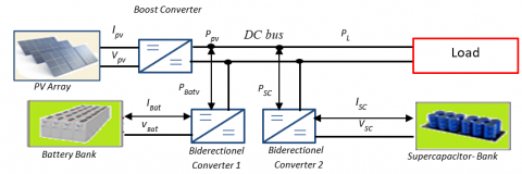
The proposed stand-alone photovoltaic system with hybrid storage consists of a PV generator connected to a DC bus via a DC-DC boost converter, and a group of lithium-ion batteries as a long-term storage system used in case of over-consumption or under-supply, based on the characteristics of fast charging at different temperatures, and The extended life cycle of this type of rechargeable battery according to the proposed model represents a more suitable option, compared to the lead-acid battery [3, 7].and a set of supercapacitors to cope with rapid transitions in power demand, each ESS (Electrical Energy Storage) is connected to the DC bus via a DC-DC buck-boost converter, loads, a three-phase inverter connected to the DC bus is used to power the load and control systems. As shown in Figure 1.
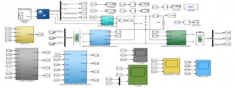
The PV system is affected by different weather conditions such as irradiation. Therefore, MPPT control is used to extract the maximum power from the PV via DC/DC amplification for proper operation of the PV system which is achieved using the Perturbation and Observation (P&O) method, and Power transfer is produced between these components via conventional energy. Management system. The proposed model is developed and simulated using MATLAB/Simulink software based on mathematical analysis and the average modelling is shown in Figure 2.
Figure 1. Block diagram of PV systems with energy storage
Figure 2. Diagram of the simulation of the PV system with hybrid storage in MATLAB-Simulink
2.1 GPV modelling
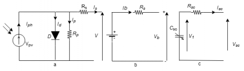
Figure 4(a) represents the electrical model of a PV cell consisting of a photocurrent and a diode describing the properties of the semiconductor [8]. A series resistances $\mathrm{R}_s$ represents an internal resistance, and a parallel resistance $\mathrm{R}_p$ showing a leakage current [6].
The mathematical equation expressing the charging current can be given as [9]:
$\mathrm{I}=\mathrm{I}_{\mathrm{ph}}-\mathrm{I}_{\mathrm{s}}\left[\mathrm{e}^{\left(\frac{\mathrm{qv}+\mathrm{IR}_{\mathrm{s\quad}}}{\mathrm{kT}_{\mathrm{c}} \mathrm{A}}\right)}-1\right]-\left(\frac{\mathrm{v}+\mathrm{IR}_{\mathrm{s}}}{\mathrm{R}_{\mathrm{p}}}\right)$ (1)
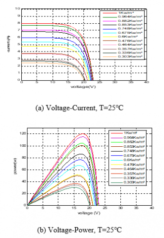
Based on Eq. (1) we see that the physical behavior of the PV cell is also related to temperature and solar radiation [6], so for a given temperature of 25℃, and variable radiation. The I-V and P-V curves are generated as shown in Figure 3.
Figure 3. Characteristics of the PV system with variable solar radiation
2.2 Battery modelling
The model is shown in Figure 4(b), it consists of a voltage source corresponding to the open circuit voltage source $\mathrm{E}_0$ in series with an equivalent internal resistance $\mathrm{R}_S$ [10].
The terminal voltage of the battery is given by the Eq. (2) [11].
$\mathrm{V}_{\mathrm{b}}=\mathrm{E}_0-\mathrm{I}_{\mathrm{b}} \cdot \mathrm{R}_{\mathrm{s}}$ (2)
The state of charge (SOC) of the battery is also defined by:
SOC $=1-\frac{Q_d}{C_b}$ (3)
where $C_b$ is the nominal capacity (Ah) of the battery, and $\mathrm{Q}_{\mathrm{d}}$ is the amount of charge missing from $C_b$ [2].
2.3 Supercapacitor modelling
This is a simple electrical circuit model consisting of a resistor $\mathrm{R}_{\mathrm{sc}}$ and a capacitor $\mathrm{C}_{\mathrm{sc}}$ in series (Figure 4(c)). This model is commonly used for the study of energy systems.
The expression for the SC voltage $\mathrm{V}_{\mathrm{SC}}$ is given by Eq. (4) [11].
$\mathrm{V}_{\mathrm{sc}}=\mathrm{V}_1-\mathrm{R}_{\mathrm{sc}} \cdot \mathrm{I}_{\mathrm{sc}}=\frac{\mathrm{Q}_{\mathrm{sc}}}{\mathrm{C}_{\mathrm{sc}}}-\mathrm{R}_{\mathrm{sc}} \cdot \mathrm{I}_{\mathrm{sc}}$ (4)
Figure 4. Electrical model of a) PV cell, b) Battery, c) Supercapacitor
2.4 DC/DC converter modeling
Choppers are static DC-DC converters whose function is to provide a variable DC voltage from a fixed DC voltage. This energy conversion is carried out thanks to a high-frequency “chopping” characterized by high efficiency.
Figure 5. DC/DC converter diagram
If the output voltage is lower than the input voltage, the chopper is called a buck (BUCK). Otherwise, it is said to be a booster (BOOST). The study of the simplest static DC-DC converters is divided into three families of converters:
-Boost converter,
-Buck converter,
-Buck-Boost converter,
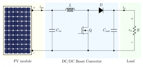
Figure 5 illustrates a photovoltaic system adapted by a Boost-type converter feeding a resistive load R.
The capacitor is charged by the current coming from the generator and stored in the inductor during the first phase of operation. It is used to smooth the output voltage.
$V_{C h}=E\left(\frac{1}{1-\alpha}\right)$ (5)
$I_{C h}=(1-\alpha) I$ (6)
Figure 6. Electric circuit of the Boost converter
Figure 7. DC/DC Buck converter
In this type, the average output voltage is higher than the input voltage. It is also called a parallel converter. This structure requires a controlled switch and is in parallel with the source (Figure 6). The duty cycle, chopping period (T), has two states.
A state of energy accumulation: when the switch k is closed (on the state), this leads to an increase in the current in the inductance and therefore the storage of a quantity of energy in the form of magnetic energy. The diode is then blocked and the load is disconnected from the power supply. This phase lasts from (0) to ($\alpha \mathrm{T}$);
When the switch k is open, the inductance is then in series with the Generator and its e.m.f is added to that of the generator (booster effect). The current flowing through the inductor then crosses the diode, the capacitor and the load. This results in a transfer of the energy accumulated in the inductor to the capacitor. This phase lasts from ($\alpha \mathrm{T}$) to (T). The equations for voltage and current in the load are:
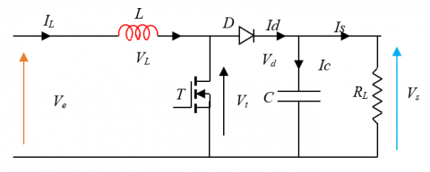
This type of converter is used to produce a higher voltage than that supplied by the photovoltaic generator (Figure 7).
The proposed system (Figure 1) contains two transistor switches, the method of controlling which determines the mode of bidirectional converter operation (buck or boost):
A. Discharge mode:
For the first phase T: closed, D: open
$\left\{\begin{array}{l}\frac{d I_L}{d t}=\frac{1}{L}\left(V_e-V_s\right) \quad(0<t<\alpha T s) \\ \frac{d V e}{d t}=\frac{1}{C}\left(I_L\right)-\frac{V s}{R C}\end{array}\right.$ (7)
For the second phase T: open, D: closed
$\left\{\begin{array}{l}\frac{d I_L}{d t}=-\frac{1}{L}(V s) \\ \frac{d V e}{d t}=\frac{1}{C}\left(I_L\right)-\frac{V s}{R C}\end{array} \quad(\alpha T s<t<T s)\right.$ (8)
So, the output voltage is
$V_s=\alpha \ V e$ (9)
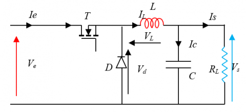
B. Charge mode:
For the first phase T: closed, D: open
$\left\{\begin{array}{l}\frac{d I_L}{d t}=\frac{1}{L}\left(V_e\right) \\ \frac{d V e}{d t}=-\frac{V s}{R C}\end{array}\left(0<t<\alpha T_s\right)\right.$ (10)
For the second phase T: open, D: closed
$\left\{\begin{array}{l}\frac{d I_L}{d t}=\frac{1}{L}\left(V_e\right)+\frac{1}{L}\left(V_s\right)(\alpha T s<t<T s) \\ \frac{d V e}{d t}=\frac{1}{C}\left(I_L\right)-\frac{V e}{R C}\end{array}\right.$ (11)
Output voltage is:
$V s=V e \cdot \frac{1}{1-\alpha}$ (12)
2.5. MPPT for GPV
Since the considered DC microgrid is a PV-based system, it is essential to operate the PV source at its maximum power point [12].
(a)
(b)
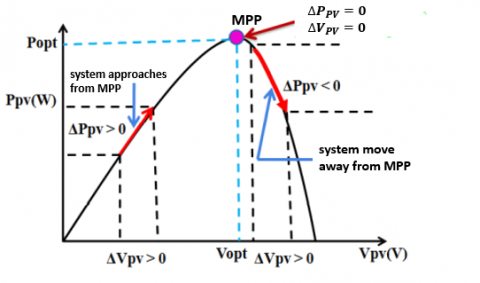
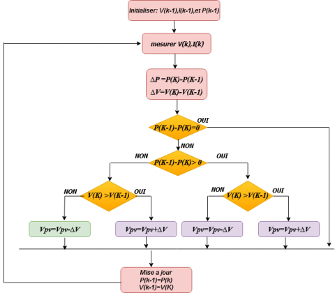
Figure 8. (a) Principle of the P&O method algorithm, (b) P&O Algorithm
By adjusting the duty cycle of the DC/DC converter [13]. The Perturber & Observer method is based on perturbation by increasing or decreasing the module's operating voltage $\mathrm{V}_{\mathrm{PV}}$ of a small amplitude around its initial value and analyzing the behavior of the resulting power variation $\mathrm{P}_{\mathrm{PV}}$ [14]. If ΔP is positive, it means that the operating point is to the left of the MPP. If, on the contrary, the power decreases, it implies that the system has already exceeded the MPP (Figure 8-a) [2]. The parameter used in this method is the PV generator voltage ($\mathrm{V}_{\mathrm{K}}$) which must be calculated at time k and the current of the PV generator ( $\mathrm{I}_{\mathrm{K}}$ ) and then we have the $\mathrm{P}_{\mathrm{K}}$ which is compared to the previous disturbance time cycles ( $\mathrm{P}_{\mathrm{K-1}}$ ). If the comparison value shows zero, the maximum power point has been reached (Figure 8-b). As soon as the MPP is reached, V oscillates around the ideal operating voltage [15-17].
A PMS is implemented in the control block to manage the power flow between the different components of the HESS (Hybrid Electric Energy Storage) system to achieve different objectives: reduce the dynamic stress level of the battery [15], regulate the DC bus voltage during source and load variations [6], prevent the deep discharge of the battery and improve overall system efficiency [15].
The supervision algorithm is based on two different modes; the Excess Power mode (EPM) represents the period when generated PV power is higher than the required load power. And Deficit Power Mode (DPM) is the period when the generated PV power is less than the required load power. As we can see two scenarios in this mode: powering the load by PV panels and storage if insufficient solar energy, or powering the load only by storage if solar energy is absent [2].
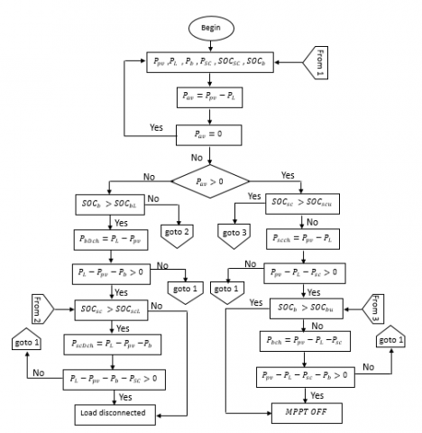
3.1 The Algorithm
1. All parameters are observed, $\mathrm{P}_{\mathrm{pv}}, \mathrm{P}_{\mathrm{L}}, \mathrm{P}_{\mathrm{b}}, \mathrm{P}_{\mathrm{Sc}}, \mathrm{SOC}_{\mathrm{Sc}}$ and, $\mathrm{SOC}_{B a t}$ (show Figure 9).
2. Calculate $\mathrm{P}_{\mathrm{av}}=\mathrm{P}_{\mathrm{pv}}-\mathrm{P}_{\mathrm{L}}$ ;
3. Check the condition $\mathrm{P}_{\mathrm{av}}=0$, if true go to 1, otherwise go to the next step;
4. Check the condition $\mathrm{P}_{\mathrm{av}}>0$, if it is false, go to the next step else go to step 9;
5. Check $\mathrm{SOC}_{\mathrm{b}}>\mathrm{SOC}_{\mathrm{bL}}=$, if it is true, discharge the battery and go to the next step if not go to 7;
6. Check the condition $\mathrm{P}_{\mathrm{L}}-\mathrm{P}_{\mathrm{pv}}-\mathrm{P}_{\mathrm{b}}>0$, if true then go to the next step, otherwise go to 1;
7. Check $\mathrm{SOC}_{\mathrm{sc}}>\mathrm{SOC}_{\mathrm{scL}}$, if true then unload the SC and go to the next step otherwise disconnect the load;
8. Check the condition $P_L-P_{p v}-P_b-P_{S c}>0$, if true then disconnect the load, else go to 1;
9. Check $\mathrm{SOC}_{\mathrm{sc}}>\mathrm{SOC}_{s c u}$, if false, load SC and go to the next step else go to 11;
10. Check the condition $P_{p v}-P_L-P_b>0$, if true, go to the next step, otherwise, go to 1;
11. check, $\mathrm{SOC}_{\mathrm{b}}>\mathrm{SOC}_{\mathrm{bu}}$ if false, charge the battery and go to the next step otherwise MPPT is disabled;
12. Check the condition $P_{p v}-P_L-P_b-P_{S C}>0$, if true then MPPT off else go to 1 [2, 3, 15].
Figure 9. Power management strategy
where, Ppv, PL, represent photovoltaique power and Load power, VBat, PBat, IBat, SOCBat represent respectively Voltage, Power, Current and State of charge of Battery and VSC, PSC. ISC, SOCSC represent respectively Voltage, Power, Current and State of charge of Supercapacitor.
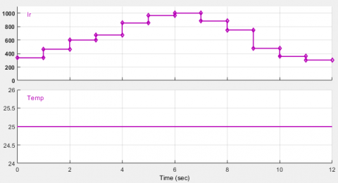
In this scenario, variable solar irradiation is used, as shown in Figure 10, and the load is assumed to be constant throughout the experiment and equal to 500 watts. Figure 11 shows the performance of the proposed PMS under variable solar irradiation such that when the panels produce enough energy to meet the load requirements; the surplus is used to recharge the supercapacitor and batteries.
The Parameters of PV generator, Supercapacitor, and battery are shown in Tables 1, 2, and 3 respectively.
Table 1. PV generator properties
|
Module |
Ware energies wu-120 |
|
Parallel strings |
4 |
|
Series-connected modules per string |
2 |
|
Cells per module |
72 |
|
Maximum power (W) |
120.7 |
|
Open circuit voltage (V) |
21 |
|
The voltage at maximum power point (V) |
17 |
|
Current at maximum power point (A) |
7.1 |
|
Short-circuit current (A) |
8 |
|
Light-generated current (A) |
8.0496 |
|
Diode saturation current (A) |
2.4168e-10 |
|
Shunt resistance (Ohms) |
31.6334 |
|
Series resistance (Ohms) |
0.196 |
Table 2. Supercapacitor properties
|
Rated capacitance (F) |
29 |
|
Equivalent DC series resistance (Ohms) |
0.003 |
|
Rated voltage (V) |
32 |
|
Initial voltage (V) |
32 |
|
Operating temperature (C) |
25 |
Table 3. Battery properties
|
Nominal voltage (V) |
24 |
|
Cut-off Voltage (V) |
18 |
|
Fully charged voltage (V) |
27.9357 |
|
Nominal discharge current (A) |
6.087 |
|
Maximum capacity (Ah) |
14 |
|
Rated capacity (Ah) |
14 |
|
Capacity at a nominal voltage (Ah) |
12.6609 |
|
Internal resistance (Ohms) |
0.017143 |
|
Initial state-of-charge (%) |
50 |
|
Battery response time (s) |
0.1 |
Figure 10. Solar radiation and temperature
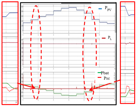
Figure 11. Responses of $P_{p V}, P_L, P_{b a t}$ and $\mathrm{P}_{\mathrm{SC}}$ with variable solar radiation
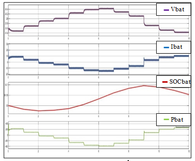
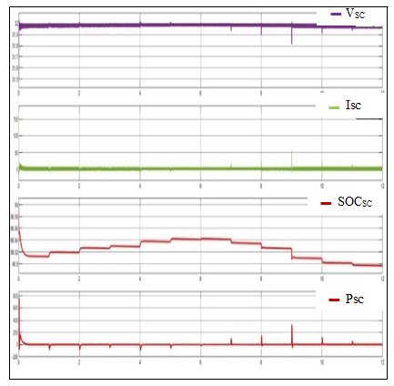
Figure 12 and Figure 13 show the responses of and with varying solar irradiance. These results illustrate the efficiency of the supercapacitor when storing or releasing energy to reduce stress on the battery. As early t=2s, the power delivered by the panels increases from 400 to 600 watts and thus becomes higher than the consumption. During this short period, the power delivered by the battery tends towards a negative value (Figure 12) which is logical since the demand is met by the energy from the panels. And the battery switches from discharge to charge mode.
There is an excess of power during this period which is stored in the SC. The power of the panels continues to increase as the irradiation increases in steps and it is observed that at each sudden change in power, the Supercapacitor reacts to the change in a very short time.
In this time interval from 0 to 2s and from 9 to 12s, the power of the panels is lower than the power demanded by the load. The battery supplies the power deficit to the load (positive current and battery power respectively in Figure 13. At t=9s. There is a sharp drop in panel power from 700 to 470 watts in a very short time. On this same delay, the battery switches from charge to discharge mode with respect SOC (state of charge), and the Supercapacitor reacts to the deficit first and feeds the load and the battery afterwards, and at t = 2s we see that the surplus is used to recharge the supercapacitor first, then the batteries. With each sudden decrease or increase in the panel power, the supercapacitor continues to respond by supplying or absorbing power in a short period of time.
Figure 12. Vbat, Ibat, SOCbat, and PBatr
Figure13. Vsc, Isc, SOCsc, and $P_{s c}$
In this research paper, we have realized and optimized an autonomous photovoltaic energy system with hybrid storage ensuring continuous energy availability. This system operates at its optimal power by using a DC/DC converter through the optimization of the MPPT algorithm, and it ensures continuity of service through the energy management algorithm. A simulation with the interpretation of the results of the overall system storage management was proposed for different operating conditions, to show the different operating modes of the management algorithm for the whole system. And the results also show that the Supercapacitor contributes to the optimal operation of the batteries and supports current peaks and thus relieving the batteries and increasing their lifetime.
[1] Cabrane, Z., Kim, J., Yoo, K., Ouassaid, M. (2021). HESS-based photovoltaic/batteries /supercapacitors: Energy management strategy and DC bus voltage stabilization. Sol. Energy, 216: 551-563. http://doi.org/10.1016/j.solener.2021.01.048
[2] Singo, A.T. (2010). Système d'alimentation photovoltaïque avec stockage hybride pour l'habitat énergétiquement autonome (Doctoral dissertation, Université Henri Poincaré-Nancy 1). https://hal.univ-lorraine.fr/tel-01748214, accessed on Sept. 27, 2022.
[3] Hassan, S.Z., Li, H., Kamal, T., Mumtaz, S., Khan, L., Ullah, I. (2016). Control and energy management scheme for a PV/SC/battery hybrid renewable power system. Sci. Int., 28(2): 955-964.
[4] Jing, W., Hung Lai, C., Wong, S.H.W., Wong, M.L.D. (2017). Battery‐supercapacitor hybrid energy storage system in standalone DC microgrids: A review. IET Renewable Power Generation, 11(4): 461-469. http://dx.doi.org/10.1049/iet-rpg.2016.0500
[5] Chotia, I., Chowdhury, S. (2015). Battery storage and hybrid battery supercapacitor storage systems: A comparative critical review. IEEE Innovative Smart Grid Technologies-Asia (ISGT ASIA) (2015): 1-6. https://doi.org/10.1109/ISGT-Asia.2015.7387080
[6] Singh, P., Lather, J.S. (2020). Power management and control of a grid-independent DC microgrid with hybrid energy storage system. Sustain. Energy Technol. Assessments, 43: 100924. http://doi.org/10.1016/j.seta.2020.100924
[7] Ali, N.B.S., Ghoudelbourk, S., Zerzouri, N. (2022). Battery-supercapacitor hybrid energy storage systems for stand-alone photovoltaic. European Journal of Electrical Engineering, 24(4): 161-169. https://doi.org/10.18280/ejee.240404
[8] Zouli, M., Ghoudelbourk, S., Ouari, A., Dib, D. (2017). Influence of the external and internal parameters on the characteristics of generator PV. AIP Conference Proceedings, 1814. http://doi.org/10.1063/1.4976226
[9] Ghoudelbourk, S., Dib, D., Meghni, B., Zouli, M. (2017). Selective harmonic elimination strategy in eleven-level inverter for PV system with unbalanced DC sources. AIP Conference Proceedings, 1814. http://doi.org:/10.1063/1.4976227
[10] Bhavani, C.S.G., Kishore, D.R. (2020). Battery protection scheme integrated with demand side management in stand-alone hybrid microgrid. Sustainable Energy, Signal Processing and Cyber Security (iSSSC). http://doi.org/ 10.1109/iSSSC50941.2020.9358847
[11] Kadri, A., Marzougui, H., Aouiti, A., Bacha, F. (2016). Energy management and control strategy for a DFIG wind turbine/fuel cell hybrid system with supercapacitor storage system. Energy, 192: 116518. http://doi.org/10.1016/j.energy.2019.116518
[12] Ravada, B.R., Tummuru, N.R. (2020). Control of a Supercapacitor-Battery-PV based stand-alone DC-Microgrid. IEEE Trans. Energy Convers, 35(3): 1268-1277. http://doi.org/ 10.1109/TEC.2020.2982425
[13] Felten, J. (2021). Architecture et étude d’un système électrique hybride destine a l’autonomie d’une zone rurale. Free Radic. Biol. Med. 52: 1075-1085. https://hal.univ-lorraine.fr/tel-03132500, accessed on Sept. 17, 2022.
[14] Priyono, W., Wijayan, D.F., Firmansyah, E. (2018). Study and simulation of a hybrid stand-alone PV system for a rural telecommunications system. Proc. - 3rd Int. Conf. Inf. Technol. Inf. Syst. Electr. Eng. ICITISEE 2018: 418-422, http://doi.org/10.1109/ICITISEE.2018.8721000
[15] Ghoudelbourk, S., Azar, A.T.; Dib, Djalel, Omeiri, A. (2020). Selectivee harmonic elimination strategy in the multilevel inverters for grid connected photovoltaic system. Int. J. Advanced Intelligence Paradigms, 15(3): 317-339. https://doi.org/10.1504/IJAIP.2020.105826
[16] Guentri, H., Allaoui, T., Mekki, M., Denaim, M. (2021). Power management and control of a photovoltaic system with hybrid battery-supercapacitor energy storage based on heuristics methods. J. Energy Storage, 39. http://doi.org/ 10.1016/j.est.2021.102578
[17] Rechach, A., Ghoudelbourk, S., Larbi, M.M. (2022). Impact of choice of neutral point clamped and h-bridge multilevel inverters for PV systems. European Journal of Electrical Engineering, 24(4): 213-219. https://doi.org/10.18280/ejee.240406