Helima Slimani* | Abdelhakim Zeghoudi | Abdelber Bendaoud | Abdeldjalil Reguig | Baghdadi Benazza | Nassireddine Benhadda
© 2021 IIETA. This article is published by IIETA and is licensed under the CC BY 4.0 license (http://creativecommons.org/licenses/by/4.0/).
OPEN ACCESS
The commutation of semiconductors and their interactions with parasitic elements linked to the environment is known to be the main source of interferences conducted in power electronic converters. Thus, identifying these sources of interferences in commutation cells and determining the level of these conducted emissions generated in energy conversion systems presents a major challenge for designers. In this work, a study of the electromagnetic interferences (EMI) generated by the association of serial rectifier-chopper connected to a Line Impedance Stabilization Network (LISN) is proposed, in which a determination of these interferences is presented in both common and differential modes. All simulations are carried out using the LT-spice software and the results obtained are validated by experimental measurements realized at APELEC laboratory (University of Sidi Bel-Abbes, Algeria).
EMI, static converter, LISN, common mode, differential mode, simulation, measurement
The number of devices used in power electronics has been significantly increased in the recent years. Based on semiconductor commutations operation, these devices are used nowadays in several domains such as land and air transport, domestic applications destined to the general public consumers as well as in renewable energies [1, 2].
The operation of the static converter is polluting the environment due to its commutation times that are very short at very high amplitudes. These fast commutations operations reduce losses during commutations as consequence of the presence of the voltage and current simultaneously within the interrupters. The orders of magnitude of the commutation gradients can vary between 100 to 1000 A/μs for the dI/dt and from 5 to 50 kV/μs for the dV/dt. Moreover, very high commutation frequency is another factor that increases the electromagnetic pollution, as it can vary from 100 Hz to 1 MHz. This condition presents a serious problem in regards to the Electromagnetic Compatibility (EMC), in which we face:
- Conducted interferences (Common Mode),
- Radiated interferences.
In power electronics, a conversion chain generally involves several conversion stages as highlighted in Figure 1. These stages often consist of: a rectifier followed by a commutation stage such as speed variators, a switching power supply, and an inverter for induction heating systems, etc. The study of the electromagnetic compatibility can be performed at several levels like the power lines, rectifier, converter and its control, filtering, the load, etc. [3-6]. In the present work, we investigated the conducted interferences.
Figure 1. Example of a power electronics conversion chain [4, 6]
The first step of evaluating the conducted emission interferences consist of determining the sources of theses interferences. In an electromechanical chain, the identification of these sources is immediate and intuitive. The main conducted EMC interferences are generated by the commutation of the power switches of static converters. These state changes generate strong variations in voltage (dV/ dt) as well as in current (dI/dt).
The brutal variations of the voltage associated with parasitic elements between the system and the ground plane induce disturbing currents in the ground circuits. Therefore, active elements in the converter such as power semiconductors are the main interference sources of voltages and currents [7-9].
The conducted type of electromagnetic interferences manifest at highly variable frequencies and origins.
As shown in Figure 2, the origins of interferences could be identified according to their frequency ranges.
At low frequencies, from 10 Hz to 10 kHz, interferences are due to the harmonics related to the rotation frequency of the electrical machine. Then, the harmonics associated with the switching of the interrupters of the energy converter occur in the frequency range of 10 kHz to 1 MHz. At high frequency domain, there is first, a range of 500 kHz to 100 MHz, in which the harmonics depend on the commutation mechanisms, and the parasitic phenomena that appear during commutation. Finally, the last frequency band range is beyond 100 MHz in which the strikes linked to the control of the switches appear, such as driver, grid control, etc. [9, 10].
Figure 2. Frequency range of the conducted electromagnetic interferences [6]
Conducted electromagnetic interferences fall into two categories, differential mode (DM) on one hand and common mode (CM) interferences on the other. The differential mode current flow forms the link between the devices, as highlighted in Figure 3(a).
(a) differential mode (b) common mode
Figure 3. Conducted disturbances
In this example, the current IDM in the first "In" conductor is equal to the current in the second "Out" conductor. The circulation of the common mode current ICM forms a connection between the devices and the equipotential reference as well (Figure 3(b)). Thus, the common mode current is defined as the current flowing within the equipotential reference [11-16].
In the context of power electronics, the EMC aspects cover the following essential particularities:
The converters are, at the same time:
The external interferences from natural and industrial environments can also occur [17-20].
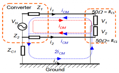
A simple case of conducted interferences emitted by a converter is presented in Figure 4. In this figure, VN represents the disruptive voltage of the converter. Z1 and Z2 represent the impedances of the noise propagation paths; ZC1 is the impedance between the device and the ground. Resistors RC1 and RC2 represent the load of the noise. These are normalized resistors (50 Ω) in which the parasitic voltages created in the victim are measured.
The differential mode current IDM flows in the loop between two power lines and the common mode current ICM flows in the overall loop, including the power lines and the ground [21, 22].
Figure 4. Pollutions in differential and common modes [21]
Thus, the real interference current in two power lines is:
$\mathrm{i}_{1}=-\mathrm{i}_{\mathrm{CM}}+\mathrm{i}_{\mathrm{DM}}$ (1)
$\mathrm{i}_{2}=-\mathrm{i}_{\mathrm{CM}}-\mathrm{i}_{\mathrm{DM}}$ (2)
$\mathrm{i}_{\mathrm{G}}=2 \mathrm{i}_{\mathrm{CM}}$ (3)
It is noted that the standards related to electromagnetic interferences indicate the noise voltage limits on a resistor of 50 Ω, thus, the following equations are established for the both voltages V1et V2, at the terminals of the resistors RC1 et RC2 respectively:
$\mathrm{V}_{1}=\mathrm{R}_{C}\left(-\mathrm{i}_{C M}+\mathrm{i}_{\mathrm{DM}}\right)$ (4)
$\mathrm{v}_{2}=\mathrm{R}_{\mathrm{C}}\left(-\mathrm{i}_{\mathrm{CM}}-\mathrm{i}_{\mathrm{DM}}\right)$ (5)
With, RC1 = RC2 = RC = 50 Ω.
The following mathematical expressions represent the voltage drops across the resistor RC due to current of differential mode (DM) and current of common mode (CM):
$\mathrm{v}_{\mathrm{MC}}=-50 \mathrm{i}_{\mathrm{MC}}=\frac{\mathrm{v}_{1}+\mathrm{v}_{2}}{2}$ (6)
$\mathrm{v}_{\mathrm{MD}}=-50 \mathrm{i}_{\mathrm{MD}}=\frac{\mathrm{v}_{1}-\mathrm{v}_{2}}{2}$ (7)
The voltages v1 and v2 could be calculated as follows:
$\mathrm{v}_{1}=\mathrm{V}_{\mathrm{MC}}+\mathrm{V}_{\mathrm{MD}}$ (8)
$\mathrm{V}_{2}=\mathrm{V}_{\mathrm{M} \mathrm{C}}-\mathrm{V}_{\mathrm{MD}}$ (9)
However, because of the distortion of the line current signal (useful signal) and the negative effects of electromagnetic interferences on the useful signals, and consequently on the quality of the delivered energy, this prompted standard-setters to set emission limits or emissivity of equipment and systems connected to the energy distribution network. These limits are reflected in standards imposing the maximum interferences limits produced by power electronic devices, as well as in the establishment of criteria preventing victim devices from being too sensitive to interferences (immunity limits) [22].
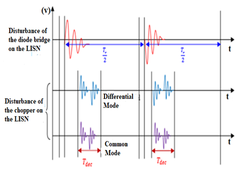
In this study, the impact of the spectrum of conducted interferences from the diode bridge on those of the chopper will be presented. The diode bridge is inserted between the LISN and the chopper. The interferences related to the rectifier manifest themselves directly in the LISN but those of the chopper see the measuring device through the rectifier only.
Three temporal functions Fbridge(t), FDM(t) and FCM(t) represent respectively: the interferences linked to the rectifier over a half-period of the network signal, in differential and in common modes of the converter over one chopping period.
The following form demonstrates the temporal function that represents all interferences over one period, at low frequency:
$F_{t o t}(t)=F_{\text {bridge }}(t)+F_{\text {chopp }}(t)$ (10)
The $F_{\text {bridge }}(t)$ function represents the interferences generated by the chopper over one period of the network signal in a clipping frequency assumed to be multiple of the network signal frequency. This function is itself defined by FDM et FCM.
$\mathrm{F}_{\text {chopp }}(\mathrm{t})=\mathrm{f}\left(\mathrm{F}_{\mathrm{DM}}(\mathrm{t}), \mathrm{F}_{\mathrm{CM}}(\mathrm{t})\right)$ (11)
Figure 5 highlights the temporal variations related to these three interferences signals.
Figure 5. Superimposition of the three interferences signals
5.1 Simulation of the Rectifier-Chopper Association
The simulation circuit is presented in Figure 6, where the inductive and capacitive parasitic elements are taken into consideration. The components used are: rectifier diodes of type 1N4007, a MOSFET of type IRF740 and another diode of type BYT12P1000. The MOSFET is controlled by a slot with a duty cycle of 40% and a commutation time of 670 µs. The assembly is connected to the LISN.
This circuit has the following data:
Vres = 20 V, f = 50 Hz, C = 940 μF, Rch = 82 Ω.
5.2 Experimental measurements
After realizing the two converters, the diode bridge single-phase rectifier and the serial chopper, an association has been made between them in order to measure the electromagnetic interferences.
Figure 6. Diagram of the Rectifier-Chopper association with the LISN built under Ltspice Software
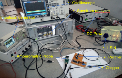
Figures 7 and 8 illustrate a descriptive diagram and a photograph of the experimental bench of the Rectifier-Chopper association in serial with the Line Impedance Stabilization Network (LISN), respectively.
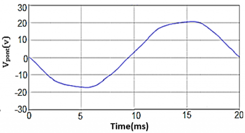
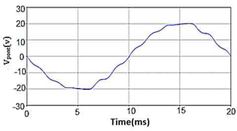
Figures 9(a) and 9(b) represent the temporal results of the voltage at the input of the rectifier obtained by simulation and by experiments respectively.
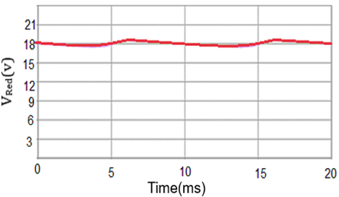
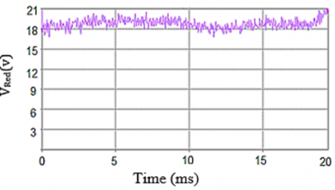
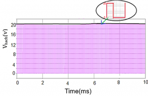
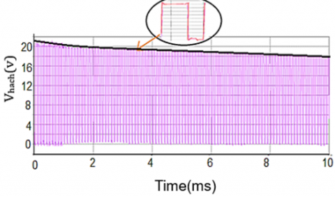
The rectified voltage and the voltage at the output of the chopper, obtained by simulation and by experiments, are shown in Figures 10 and 11 respectively.
Based on the different graphs, the voltage at the rectifier input has a waveform similar to that of the rectifier loaded by a simple resistor. However, in the rectified voltage waveforms, due to the commutations of the MOSFET and the diodes, a periodic oscillatory phenomenon is clearly visible when performing a zoom that corresponds to the commutation time interval. This phenomenon is similar to the studied one. It is due to the sudden commutation of switches and the effect of inductances of connection as well as the passive components of the converter.
Figure 7. Descriptive diagram of the experimental bench of a rectifier-chopper association
Figure 8. Photograph of the measurement bench of the electromagnetic interferences generated by the rectifier-chopper association
(a)
(b)
Figure 9. Temporal variation of the voltage at the input of the rectifier bridge: (a) Simulation results, (b) Experimental results
(a)
(b)
Figure 10. Temporal variation of the rectified voltage: (a) Simulation results, (b) Experimental results
(a)
(b)
Figure 11. Temporal variation of the Output voltage of the Rectifier-Chopper association: (a) Simulation results, (b) Experimental results
(a)
(b)
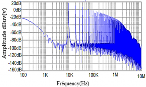
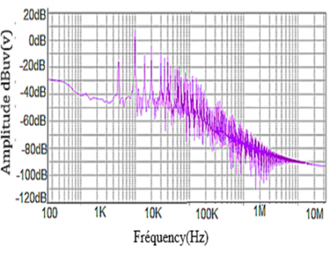
Figure 12. Output voltage spectrum of the rectifier-chopper association: (a) Simulation results, (b) Experimental results
Figure 12 shows the frequency results of the voltage at the output of the chopper obtained by simulation and by experiment.
The simulation frequency results at the rectifier output and those of the experiment present clear resonance peaks of interferences at a frequency of 10 kHz; these will be minimized towards the high frequencies.
5.3 Study of interferences in common mode
Common mode interferences are measured in order to compare them with the simulation results. The frequency variation graphs (current in common mode) presented in Figure 13 are obtained by simulation and by experimental measurements.
Figure 13 presents the current spectrum in common mode corresponding to the rectifier-chopper association. We note a concordance between the simulation and the experimental measurements, thus, a significant gain in the frequency of 15 kHz, at an amplitude equal to 60 dB, followed by a minimization of the interference towards the high frequencies.
5.4 Study of interferences in differential mode
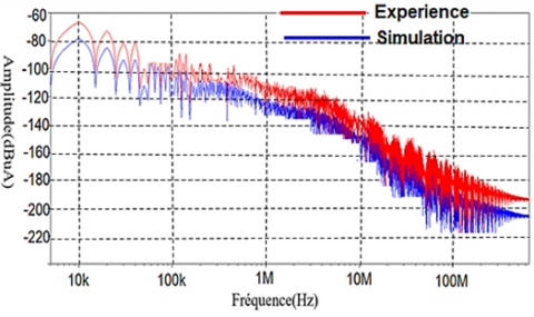
Figure 14 highlights the frequency variation of the current in differential mode, obtained by simulation and by experimental measurements.
The spectrum of the current in differential mode corresponding to the rectifier-chopper association is presented in Figure 14, where we notice an important level of the spectrum from –108 dBµA, for a resonance peak at a frequency of 150 kHz. Then, a slight minimization of the disturbance is observed towards the HF.
By comparing the results of the current spectrum of the two modes, it is noted that the spectrum of the current of common mode is very high compared to the current of the differential mode.
In order to minimize the effect of the common mode current on that of the differential mode, in practice, the semiconductor radiators and the ground plane of the load are isolated from the ground plane of the converter. In reality, the behavior of the load at high frequencies requires a more complex analysis of the propagation paths of EMI [17].
Figure 13. Current spectrum in common mode of the rectifier-chopper association
Figure 14. Current spectrum in differential mode of the rectifier-chopper association
The commutation cell in static converters generates differential and common mode interferences, which is a real problem in electrical systems. The present study determined the importance of these interferences based on the use of simulation and experimental results. A quantification of the interferences is performed in common and differential modes with the association of the single-phase rectifier and the serial chopper.
It has been proved practically that the interferences in the common mode are very high compared to the those in differential mode. This requires the use of other methods in order to reduce or eliminate these types of interferences, and this will be approached in future works.
|
EMC |
Electromagnetic compatibility |
|
EMI |
Electromagnetic interferences |
|
LISN |
Line Impedance Stabilization Network |
|
iDM |
Current of differential mode |
|
iCM |
Current of common mode |
|
Fbridge(t) |
The interferences to the rectifier over a half-period of the network signal |
|
FDM(t) |
The interference in differential mode of the converter over one chopping period |
|
FCM(t) |
The interference in common mode of the converter over one chopping period |
[1] Costa, F., Vollaire, C. (2008). Caractéristiques et évolution du bruit électromagnétique dans les dispositifs d’alimentation embarqués sur aéronef. Congrès CEM 08, p.8.
[2] Moreau, M. (2009). Modélisation haute fréquence des convertisseurs d’énergie. Application à l’étude des émissions conduites vers le réseau. PHD Thesis, Electrical Engineering, Central School of Lille-France.
[3] Chikhi, N., Bendaoud, A. (2019). Evaluation of conducted disturbances generated by the chopper-rectifier association propagating to the electrical network, European Journal of Electrical Engineering, 21(1): 1-6. https://doi.org/10.18280/ejee.210101
[4] Baghdadi, B. (2020). Etude des Perturbations Electromagnétiques Conduites dans un Réseau constitué de Convertisseurs Statiques DC/DC. Thèse de Doctorat de l’Université Djilali Liabes De Sidi Bel-Abbes.
[5] Benhadda, N., Bendaoud, A., Chikhi, N. (2018). A conducted EMI noise prediction in DC/DC converter using a frequency-domain approach. Elektrotehniški Vestnik Journal, 85(3): 103-108.
[6] Jettanasen, C. (2008). Modélisation par approche quadripolaire des courants de mode commun dans les associations convertisseurs-machines en aéronautique; optimisation du filtrage. Thèse de l’Ecole Centrale de Lyon, Spécialité génie Electrique.
[7] Costa, F. (2010). Compatibilité électromagnétique CEM - présentation générale. Techniques de l’ingénieur Compatibilité électromagnétique dans les systèmes électroniques.
[8] Delaballe, J. (2001). Cahier technique n. 149 - la CEM: la compatibilité électromagnétique. Rapport technique, Schneider Electric.
[9] Fakhfakh, L., Amous, A. (2016). New simplified model for predicting conducted EMI in DC/DC converters. Electrical Engineering, 99(3): 1087-1097. http://dx.doi.org/10.1007/s00202-016-0474-2
[10] Fakhfakh, L., Alahal, A., Amous, A. (2016). Fast modeling of conducted EMI phenomena using improved classical models. 2016 Asia-Pacific International Symposium on Electromagnetic Compatibility (APEMC), Shenzhen, China. http://dx.doi.org/10.1109/APEMC.2016.7522795
[11] Santos, V.D. (2019). Modélisation des émissions conduites de mode commun d'une chaîne électromécanique: Optimisation paramétrique de l'ensemble convertisseur filtres sous contraintes CEM. Thèse de Institut National Polytechnique de Toulouse, Spécialité génie Electrique.
[12] Miloudi, M., Bendaoud, A., Miloudi, H. (2017). Common and differential modes of conducted electromagnetic interference in switching power converters. Revue Roumaine Science Technique – Électrotechnique. et Énergétique, 62(3): 246-251.
[13] Benazza, B., Bendaoud, A., Reineix, A., Dafif, O., Slimani, H. (2019). Experimental study of the behaviour of the crosstalk of shielded or untwisted-pair cables in high frequency. Serbian Journal of Electrical Engineering, 16(3): 311-324. https://doi.org/10.2298/SJEE1903311B
[14] Slimani, H., Bendaoud, A., Reguig, J., Dafif, O. (2019). Experimental study of electromagnetic coupling between two transmission lines.19th International Symposium on Electromagnetic Fields in Mechatronics, Electrical and Electronic Engineering (ISEF), Nancy, France, pp. 1-2. https://doi.org/10.1109/ISEF45929.2019.9097073
[15] Di Piazza, M.C., Ragusa, A., Vitale, G. (2009). Design of grid-side electromagnetic interference filters in AC motor drives with motor-side common mode active compensation. IEEE Transactions on Electromagnetic Compatibility, 51(3): 673-682. https://doi.org/10.1109/TEMC.2009.2025595
[16] Miloudi, H., Bendaoud, A., Miloudi, M. (2017). A method for modeling a common-mode impedance for the AC motor. Elektrotehniški Vestnik Journal, 84(5): 241-246.
[17] Hrigua, S., Costa, F., Revol, B., Gautier, C. (2012). Nouvelle méthode d'analyse des interférences électromagnétiques (IEM) dans les convertisseurs statiques. 14ème édition de la Conférence Electronique de Puissance du Futur Bordeaux: 5-7 juillet 2012, Bordeaux, France.
[18] Idir, N. (2016). CEM en Électronique de Puissance: Convertisseurs Statiques Propres. Quatrièmes Journées d’Etude. Réseaux Electriques, Haute Tension et Compatibilité Electromagnétique. REHTCE’2016, 7-9 novembre 2016, Sidi bel-Abbès.
[19] Slimani, H., Bendaoud, A., Reguig, A. (2017). Measuring and reducing of harmonic pollution using rapid prototyping. European Journal of Electrical Engineering (EJEE), 19(3-4): 221-234. http://dx.doi.org/10.3166/ejee.19.221-234
[20] Ales, A., Gouichiche, Z., Karouche, B., Moussaoui, D., Schanen, J.L., Roudet, J. (2015). The accurate input impedances of a DC-DC converters connected to the network. IEEE 15th International Conference on Environment and Electrical Engineering (EEEIC), Rome, Italy, pp. 331-336. http://dx.doi.org/10.1109/EEEIC.2015.7165183
[21] Wang, S. (2002). Characterization and cancellation of high-frequency parasitics for EMI filters and noise separators in power electronics applications. Thèse de Doctorat, Faculté de l'Institut polytechnique de Virginie.
[22] Martin, C. (2005). Vers une méthodologie de conception des interconnexions pour les dispositifs de l'Electronique de Puissance. Thèse de doctorat, Université de Grenoble.