Awatif Nadia* | Md. Sanwar Hossain | Md. Mehedi Hasan | Khondoker Ziaul Islam | Shahajan Miah
© 2021 IIETA. This article is published by IIETA and is licensed under the CC BY 4.0 license (http://creativecommons.org/licenses/by/4.0/).
OPEN ACCESS
In the integrated power system network uncertainty can occur at any time. The transmission reliability (TRM) margin is the amount of transmission capacity that guarantees that the transmission network is protected from instability in the operating state of the system. The calculation of the available transfer capacity (ATC) of the transmission reliability margin should be included in a deregulated power system to ensure that the transmission network is safe within a fair range of uncertainties that arise during the power transfer. However, the TRM is conserved as a reliability margin to reflect the unpredictability of the operation of the electric system. Besides, the system operator (SO) utilizes the TRM value during unreliability by adjusting the ATC value some amount up or down to account for errors in data and uncertainty in the model. This paper describes a technique for TRM estimation by modified DCQ load flow method considering VAR transfer distribution factor. The main focus of this study is to get a new approach to determine TRM by incorporating with ATCQ considered reactive power and sensitivity w.r.t ATC considered voltage magnitude. This technique is applied to the IEEE 6 bus system, and results are compared with previous results for validation. The technique leads to more exact and secure estimates of transmission reliability margin.
transmission reliability margin, available transfer capability, DCQ load flow, sensitivity, reactive power
Transmission Reliability Margin is a function, which is always varying with time. Moreover, system reliability means the system should be able to perform decently under the desired conditions over some time [1, 2]. ATC can work as an indicator to increase the power transfer after the base flow within the inter-area net without hazarding system security; if its rated value falls for any contingency then TRM accounts for that inherent unpredictability in the system. The use of TRM permits the market to optimize the web, rather than face persistent hourly reduction. Determination of TRM should embody with ATC to assure a large amount of uncertainty. The Enumeration method, Monte Carlo simulation, stochastic response surface method (SRSM) help to estimate TRM with a less computational cost. The implication of considering ATC in TRM determination to ensure continuous power transfer during any kind of disruptions. Moreover, various techniques have been proposed for computation TRM and ATC [3-15]. DC power flow method considered for active power flow rather than reactive power but in a transmission network voltage level needs to keep stable otherwise over-voltage or voltage collapse will happen easily; for this reason, VAR is essential to control the system in a tolerable margin of security and authenticity. A DCQF model is developed with a proposed iterative QF model for compensating the pure VAR market [16]. The errors of ATC computation by linear methods can be decreased by inserting reactive power. Besides, maintaining the whole system at an acceptable margin as well as balancing energy, reactive power is required and this is used to determine ATC [17]. The state of uncertainty for each transaction is known as sensitivity and can be computed for far-ranging parameters by DC/AC load flow [18-20]. Shapley's approach to cooperative game theory is used for transmission usage cost allocation [21]. To maximize total transfer capability in Central-East-Europe power system investigates the use of specific FACTS devices and WAMS systems [22]. A configuration is investigated to control the voltage drop across the line by controlling the reactive power flow in the radial line [23].
Improvement in losses estimation and ATC calculation, considering dynamic transmission lines rating, instead of static rating need to improve which is discussed in this paper [24]. In paper [25, 26], a bi-level optimization framework is formulated for the evaluation of ATC as well as a review on ATC calculation. An algorithm is developed to determine ATC for generating a group of future wind generation scenarios [27]. Design a probabilistic available transfer capability (PATC) model that considered uncertainties and static security constraints [28]. Moreover, operating principles and applications of various FACTS devices for enhancing the ATC and power transfer capability (PTC) are discussed [29]. A new Cold-Start model that does not depend on jeopardizing assumption, as well as the effect of reactive loads on phase angles, is considered and the balanced equation for reactive power is also reflected in this model [30]. Unified Power Flow Controller (UPFC) is used to enhance the ATC in transmission line for IEEE-5 bus system [31]. A methodology known as BRAVO (Balanced Reliability-Aware Voltage Optimization) is used for reliability awareness. This is aided by a multi-core simulation structure that blends performance, power, and reliability modeling capability [32]. With the advancement of modern technology [33-39], an effective method is highly desirable for calculating the transmission reliability margin.
In this paper, TRM is calculated by modified DCQ load flow method to consider the VAR-voltage phenomenon for both Normal and Binomial distributions. In most of the previous work, ATC is calculated for the DC load flow method besides considered the only real power in the technique which is not very worthwhile to understand the voltage changing phenomena. Paradoxically, reactive power also flows through the line and VAR plays a vital role to balance the network by controlling voltage level. For this reason, this factor needs to focus on determining the ATC; this work represents a technique to calculate ATC considered reactive power. Besides, sensitivity is determining for transfer capability in previous cases; in this paper, sensitivity is calculated for ATC because it will reveal the weakness of the system which parameter has more impact on the system and which is not. Additionally, the change in VAR flow affects the voltage level greatly rather than any other parameters. For this reason, sensitivity w.r.t ATC is calculated for the voltage parameter. Besides, previously TRM is determined for many distinct approaches and Normal distribution but not for the DCQ method so, the effect on the margin for changing the voltage level for each transaction and both Normal and Binomial distribution is described here. Moreover, the rest of the paper is arranged in the following manner. In Section 2, the whole proposed technique is discussed. Section 3 presents TRM computation for the 6-bus case system. Validation and conclusion are discussed in Sections 4 and 5 respectively.
2.1 ATCQ determination by DCQTDFs method
Power flow from a seller bus to a buyer bus is called a transaction. A physical connection between zones or power systems is known as flow-gates. The power transfer distribution factors (PTDF) ensures that the transactions between zones do not jeopardize network operation by an imbalance on a flow-gate. It also represents the relationship between the transaction and the flow through a line. PTDFs calculated using DC load flow are known as DCPTDFs; for reactive power named as DCQTDF. In the DCQTDF method active power generations, demands, and voltage angles of all buses, resistance of all transmission lines assume zero. In this paper, the voltage magnitudes of a bus are considered, to see the effect of sensitivity. DC load flow for VAR proceeds as follows:
a) Calculate Ybus matrix from given bus data. Separate the imaginary part of the Ybus matrix. After that, calculate the susceptance matrix B, curtailed 1x1 in the matrix because the first bus is the reference bus.
b) Determine the reactive power flow through each line in the system (Qsch) [16]. Calculate voltage magnitudes for each bus except reference bus which is considered as 1.05 p.u,
$Q^{s c h}=Q_{g}-Q_{d}$ (1)
where, Qg and Qd are the reactive power of the generator and load buses respectively.
$V_{n}=B_{x} \times V_{s l}+Q^{s h}$ (2)
where, Bx is the last column of the bus susceptance matrix B and Vsl is the slack bus magnitude.
$V_{n e w}=X \times V_{n}$ (3)
where, X is the inverse of the bus susceptance matrix B. Finally, Vnew gives the voltage magnitudes from bus 2 to bus 6 for the 6-bus system.
c) Now, Calculate reactive power flows (Qo and Qn) for each transaction (t). Qo is calculated from the given voltage magnitude for the particular system and Qn is calculated from the estimated new voltage (Vnew) [16]:
$Q_{o}^{t}=\left(-B_{i j} \times \Delta V_{o}\right)$ (4)
$Q_{n}^{t}=\left(-B_{i j} \times \Delta V_{N}\right)$ (5)
where, Bij is the negative value from the susceptance matrix for ij line for a particular transaction (t).
$\Delta V_{o}=\left(V_{j}-V_{i}\right)$ (6)
$\Delta V_{N}=\left(V_{\text {new }}^{j}-V_{\text {nev }}^{i}\right)$ (7)
where, Vj and Vi are the given voltage magnitudes of bus j and i respectively, and $V_{\text {new }}^{i}$ are the new bus voltage magnitudes calculated from Eq. (3).
d) Now, DC VAR transfer distribution factors (DCQTDFs) are calculated from the following equation for a transaction (zone M→zone N) that flows through a transmission line (bus i→bus j).
$D C Q T D F_{i j, M N}=\frac{\left(Q_{n}^{t}-Q_{o}^{t}\right)}{L L_{\max }}$ (8)
where, LLmax is the maximum MVA flow through each line.
e) Calculate ATC for each transaction [17]:
If DCQTDFij,MN<0 then,
$A T C Q_{M N}=\min \left(\frac{-Q_{o}-L L_{\max }}{D C Q T D F_{i j, M N}}\right)$ (9)
If DCQTDFij,MN>0 then,
$A T C Q_{M N}=\min \left(\frac{Q_{o}-L L_{\max }}{D C Q T D F_{i j, M N}}\right)$ (10)
2.2 Calculation of sensitivity
For sensitivity calculation increase the voltage magnitudes by 5% of any bus, in this paper, one PV (bus 2) and one PQ (bus 5) bus are considered. The whole calculation is described below:
Increase voltage magnitude by 5% of PV bus 2 and calculated new $\Delta V_{o}$ and $\Delta V_{N}$; then put these values in Eqns. (6) and (7) respectively to get the new VAR flow as well as new ATCQ for each transaction, so the sensitivity is [15]:
$\frac{\partial A T C Q}{\partial V}=\frac{\Delta A T C Q}{\Delta V}$ (11)
where,
$\Delta V=\left(V_{\text {new }}-V_{\text {old }}\right)$ (12)
$\Delta A T C Q=\left(A T C Q_{\text {new }}-A T C Q_{\text {old }}\right)$ (13)
2.3 Calculation of TRM for normal distribution
Now, discrete random variables need to determine the mean, variance, and standard deviation for each transaction respectively; here the sensitivity of load and line admittances for each transaction is the discrete random variables.
Mean,
$\mu=E(x)=\sum_{i=1}^{v} x_{i} c_{i}^{2} p_{i}$ (14)
where, xl is the random variable 1,…,v, for this paper, and it’s the sensitivity; pi is the probability of that random variable; ci is the parameter distribution; for this paper the parameter is voltage and for that ci=0.05.
Variance,
$\sigma^{2}=E\left(x^{2}\right)-E^{2}(x)$ (15)
Standard deviation,
$\sigma=\sqrt{E\left(x^{2}\right)-E^{2}(x)}$ (16)
Calculate TRM [3] using Eq. (17):
$T R M=U \sigma$ (17)
Finally, these sensitivity values will be used together with a certain number (U) which is derived from the probability random function of a normal random variable to calculate the TRM. The considered values of U are 1.96 and 2.57 for 95% and 99% probability, respectively [3].
2.4 Calculation of TRM for the binomial distribution
To calculate TRM for binomial distribution first need to determine the probability density function [37] for 95% and 99% probability.
$\% P D F={ }^{n} C_{r} s^{r} f^{n-r}$
where, n=number of samples, r=no. of success, s=probability of success, f=(1-s) probability of failure.
After that, need to calculate the Z-score for binomial distribution the formula for this is:
$Z=\frac{k-\mu}{\sigma}$
where, Mean, μ=ns; Variance, σ2=nsf, Standard Deviation, $\sigma=\sqrt{n s f}$, k is the number of successes from the total number of samples.
Now, for determining TRM need to recalculate the standard deviation, $\sigma_{T R M}=\sqrt{n s f x_{i} c_{i}}$; xi and ci as the same as for normal distribution.
$T R M=Z \sigma_{T R M}$ (18)
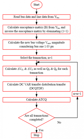
The algorithm of the proposed technique is presented in Figures 1 and 2. The determination of ATCQ is presented in Figure 1. In this approach first need to determine the Ybus then calculate the inverse susceptance matrix as well as the new bus voltage magnitude. After that, calculate the change in voltage magnitude, DCQTDFs, and ATCQ for each transaction. The whole process repeats until all transactions are completed. Now, the determination of TRM is shown in Figure 2. For each transaction utilize those calculated ATCQ values for sensitivity calculation. After that, determine to mean, variance, and S.D for the discrete random variable. Finally, use the formulas from Eqns. (17) and (18) to calculate TRM for Normal and Binomial distribution.
Figure 1. Flow chart of ATCQ determination by DCQ load flow
Figure 2. Flow chart of TRM determination by DCQ load flow
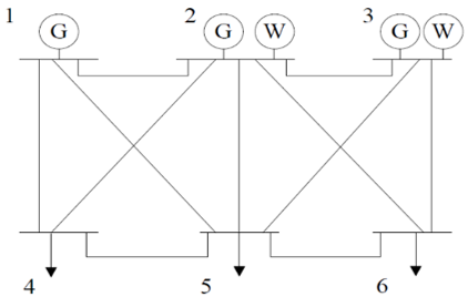
IEEE 6 bus system is shown in Figure 3, which consists of three sellers (generator) buses (buses 1, 2, and 3), three buyers (load) buses (buses 4, 5, and 6), and connected by eleven transmission lines. In this paper, nine transaction paths are considered besides two transmission lines (2-6 and 3-4) are not directly connected but considered as (1-5 to 5-6) for 2-6 and (2-3 to 2-4) for 3-4 lines respectively. All bus and line data were selected from the paper [11]. Tables 1 and 2 present the bus and branch data for the standard IEEE-6 bus system.
Table 3 presents the calculated ATCQ results for the base case, and the other two cases increase voltage magnitude for bus-2 and bus-5 and recalculate ATCQ. The results affect only (2-4, 2-5 & 2-6) transactions when the increased voltage level for bus-2 as well as for bus-5 affects the (1-5, 2-5 & 3-5) transactions.
Hence, it can state that for the DCQ load flow method, if any changes happen in one point only those lines will be affected which are connected to that point. Besides, sensitivity is also calculated for those transactions and for two types of buses (one is PV bus-2 and another is PQ bus-5). If the voltage level increases for the PV bus it increases the power transfer capability and for the PQ bus, it decreases the transfer. In PQ bus 5 real and reactive power are fixed, so if the voltage level increases then the ATCQ values are decreased but for PV bus 2 increases the recalculated ATCQ values because of the Ferranti effect. Tables 4 and 5, show the sensitivity and TRM results using the proposed technique for 95% and 99% probability of uncertainty for Normal and Binomial distributions respectively. For the generator bus, the sensitivity values are positive and for the load bus, it's negative and in these tables, only three transactions are taken because in Table 3 ATCQ values are affected only for these three transactions. The Binomial distribution is preferable for discrete random variables, for this reason, it chooses for this DCQ modified flow method and compares with the Normal distribution. Even though there is not much difference in the values of TRM; the main focus is that TRM can calculate by the DCQ load flow method for both probability distributions.
|
T14 |
Transaction from bus 1 to bus 4 |
|
T15 |
Transaction from bus 1 to bus 5 |
|
T16 |
Transaction from bus 1 to bus 6 |
|
T24 |
Transaction from bus 2 to bus 4 |
|
T25 |
Transaction from bus 2 to bus 5 |
|
T26 |
Transaction from bus 2 to bus 6 |
|
T34 |
Transaction from bus 3 to bus 4 |
|
T35 |
Transaction from bus 3 to bus 5 |
|
T36 |
Transaction from bus 3 to bus 6 |
Figure 3. IEEE 6 bus system [11]
Table 1. Bus data
|
Bus No. |
Bus Type |
Voltage magnitude (p.u) |
Real power generation (MW) |
Real power load (MW) |
Reactive power load (MVAR) |
|
1 |
SB |
1.05 |
0 |
0 |
0 |
|
2 |
PV |
1.05 |
50 |
0 |
0 |
|
3 |
PV |
1.07 |
60 |
0 |
0 |
|
4 |
PQ |
1 |
- |
70 |
70 |
|
5 |
PQ |
1 |
- |
70 |
70 |
|
6 |
PQ |
1 |
- |
70 |
70 |
Table 2. Branch data
|
Line No. |
Bus No. From-To |
Resistance (p.u) |
Reactance (p.u) |
Total line charging susceptance (p.u) |
Maximum Apparent power capacity (MVA) |
|
1 |
1-2 |
0.1 |
0.2 |
0.04 |
40 |
|
2 |
1-4 |
0.05 |
0.2 |
0.04 |
60 |
|
3 |
1-5 |
0.08 |
0.3 |
0.06 |
40 |
|
4 |
1-6 |
0.17 |
0.4 |
0.06 |
130 |
|
5 |
2-3 |
0.05 |
0.25 |
0.06 |
40 |
|
6 |
2-4 |
0.05 |
0.1 |
0.02 |
80 |
|
7 |
2-5 |
0.1 |
0.3 |
0.04 |
30 |
|
8 |
2-6 |
0.07 |
0.2 |
0.05 |
90 |
|
9 |
3-4 |
0.1 |
0.35 |
0.05 |
120 |
|
10 |
3-5 |
0.12 |
0.26 |
0.05 |
70 |
|
11 |
3-6 |
0.02 |
0.1 |
0.02 |
90 |
|
12 |
4-5 |
0.2 |
0.4 |
0.08 |
20 |
|
13 |
5-6 |
0.1 |
0.3 |
0.06 |
40 |
Table 3. ATCQ results
|
Transactions |
ATCQ values |
||
|
Base |
PV 2 |
PQ 5 |
|
|
T14 |
95.83 |
95.83 |
95.83 |
|
T15 |
105.895 |
105.895 |
79.77 |
|
T16 |
420.5 |
420.5 |
420.5 |
|
T24 |
137.73 |
195.6 |
137.73 |
|
T25 |
133.58 |
183.22 |
85.7 |
|
T26 |
365.35 |
463 |
365.35 |
|
T34 |
682.52 |
682.5 |
682.5 |
|
T35 |
334.06 |
334.06 |
256.71 |
|
T36 |
297.22 |
297.22 |
297.22 |
Table 4. TRM results for normal distribution
|
Transaction |
Sensitivity |
TRM |
Transaction |
Sensitivity |
TRM |
||
|
|
PV 2 |
95% |
99% |
|
PQ 5 |
95% |
99% |
|
T24 |
8.35 |
0.79 |
1.07 |
T15 |
-3.9 |
0.37 |
0.49 |
|
T25 |
7.2 |
0.69 |
0.92 |
T25 |
-7.3 |
0.69 |
0.93 |
|
T26 |
14.1 |
1.35 |
1.8 |
T35 |
-11.7 |
1.12 |
1.49 |
Table 5. TRM results for the binomial distribution
|
Transaction |
Sensitivity |
TRM |
Transaction |
Sensitivity |
TRM |
||
|
|
PV 2 |
95% |
99% |
|
PQ 5 |
95% |
99% |
|
T24 |
8.35 |
0.63 |
0.65 |
T15 |
-3.9 |
0.43 |
0.44 |
|
T25 |
7.2 |
0.58 |
0.59 |
T25 |
-7.3 |
0.59 |
0.60 |
|
T26 |
14.1 |
0.82 |
0.84 |
T35 |
-11.7 |
0.75 |
0.76 |
TRM results obtained from the proposed technique are compared with the results of the papers [3, 7] which are quite close, and it's done by the DCQ load flow method which is very flexible and much easier than the former methods. Tables 4 and 5 present the TRM values for 95% and 99% probability of failure and show that a rise in the probability of failure, also rise the TRM which proves the system reliability. Tables 6 and 7 present the validation of this work. It is clear that the proposed approach yields findings that are identical to those previously reported. Figure 4 and Figure 5 represent the TRM values for two distinct probability distribution (Normal and Binomial) besides, these are the validation chart; compared the proposed technique result with previous techniques result.
Table 6. Validation of TRM results for normal distribution
|
Probability of uncertainty |
95% |
99% |
|
Proposed Technique |
0.69 |
0.93 |
|
TRM formula |
0.775 |
1.09 |
|
Monte Carlo |
0.785 |
1.108 |
Table 7. Validation of TRM results for binomial distribution
|
Probability of uncertainty |
95% |
99% |
|
Proposed Technique |
0.82 |
0.84 |
|
TRM formula |
0.775 |
1.09 |
|
Monte Carlo |
0.785 |
1.108 |
Figure 4. Validation of TRM values for normal distribution
Figure 5. Validation of TRM values for binomial distribution
Reactive power plays a vital role for system reliability purposes especially for voltage security margin because in a power system network voltage stability is influenced by VAR support at various locations. The contribution of this paper is to develop a new technique to determine TRM by DCQ load flow method considered ATCQ and voltage parameter for sensitivity calculation. The proposed technique compared its results with other techniques for its validation. The validation presents that the results of the proposed technique are closed to the previous one.
[1] Billiton, R. (1970). Power system reliability evaluation. Taylor & Francis, Technology & Engineering, 46(1): 15-23. https://doi.org/10.1016/0951-8320(94)90044-2
[2] Bazovsky, I. (1962). Reliability: Theory and practice. Prentice-Hall International, London, 66(619): 465-465. https://doi.org/10.1017/s0368393100077051
[3] Hang, J., Dobson, I., Alvarado, F. (2004). Quantifying transmission reliability margin. International Journal of Electrical Power & Energy Systems, 26(9): 697-702. https://doi.org/10.1016/s0142-0615(04)00071-7
[4] Zaini, R.H., Othman, M.M., Musirin, I., Mohamed, A., Hussain, A. (2010). Determination of transmission reliability margin considering uncertainties of system operating condition and transmission line outage. European Transactions on Electrical Power, 21(1): 380-397. https:// doi.org/10.1002/etep.448
[5] Sauer, P.W. (1998). Alternatives for calculating transmission reliability margin (TRM) in available transfer capability (ATC). Proceedings of the Thirty-First Hawaii International Conference on System Sciences, Kohala Coast, HI, USA. https://doi.org/10.1109/hicss.1998.656069
[6] Sauer, P.W. (1997). Technical challenges of computing available transfer capability (ATC) in electric power systems. Proceedings of the Thirtieth Hawaii International Conference on System Sciences, Wailea, HI, USA. https://doi.org/10.1109/hicss.1997.663220
[7] Sun, X., Chen, J., Zhu, Q., Shi, D., Li, Y.H., Duan, X. (2016). Assessment of transmission reliability margin using stochastic response surface method. IEEE Power and Energy Society General Meeting (PESGM), Boston, MA, USA. https://doi.org/10.1109/pesgm.2016.7741476
[8] Othman, M.M., Mohamed, A., Hussain, A. (2006). Determination of available transfer capability incorporating transmission reliability margin. IEEE International Power and Energy Conference, Putra Jaya, Malaysia. https://doi.org/10.1109/pecon.2006.346643
[9] Kumar, A., Kumar, J. (2012). Comparison of UPFC and SEN transformer for ATC enhancement in restructured electricity markets. International Journal of Electrical Power & Energy Systems, 41(1): 96–104. https://doi.org/10.1016/j.ijepes.2012.03.019
[10] Venkatesh, D.P., Gnanadass, R., Padhy, D.N.P. (2004). Available transfer capability determination using power transfer distribution factors. International Journal of Emerging Electric Power Systems, 1(2): 1009. https://doi.org/10.2202/1553-779x.1009
[11] Christie, R.D., Wollenberg, B.F., Wangensteen, I. (2000). Transmission management in the deregulated environment. Proceedings of the IEEE, 88(2): 170-195. https://doi.org/ 10.1109/5.823997
[12] Kumar, R., Gupta, S.C., Khan, B. (2013). Power transfer distribution factor estimate using DC load flow method. International Journal of Advanced Electrical and Electronics Engineering (IJAEEE), 2(6): 155-159.
[13] Šošić, D., Škokljev, I. (2013). Evolutionary algorithm for calculating available transfer capability. Journal of Electrical Engineering, 64(5): 1-7. https://doi.org/10.2478/jee-2013-0042
[14] Kumar, A., Srivastava, S.C., Singh, S.N. (2004). Available transfer capability (ATC) determination in a competitive electricity market using AC distribution factors. Electric Power Components and Systems, 32(9): 927-939. https://doi.org/10.1080/15325000490253623
[15] Dobson, I., Greene, S., Rajaraman, R., DeMarco, C.L., Alvarado, F.L., Glavic, M., Zimmerman, R. (2001). Electric power transfer capability: Concepts, applications, sensitivity and uncertainty. PSERC Publication, (01-34).
[16] Beagam, K.S.H., Jayashree, R., Khan, M.A. (2017). A new DC power flow model for Q flow analysis for use in reactive power market. Engineering Science and Technology, an International Journal, 20(2): 721-729. https://doi.org/10.1016/j.jestch.2016.10.018
[17] Grijalva, S., Sauer, P.W. (1999). Reactive power considerations in linear ATC computation. Proceedings of the 32nd Annual Hawaii International Conference on Systems Sciences. HICSS-32. https://doi:org/10.1109/hicss.1999.772870
[18] Greene, S., Dobson, I., Alvarado, F.L. (2002). Sensitivity of transfer capability margins with a fast formula. IEEE Transactions on Power Systems, 17(1): 34-40. https://doi.org/10.1109/59.982190.
[19] Ghawghawe, N.D., Thakre, K.L. (2006). Application of power flow sensitivity analysis and PTDF for determination of ATC. International Conference on Power Electronic, Drives and Energy Systems, New Delhi, India, pp. 1-7. https://doi.org/10.1109/pedes.2006.344304
[20] Greene S., Dobson, I. (1998). Margin and sensitivity methods for security analysis of electric power systems. Ph.D. Thesis. ECE Department, University of Wisconsin, Madison, WI USA.
[21] Khare, S., Khan, B., Agnihotri, G. (2015). A Shapley value approach for transmission usage cost allocation under contingent restructured market. 2015 International Conference on Futuristic Trends on Computational Analysis and Knowledge Management (ABLAZE), Greater Noida, India. https://doi.org/10.1109/ablaze.2015.7154987
[22] Kolcun, M., Čonka, Z., Beňa, L., Kanálik, M., Medveď, D. (2016). Improvement of transmission capacity by FACTS devices in central East Europe power system. IFAC-PapersOnLine, 49(27): 376-381. https://doi.org/10.1016/j.ifacol.2016.10.756
[23] Singh, A., Frei, T., Chokani, N., Abhari, R.S. (2016). Impact of unplanned power flows in interconnected transmission systems – Case study of central Eastern European region. Energy Policy, 91: 287-303. https://doi.org/10.1016/j.enpol.2016.01.006
[24] Mahmoudian, M., Yousefi, G.R. (2012). ATC improvement and losses estimation considering dynamic transmission line ratings. Iranian Conference on Electrical Engineering (ICEE2012), Tehran, Iran. https://doi.org/10.1109/iraniancee.2012.6292392
[25] Chen, H., Fang, X., Zhang, R., Jiang, T., Li, G., Li, F. (2017). Available transfer capability evaluation in a deregulated electricity market considering correlated wind power. IET Generation, Transmission & Distribution, 12(1): 53-61. https://doi.org/10.1049/iet-gtd.2016.1883
[26] Mohammed, O.O., Mustafa, M.W., Mohammed, D.S.S., Otuoze, A.O. (2019). Available transfer capability calculation methods: A comprehensive review. International Transactions on Electrical Energy Systems, 29(6): 1-24. https:// doi.org/10.1002/2050-7038.2846
[27] Du, P., Li, W., Ke, X., Lu, N., Ciniglio, O.A., Colburn, M., Anderson, P.M. (2015). Probabilistic-based available transfer capability assessment considering existing and future wind generation resources. IEEE Transactions on Sustainable Energy, 6(4): 1263-1271. https://doi.org/10.1109/tste.2015.2425354
[28] Wei, Z., Chen, S., Sun, G., Wang, D., Sun, Y., Zang, H. (2016). Probabilistic available transfer capability calculation considering static security constraints and uncertainties of electricity-gas integrated energy systems. Applied Energy, 167: 305-316. https://doi.org/10.1016/j.apenergy.2015.10.015
[29] Albatsh, F.M., Mekhilef, S., Ahmad, S., Mokhlis, H., Hassan, M.A. (2015). Enhancing power transfer capability through flexible AC transmission system devices: A review. Frontiers of Information Technology & Electronic Engineering, 16(8): 658-678. HTTPS://doi.ORG/10.1631/fitee.1500019
[30] Fatemi, S.M., Abedi, S., Gharehpetian, G.B., Hosseinian, S.H., Abedi, M. (2015). Introducing a novel DC power flow method with reactive power considerations. IEEE Transactions on Power Systems, 30(6): 3012-3023. https://doi.org/10.1109/tpwrs.2014.2368572
[31] Gupta, K., Khan, B., Mubeen, S.E. (2015). Available transfer capability enhancement by unified power flow controller. 2015 IEEE International Conference on Signal Processing, Informatics, Communication and Energy Systems (SPICES), Kozhikode, India. https://doi.org/10.1109/spices.2015.7091428
[32] Swaminathan, K., Chandramoorthy, N., Cher, C.Y., Bertran, R., Buyuktosunoglu, A., Bose, P. (2017). BRAVO: Balanced reliability-aware voltage optimization. IEEE International Symposium on High Performance Computer Architecture (HPCA), Austin, TX, USA. https://doi.org/10.1109/hpca.2017.56
[33] Hossain, M.S., Rahman, M., Sarker, M.T., Haque, M.E, Jahid, A. (2019). A smart IoT based system for monitoring and controlling the sub-station equipment. Internet of Things, 7(100085): 1-16. https://doi.org/10.1016/j.iot.2019.100085
[34] Haque, M.E., Asikuzzaman, M., Khan, I.U., Ra, I.H., Hossain, M.S., Shah, S.B.H. (2020). Comparative study of IoT-based topology maintenance protocol in a wireless sensor network for structural health monitoring. Remote Sensing, 12(15): 2358. https://doi.org/10.3390/rs12152358
[35] Hossain M.S., Jahid, A., Islam, K.Z., Alsharif, M.H., Rahman, M.F. (2020). Multi-objective optimum design of hybrid renewable energy system for sustainable energy supply to a green cellular networks. Sustainability, 12(9): 3536. https://doi.org/10.3390/su12093536
[36] Hossain, M.S., Rahman, M.F. (2020). Hybrid solar PV/Biomass powered energy efficient remote cellular base stations. International Journal of Renewable Energy Research (IJRER), 10(1): 329-342
[37] Nadia A., Chowdhury, A.H., Mahfuj, E., Hossain, M.S., Islam, K.Z., Rahman, M.I. (2020). Determination of transmission reliability margin using AC load flow. AIMS Energy, 8(4): 701-720. https://doi.org/10.3934/energy.2020.4.701
[38] Hossain, M.S, Jahid, A., Islam, K.Z., Alsharif, M.H., Rahman, K.M., Rahman, M.F., Hossain, M.F. (2020). Towards energy efficient load balancing for sustainable green wireless networks under optimal power supply. IEEE Access, 8(1): 200635-200654. https://doi.org/10.1109/ACCESS.2020.3035447
[39] Bin Othman, M.M., Mohamed, A., Hussain, A. (2008). Determination of transmission reliability margin using parametric bootstrap technique. IEEE Transactions on Power Systems, 23(4): 1689–1700. https://doi.org/10.1109/tpwrs.2008.2004734