Baoge Zhang* | Deyu Hong
© 2021 IIETA. This article is published by IIETA and is licensed under the CC BY 4.0 license (http://creativecommons.org/licenses/by/4.0/).
OPEN ACCESS
An improved single-phase unisolated grid-connected photovoltaic inverter topology is proposed to solve the common mode leakage current problem of unisolated grid-connected photovoltaic inverters. By analyzing the topology structure and voltage clamping principle of the improved inverter, the topology can maintain the same low input voltage as the full-bridge inverter, and ensure that the common-mode voltage in the continuation mode is clamped to the midpoint voltage of the bus, so as to effectively reduce the common-mode leakage current caused by the common-mode voltage suspension in the continuation mode. Moreover, the common-mode leakage current of the improved topology is smaller than that of the traditional H6-2D topology at similar conversion efficiency. The simulation results on MATLAB /Simulink platform show that the topology is feasible and effective.
common mode leakage current, single phase non-isolation, photovoltaic grid connection, topological structure, conversion efficiency
The topology of single-phase grid-connected photovoltaic (PV) inverters can be divided into two types: isolated type and non-isolated type according to whether the current is isolated. Isolated grid-connected PV inverters can form current isolation between PV modules and the power grid. However, they are large in size and have low efficiency [1, 2]. The unisolated PV grid-connected inverter has the advantages of small size, light weight, low cost and high efficiency. However, there is no transformer between the PV module and the power grid, resulting in current connection, so that the common-mode leakage current flows from the PV module to the power grid [3, 4], which increases the total harmonic distortion of grid-connected current, system loss, and even causes safety problems [5-8]. Therefore, the application of unisolated grid-connected PV inverters must meet strict safety standards [9, 10]. Single-phase non-isolated PV inverters at home and abroad widely use the traditional H-Bridge to realize the inverter function through the unipolar sinusoidal pulse width modulation (SPWM), but the common mode leakage current is inevitable [11]. Although the traditional H-Bridge has the ability to suppress common-mode leakage current through bipolar SPWM modulation, its two-stage output voltage makes the grid-connected current harmonic larger and requires a larger filter inductor [12]. The traditional H5 topology and the improved H6 topology reduce the common-mode leakage current through the method of DC decoupling. Due to the existence of switching junction capacitance, this method cannot completely disconnect the connection with the DC side, and the common-mode leakage current still exists [13-15]. Conventional H6-2D topology and HERIC topology reduce common-mode leakage current through AC decoupling, but additional common-mode filters are needed, which will increase the cost and power density of the inverter, and there are problems of diode reverse recovery [16, 17].
Based on the principle of common mode leakage current and H6-2D topology, an improved single-phase unisolated grid-connected PV inverter topology is proposed in this paper. Firstly, the traditional topology and the improved topology working methods are analyzed. Secondly, by analyzing the voltage clamp principle, the reason why the improved topology can effectively reduce the common mode leakage current is further explained. Finally, the traditional topology and the improved topology are compared, and the feasibility of the proposed topology is verified.
2.1 Common mode leakage current analysis
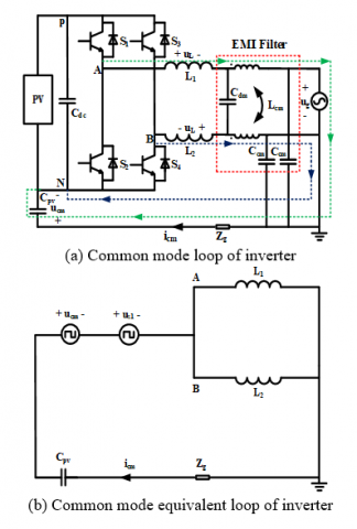
Isolation between the PV grid inverter and power grid due to no electrical isolation transformer, photovoltaic cells and parasitic capacitance between earth and therefore will form a parasitic capacitance between Cpv, filtering inductance L1, L2, and the earth of common mode resonant circuit, P and N is negative, the Cdc is DC bus capacitors, Cdm, Ccm and Lcm electromagnetic interference (EMI) filter. The high frequency action of the inverter switch will lead to changes in the common-mode voltage at both ends of the parasitic capacitor, which will form the common-mode leakage current icm in the circuit, and the parasitic capacitance value can reach 50-150 nF/kW. This is the generation mechanism of the common mode leakage current of the unisolated grid-connected PV inverter [18]. The common mode circuit of the transformerless PV inverter is shown in Figure 1(a). The parasitic capacitance to ground is ignored in the output of the inverter.
In the common-mode resonant loop shown in Figure 1 the loop equation as shown in Eq. (1) can be obtained according to Kirchhoff's voltage law, and common-mode voltage ucm and differential mode voltage udm can be obtained according to the further derivation of the definition as shown in Eq. (2) and Eq. (3) respectively [19].
Figure 1. Generation of common mode leakage current
$\left\{\begin{array}{l}u_{\mathrm{L}}+u_{\mathrm{g}}+u_{\mathrm{cm}}-u_{\mathrm{AN}}=0 \\ -u_{\mathrm{L}}+u_{\mathrm{cm}}-u_{\mathrm{BN}}=0\end{array}\right.$ (1)
$u_{\mathrm{cm}}=\frac{u_{\mathrm{AN}}+u_{\mathrm{BN}}}{2}$ (2)
$u_{\mathrm{dm}}=u_{\mathrm{AN}}-u_{\mathrm{BN}}$ (3)
$u_{\mathrm{s} 1}=\frac{u_{\mathrm{dm}}\left(L_{1}-L_{2}\right)}{2\left(L_{1}+L_{2}\right)}$ (4)
$\begin{aligned} u_{\mathrm{tcm}} &=u_{\mathrm{cm}}+\frac{u_{\mathrm{dm}}\left(L_{1}-L_{2}\right)}{2\left(L_{1}+L_{2}\right)} \\ &=\frac{u_{\mathrm{AN}}+u_{\mathrm{BN}}}{2}+\frac{\left(u_{\mathrm{AN}}-u_{\mathrm{BN}}\right)\left(L_{1}-L_{2}\right)}{2\left(L_{1}+L_{2}\right)} \end{aligned}$ (5)
$i_{\mathrm{cm}}=C_{\mathrm{PV}} \frac{d u_{\mathrm{cm}}}{d t}$ (6)
where, uL is the voltage at both ends of the filter inductor, ug is the voltage at the grid side, uAN and uBN are the output voltage of the inverter relative to the negative end N of the DC bus, us1 and utcm are the differential mode equivalent voltage source and the total equivalent common mode voltage, respectively.
Since the frequency of the switch tube is much higher than the frequency of the power grid, the power grid voltage source can be regarded as a short circuit. Then, using the Thevenin theorem, Figure 1(a) can be simplified to the common mode equivalent circuit of the inverter as shown in Figure 1(b). Through derivation, Eq. (4) can be obtained [20]. In single-phase unisolated grid-connected PV inverters, the inductance structure of grid-connected filter is divided into symmetrical and asymmetric conditions, which will have some influence on common mode voltage and lead to additional common mode leakage current. Therefore, the total equivalent common mode voltage needs to be calculated, as shown in Eq. (5). A symmetric filter inductance structure (L1=L2) is used in this paper. Then the common-mode voltage of the single-phase unisolated grid-connected PV inverter is shown in Eq. (2) and the common-mode leakage current is shown in Eq. (6).
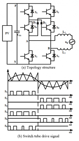
2.2 Traditional H6-2D topological analysis
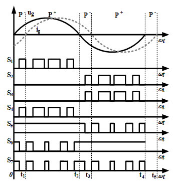
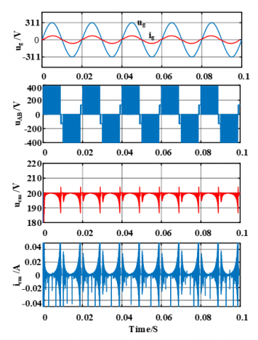
Figure 2(a) shows the traditional H6-2D topology without midpoint voltage clamp [20]. On the basis of the full bridge topology, two switches S5 and S6 are introduced into the middle of the left and right arms of the full bridge respectively, and at the same time, two fast recovery diodes D1 and D2 are connected to overcome the shortcomings of the H6-2D topology based on MOSFET switches [17]. (S1-S6 is IGBT switch tube). The switch tube drive signal for this topology is shown in Figure 2(b). In the positive half period, S1 and S4 switch at high frequency, while S5 is always in the on-state. When S1, S4, S5 on, the rest of the switch tube and diode off, for power transmission mode; When only S5 and diode D2 are on, it is in continuation mode. The S5 and S6 switches and the quick-recovery diodes provide a path to the zero-voltage continued current mode throughout the cycle.
Figure 2. Traditional topology
For a topology without midpoint voltage clamp, the common-mode voltage is 0.5 UPV (ucm = 0.5(uAN + uBN = 0.5(UPV + 0) = 0.5 UPV) during power transfer mode. However, during the continuous flow mode, the connection path between the PV module and the grid is disconnected. At this point, the inverter output terminals A and B are suspended relative to the DC side circuit, the common-mode voltage oscillates about 0.5 UPV during this period.
Table 1. Traditional topology common-mode and differential mode voltages
|
The positive half cycle |
The negative half cycle |
|||
|
Power transmission mode |
Stream mode |
Power transmission mode |
Stream mode |
|
|
Common mode voltage (V) |
0.5UPV |
0.5UPV (float) |
0.5UPV |
0.5UPV (float) |
|
Differential mode voltage (V) |
+UPV |
0 |
-UPV |
0 |
The common-mode and different-mode voltages of the traditional H6-2D topology are shown in Table 1.
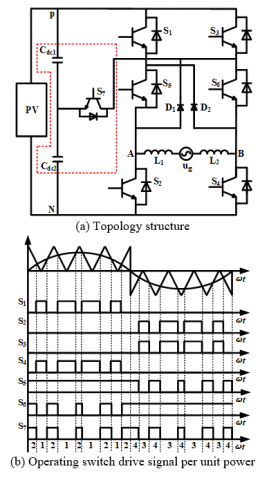
3.1 Unit power factor operation analysis
Figure 3. Improved topology
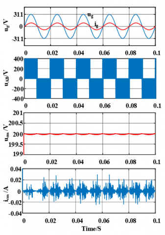
The improved topology is shown in Figure 3(a). An insulated-gate bipolar transistor (IGBT) is introduced, and the DC bus capacitance Cdc is divided into two series capacitors, Cdc1 and Cdc2, respectively. The nodes with two capacitors in series provide a midpoint voltage potential of the bus. D1 and D2 are quick recovery diodes. L1 and L2 are symmetrical grid-connected filter inductors. Figure 3(b) shows the switch drive signal of the improved topology. The improved topology can not only achieve AC-DC decoupling, but also effectively clamp the common-mode voltage ucm to the midpoint voltage of the bus during the continuation mode. but also effectively clamp the common-mode voltage ucm to the midpoint voltage of the bus during the continuation mode.
The common-mode and different-mode voltages of the improved topology are shown in Table 2. In one cycle of grid voltage, switch S5 is always in the conduction state within positive half cycle, and switch S6 is always in the conduction state within negative half cycle. The circuit has four operating modes.
Table 2. Improved topological common-mode and differential mode voltages
|
The positive half cycle |
The negative half cycle |
|||
|
Power transmission mode |
Stream mode |
Power transmission mode |
Stream mode |
|
|
Common mode voltage (V) |
0.5UPV |
0.5UPV |
0.5UPV |
0.5UPV |
|
Differential mode voltage (V) |
+UPV |
0 |
-UPV |
0 |
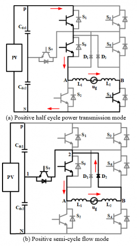
Mode 1: Power grid voltage is in positive half cycle, as shown in Figure 4(a). Switches S1, S4 and S5 are in on state, and the rest are in off state. The current flow path is: S1-S5-L1-ug-L2-S4. In this mode, point A is connected to the front end of PV cell through switch S1 and S5, so uAN =UPV; Point B is connected to the negative end of the PV cell through switch S4, so uBN = 0. The output voltage uAB = UPV can be obtained. The common mode voltage of the circuit in mode 1 is:
$u_{\mathrm{cm}}=\frac{u_{\mathrm{AN}}+u_{\mathrm{BN}}}{2}=\frac{U_{\mathrm{PV}}+0}{2}=\frac{U_{\mathrm{PV}}}{2}$ (7)
Mode 2: Power grid voltage is in positive half cycle, as shown in Figure 4(b), switch S1 and S4 are turned off simultaneously, quick recovery diode D2 is turned on, switch S5 is turned on, and clamp switch S7 is turned on. The current flow path is L1-ug-L2-D2-S5. The four points 1, 2, A and B are equipotential points, of which 1 is the midpoint potential point connected by two series capacitors. Point A is connected to point 1 through switch S5 and clamp switch S7, and the relative voltage of point N is clamped to half of the input voltage, uAN = 0.5 UPV; Point B is connected to point 1 by quick recovery diode D2 and clamp switch S7, similarly, uBN = 0.5 UPV. Output voltage uAB = 0. The common mode voltage of the circuit in mode 2 is:
$u_{\mathrm{cm}}=\frac{u_{\mathrm{AN}}+u_{\mathrm{BW}}}{2}=\frac{0.5 U_{\mathrm{PV}}+0.5 U_{\mathrm{PV}}}{2}=\frac{U_{\mathrm{PV}}}{2}$ (8)
Mode 3: The grid voltage is in a negative half cycle, as shown in Figure 4(c). Switches S2, S3 and S6 are in on state, while the other switches are in the off state. The current flow path is S3-S6-L2-ug-L1-S2. In this mode, point A is connected to the negative end of the PV cell through switch S2, uAN =0; Point B is connected to the front end of the PV cell through switches S3 and S6, uBN = UPV. The output voltage is uAB = -UPV. The common mode voltage of the circuit in mode 3 is:
$u_{\mathrm{cm}}=\frac{u_{\mathrm{AN}}+u_{\mathrm{BM}}}{2}=\frac{0+U_{\mathrm{PV}}}{2}=\frac{U_{\mathrm{PV}}}{2}$ (9)
Mode 4: The grid voltage is in a negative half cycle, as shown in Figure 4(d). Switches S2 and S3 are turned off at the same time. Quick recovery diode D1 is on, switch S6 is on, and clamp switch S7 is on. The current flow path is L2-ug-L1-D1-S6. The four points 1, 2, A and B are equipotential points, of which 1 is the midpoint potential point connected by two series capacitors. Point A is connected to point 1 by A quick recovery diode D1 and A clamp switch S7, and the voltage of point N is clamped to half of the input voltage, uAN = 0.5 UPV; Point B is connected to point 1 through switch S6 and clamp switch S7, similarly, uBN = 0.5 UPV. Output voltage uAB = 0. The common mode voltage of the circuit in mode 4 is:
$u_{\mathrm{cm}}=\frac{u_{\mathrm{AN}}+u_{\mathrm{BN}}}{2}=\frac{0.5 U_{\mathrm{PV}}+0.5 U_{\mathrm{PV}}}{2}=\frac{U_{\mathrm{PV}}}{2}$ (10)
Figure 4. An improved topology unit power factor operation analysis
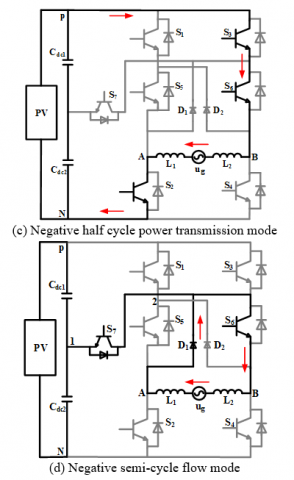
3.2 Reactive power operation analysis
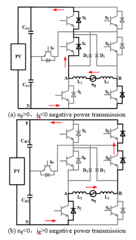
When the improved topology operates in the reactive operating mode, there are altogether six operating modes within a grid voltage cycle. Except for the four operating modes as shown in Figure 4, the other two operating modes work in the period of negative power transmission. At this time, the product of the instantaneous value of grid voltage and the instantaneous value of grid-connected current is negative. As shown in Figure 5, (t1-t2) and (t3-t4) are positive power transmission stages, and their working modes are Figure 4(a) mode 1 and Figure 4(c) mode 3, respectively. The working modes of (0-t1) and (t2-t3) are shown in Figure 6(a) and Figure 6(b), respectively.
Mode 5(0-t1): In this mode, S1, S4 and S5 are on state, the grid voltage zero crossing changes from negative to positive, and the grid-connected current remains negative. At this time, the grid-connected current is continued through the parallel diodes of S1, S4 and S5 to reduce the voltage drop, as shown in Figure 6(a). The voltage at the output of the inverter is shown in mode 1. The expression of common mode voltage is shown in Eq. (7).
Mode 6(t2-t3): In this mode, S2, S3 and S6 are on state, the zero point of the grid voltage changes from positive to negative, and the grid-connected current remains positive. At this time, the grid-connected current is continued through the parallel diodes of S2, S3 and S6 to reduce the voltage drop, as shown in Figure 6(b). The voltage at the output of the inverter as shown in mode 3. The expression of common mode voltage is shown in Eq. (9).
Figure 5. Reactive power running switch drive signal
Figure 6. Analysis of reactive power operation of improved topology
3.3 Voltage clamp analysis
In the whole grid cycle of the improved topology, if the voltage of the continuous-current loop is reduced, the voltage of the continuous-current loop is increased to 0.5 UPV through the reverse parallel diode of S7, as shown in Figure 7(a). Conversely, if the voltage in the continuation loop increases, the S7 turns on to reduce the voltage in the continuation loop to 0.5 UPV, as shown in Figure 7(b).
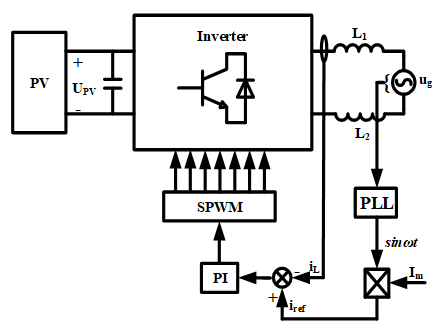
The control mode of the improved topology adopts the current loop control strategy. The output inductance current iL is sampled and differed from the reference current iref. The error signal is generated by PI controller to generate the modulation signal, and then the modulation signal is compared with the triangular carrier to obtain the drive signal of the switch tube. The control strategy is shown in Figure 8.
Figure 7. Positive half cycle voltage clamp
Figure 8. Positive half cycle voltage clamp
4.1 Simulation analysis
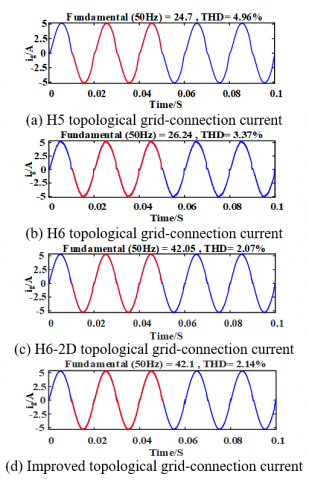
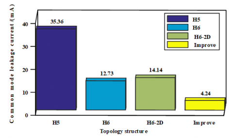
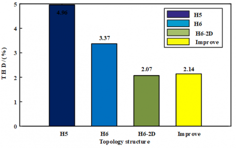
In order to verify the performance of the improved topology, the simulation models of H5 topology, H6 topology, H6-2D topology and the improved topology were built on MATLAB/Simulink platform, and the same control strategy was adopted for the four topologies. Firstly, the effective values of common mode leakage current of the four topologies were compared and analyzed through simulation, which were respectively about 35.36 mA, 12.73 mA, 14.14 mA and 4.24 mA, as shown in Figure 9. At the same time, the ig total harmonic distortion (THD) of the grid-connected current of the improved topology is 2.14%, which is better than that of H5 topology and H6 topology, and close to that of H6-2D topology, and has excellent grid-connected output characteristics as shown in Figure 10. From the comparative analysis of the four topologies, we can see that the improved topology can reduce the common mode leakage current more effectively than the other three topologies, and the output voltage uAB of the four topologies is three levels under unipolar modulation, which has good DC characteristics. The parasitic capacitance of the PV panel is 300 nF, and the other simulation parameters [3, 21] are shown in Table 3.
(a) H5 topology
(b) H6 topology
(c) H6-2D topology
(d) Improve topology
Figure 9. Common mode leakage current simulation analysis
Table 3. Simulation parameters
|
Parameter |
On behalf of the symbol |
Numerical |
|
Grid voltage/(V) |
ug |
220 |
|
Grid frequency/(Hz) |
fg |
50 |
|
Rated output/(kW) |
Pout |
3 |
|
DC side voltage/(V) |
UPV |
400 |
|
DC side capacitance/(µF) |
Cdc1, Cdc2 |
470 |
|
Filtering inductance/(mH) |
L1, L2 |
3 |
Figure 10. Analysis of total harmonic distortion of grid-connected current
4.2 Loss analysis
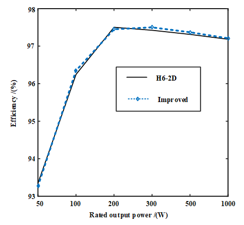
Figure 11. Comparison of topological efficiency
In the absence of line loss analysis and the same output power, the conversion efficiency of the improved topology and H6-2D topology is compared, as shown in Figure 11. Although the modified topology adds a power switch, the common-mode leakage caused by common-mode voltage suspension is more effectively reduced by voltage clamping at the midpoint of the busbar capacitor. Therefore, the conversion efficiency of the improved topology proposed in this paper is similar to that of H6-2D topology.
(a) Common mode leakage current data analysis
(b) Grid-connected current harmonic data analysis
Figure 12. Data analysis
The improved topology proposed in this paper can clamp the common-mode voltage in the continuous current mode to the midpoint voltage of the bus capacitance, thus solving the problem of common-mode voltage suspension and effectively, and reducing the common-mode leakage current. In addition, the topology has the following advantages:
This work was supported by the National Natural Science Foundation of China (Grant number: No. 61741508).
[1] Teodorescu, R., Liserre, M., Rodriguez, P. (2011). Grid converters for photovoltaic and wind power systems. Wiley-IEEE Press. https://doi.org/10.1002/9780470667057
[2] Kazmierkowski, M.P., Krishnan, R.F., Blaabjerg. (2002). Control in Power Electronics: Selected Problems. Academic Press.
[3] Cha, W.J., Kim, K.T., Cho, Y.W., Lee, S.H., Kwon, B.H. (2014). Evaluation and analysis of transformerless photovoltaic inverter topology for efficiency improvement and reduction of leakage current. IET Power Electronics, 8(2): 255-267. https://doi.org/10.1049/iet-pel.2014.0401
[4] Gubía, E., Sanchis, P., Ursúa, A., López J., Marroyo, L. (2007). Ground currents in single-phase transformerless photovoltaic systems. Progress in Photovoltaics Research & Applications, 15(7): 629-650. https://dx.doi.org/ 10.1002/pip.761
[5] Moradi-Shahrbabak, Z., Tabesh, A. (2018). Effects of front-end converter and DC-link of a utility-scale PV energy system on dynamic stability of a power system. IEEE Transactions on Industrial Electronics, 65(1): 403-411. http://dx.doi.org/10.1109/TIE.2017.2721902
[6] Zeng, Z., Li, H., Tang, S.Q., Yang, H., Zhao, R.X. (2016). Multi-objective control of-functional grid-connected inverter for renewable energy integration and power quality service. IET Power Electronics, 9(4): 761-770. http://dx.doi.org/ 10.1049/iet-pel.2015.0317
[7] Tang, C.Y., Chen, Y.T., Chen, Y.M. (2015). PV power system with multi-mode operation and low-voltage ride-through capability. IEEE Transactions on Industrial Electronics, 62(12): 7524-7533. http://dx.doi.org/10.1109/TIE.2015.2449777
[8] Liu, H.P., Ran. Y., Liu, K., Wang, W., Xu, D.G. (2018). A modified single-phase transformerless Y-source PV grid-connected inverter. IEEE Access, 6: 18561-18569. http://dx.doi.org/10.1109/ACCESS.2018.2818188
[9] Automatic Disconnection Device Between a Generator and the Public Low-Voltage Grid, Standard DINVDE V. (2006). 0126-1-1.
[10] IEEE Standard for Interconnecting Distributed Resources with Electric Power Systems. IEEE Std 1547-2003, pp. 1-28. http://doi.org/10.1109/IEEESTD.2003.94285
[11] Lopez, H., Rodriguez-Resendiz, J., Guo, X.Q., Vázquez, N., Carrillo-Serrano, R.V. (2018). Transformerless common-mode current-source inverter grid-connected for PV applications. IEEE Access, 6: 62944-62953. http://dx.doi.org/10.1109/ACCESS.2018.2873504
[12] Tang, T., Shi, X., Huang, R., Xu, J. (2013). Mechanism analysis and optimization of leakage current elimination for transformerless photovoltaic grid-connected inverters. Automation of Electric Power Systems, 37(18): 25-31. http://dx.doi.org/10.7500/AEPS20130306012
[13] Heribert, S., Christoph, S., Jurgen, K. (2009). Inverter for transforming a DC voltage into an AC current or an AC voltage. European Patent, EP1369985 B1.
[14] Zhang, L., Sun, K., Feng, L., Xing, Y., Xu, M. (2012). H6 non-isolated full bridge grid-connected PV inverters with low leakage currents. Proceedings of the CSEE, 32(15): 10001-10022.
[15] Li, H., Liu, Y., Qi, R.D., Ding, Y. (2021). A novel multi-vector model predictive current control of three-phase active power filter. European Journal of Electrical Engineering, 23(1): 71-78. https://doi.org/10.18280/ejee.230109
[16] Victor, M., Greizer, F., Bremicker, S., Hubler, U. (2008). Method of converting a direct current voltage form a source of direct current voltage, more specifically from a photovoltaic source of direct current voltage, into a alternating current voltage. United States Patent 7411802 B2. 08-12.
[17] Yu, W.S., Lai, J.S.J., Qian, H., Hutchens, C. (2011). High-efficiency MOSFET inverter with H6-type configuration for photovoltaic nonisolated AC-module applications. IEEE Transactions on Power Electronics, 26(4): 1253-1260. http://dx.doi.org/10.1109/TPEL.2010.2071402
[18] Li, H., Zeng, Y.B., Zhang, B., Zheng, D.Q., Hao, R.X., Yang, Z.C. (2018). An Improved H5 Topology with Low Common-mode Current for Transformerless PV Grid-connected Inverter [J]. IEEE Transactions on Power Electronics, 34(2): 1254-1265. http://dx.doi.org/10.1109/TPEL.2018.2833144
[19] Islam, M., Mekhilef, S. (2015). H6-type transformerless single-phase inverter for grid-tied photovoltaic system. IET Power Electronics, 8(4): 636-644. http://dx.doi.org/10.1049/iet-pel.2014.0251
[20] Gu, B., Dominic, J., Lai, J.S., Chen, C.L., LaBella, T., Chen, B.F. (2013). High reliability and efficiency single-phase transformerless inverter for grid-connected photovoltaic systems. IEEE Transactions on Power Electronics, 28(5): 2235-2245. http://dx.doi.org/10.1109/TPEL.2012.2214237
[21] Hong, D.Y., Zhang, B.G. (2020). Research on grid-connected operation mode of inverter based on energy storage. 2020 4th International Conference on HVDC (HVDC), Xi'an, China. pp. 230-235. http://dx.doi.org/10.1109/HVDC50696.2020.9292856