Manuel Marín-Reyes | Jesus Aguayo-Alquicira | Susana Estefany De León-Aldaco*
© 2020 IIETA. This article is published by IIETA and is licensed under the CC BY 4.0 license (http://creativecommons.org/licenses/by/4.0/).
OPEN ACCESS
Currently, multilevel inverters have been increased the number of applications in the industrial sector and renewable energy sources. Among its characteristics, the most remarkable are modular design, high performance, and low harmonic distortion in the output voltage waveform. For this paper, a single-phase Cascade H-Bridge Multilevel Inverters (CHB-MLI or CMLI) topology with independent DC sources, has been selected for the case study. Analyzing three scenarios: 5-level, 7-level, and 9-level applying the concept of the Optimized Harmonic Stepped-Waveform (OHSW) and comparing the results between the Selective Harmonic Eliminated-Pulse Width Modulation (SHE-PWM) and the Optimal Minimization of the Total Harmonic Distortion (OMTHD) are also presented. To compare the results obtained with classical and nature-inspired optimization methods, three techniques are used to solve transcendental nonlinear equations for the problem of Total Harmonic Distortion (THD) minimization: Newton Raphson (NR), Genetic Algorithm (GA), and Particle Swarm Optimization (PSO), which have been widely used for the problems of THD minimization in multilevel inverters.
cascade multilevel inverter, total harmonic distortion, optimization, genetic algorithm, Newton-Raphson, particle swarm optimization
Multilevel inverters have been an emerging technology since the 90’s due to their modular structure, high performance, and advantages such as low harmonic distortion in the waveform of the output voltage. In contrast, conventional two-stage inverters present a large number of problems such as higher voltage stresses in semiconductor devices, higher harmonic distortion content in the output voltage.
Multilevel converter topologies are widely used by designers in the field of power electronics making use of it for different applications such as electric drives for motors, medium power drives for applications in electric and hybrid vehicles, static reactive power compensators, uninterruptible power supply (UPS), and applications of renewable energy sources, etc. In addition, this topology is able to handle a higher power capacity and high voltages, reduces the harmonic content at the output of the inverter, presents lower power losses by switching, and low dv / dt.
In the literature, three classic multilevel inverter topologies have been proposed: Flying Capacitor Multilevel Inverter (FCMLI), Diode Clamped Multilevel Inverter (DCMLI), and Cascade H-Bridge Multilevel Inverter (CHB-MLI or CMLI) [1].
Each topology has different advantages and disadvantages. However, CMLI has a higher performance in renewable energy applications using independent DC sources such as a battery, solar cells, biomass fuel cells, or any other type of DC source [2].
In multilevel inverters (MLIs), the output voltage waveform has a harmonic content value that depends on the number of levels provided by the inverter, i.e. the higher the number of voltage levels, the lower the content. The number of levels depends on the modulation technique used to generate the switching states of the power semiconductor devices.
One of the great challenges in the field of multilevel inverters is the decrease of the Total Harmonic Distortion (THD) in the output voltage waveform. This can be solved by using harmonic elimination and minimization methods, by solving a system of non-linear equations to calculate the optimum switching angles for semiconductor devices.
By setting the calculation of switching angles as an optimization problem, the objective function is to minimize THD, and the decision variables are the switching angles. There are a variety of optimization methods, including the nature-inspired algorithms, based on the cooperation of living organisms and in its social behavior such as insects, fish, birds, etc. Among these algorithms Particle Swarm Optimization (PSO), Bee Algorithm (BA), Genetic Algorithm (GA), Ant Colony Optimization (ACO) [3, 4], and many others [5].
For this paper, a single-phase Cascade H-Bridge Multilevel Inverters (CHB-MLI or CMLI) topology with independent DC sources, has been selected as case study. Analyzing three scenarios: 5-level, 7-level, and 9-level applying the concept of the Optimized Harmonic Stepped-Waveform (OHSW) and comparing the results between the Optimal Minimization of the Total Harmonic Distortion (OMTHD) and the Selective Harmonic Eliminated-Pulse Width Modulation (SHE-PWM) is also presented.
To compare the results obtained with classical and nature-inspired optimization methods, three techniques are used to solve transcendental nonlinear equations for the problem of THD minimization: Newton Raphson (NR), GA, and PSO, which have been widely used for the problems of THD minimization in multilevel inverters.
The rest of the article is organized as follows: Section 2 presents the description of the cascaded H-bridge multilevel inverter. Section 3 describes the harmonic minimization analysis of the methodology with an emphasis on OMTHD and SHE methods. Subsequently, section 4 contains the analysis of optimization methods (NR, GA, and PSO). In section 5 shows and discussion of the results obtained with OMTHD and SHE methods. Finally, the conclusions of this document are found in section 6.
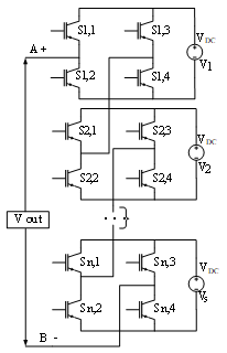
In Cascade H-Bridge Multilevel Inverter (CHB-MLI) topology, the main objective is to synthesize the desired voltage in each H-bridge cell of the power stage from the summation of several levels of DC voltages connected in series to obtain a stepped output voltage waveform [6]. Figure 1 shows the configuration of a single-phase n-levels Cascade H-Bridge Multilevel Inverter.
Figure 1. Configuration of single-phase cascade multilevel inverter
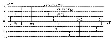
Figure 2. The voltage waveform of a monophasic multilevel 7-level inverter
Multilevel inverters typically are designed using semiconductor power switching devices such as Metal-Oxide-Semiconductor Field-Effect Transistor (MOSFET) or Insulated Gate Bipolar Transistor (IGBT). To obtain a good quality output waveform, a trade-off between two concepts is required: the topology (connection of the switches) and the switching sequence of the switches (on/off). Figure 2 shows the output voltage waveform provided by a single-phase 7-level CHB-MLI.
For this paper, three CHB-MLIs: 5-level, 7-level, and 9-level were simulated using Psim software, employing IGBTs as power semiconductor devices. Each cell is provided with a symmetrical voltage source resulting in the output voltage of 127 Vrms. The modulation index used was 1 (mi=1.0).
In the literature, different modulation techniques have been reported for MLIs in the low switching frequency category to obtain a staggering output voltage waveform [2, 3, 5]. In this category is the so-called Optimized Harmonic Stepped Waveform (OHSW) which can be divided into: Selective Harmonic Elimination (SHE) [7] and Optimal Minimization of the Total Harmonic Distortion (OMTHD) [5, 8]. The following is a brief description of each of them:
3.1 OMTHD method
The OMTHD method is used to minimize the THD value in the output voltage waveform, allowing compliance with IEEE-519 [9]. However, this method does not eliminate low order harmonics.
Minimizing the THD value can be established as an objective function. Eq. (1) expresses the percentage of the THD value of any stepped waveform, with quarter-wave symmetry:
$T H D(\%)=\left[\left(\frac{1}{b_{1}^{2}}\right) \sum_{n=3}^{\infty}\left(b_{n}^{2}\right)\right]^{1 / 2} \cdot 100 \%$ (1)
where,
b1 is the fundamental amplitude.
bnis the amplitude of the n-th harmonic, with n odd.
Because the value of the desired fundamental component cannot be guaranteed, an equality constraint is made, as shown in Eq. (2) because it has a quarter-wave symmetry.
Subject to the following restrictions:
$\theta_{1}<\theta_{2}<\cdots<\cdot \theta_{s}<\pi / 2$ (2)
where,
θ1, θ2, θsare the switching angles in a multilevel inverter.
3.2 SHE method
The main objective of the SHE method is to reduce the content of lower order harmonics, which can be: third, fifth, seventh, ninth, etc. To maintain the value of the fundamental component at the desired value, and achieving the reduction of odd harmonics of low order. To achieve this, a set of transcendental nonlinear equations must be solved simultaneously. The set of equations is as follows:
$\begin{array}{c}
\cos \left(\theta_{1}\right)+\cos \left(\theta_{2}\right)+\cdots+\cos \left(\theta_{s}\right)=k \\
\cos \left(3 \theta_{1}\right)+\cos \left(3 \theta_{2}\right)+\cdots+\cos \left(3 \theta_{s}\right)=0 \\
\cos \left(5 \theta_{1}\right)+\cos \left(5 \theta_{2}\right)+\cdots+\cos \left(5 \theta_{s}\right)=0 \\
\vdots \\
\cos \left(n \theta_{1}\right)+\cos \left(n \theta_{2}\right)+\cdots+\cos \left(n \theta_{s}\right)=0
\end{array}$ (3)
where,
k is the magnitude of the fundamental value proposed.
SHE allows you to select a specific harmonic to eliminate, which will decrease the THD value. The Eq. (3) must be set to zero to eliminate the component of that harmonic, obtaining the appropriate switching angles for semiconductor devices. However, the focus of SHE is the elimination of certain previously selected low order harmonics, instead of minimizing the entire harmonic spectrum [10].
Compared to the SHE method, the OMTHD manipulates the value of the harmonics without maintaining or eliminating any specific harmonics (including the fundamental component) [9].
By setting the calculation of switching angles as an optimization problem, the objective function is to minimize THD, and the decision variables are the switching angles.
The analysis and simulation were carried out with the main objective of comparing the results obtained using NR, GA and PSO to solve the problem of SHE, and to decrease the THD value of the inverter output voltage waveform using OMTHD method.
4.1 Newton Raphson
The Newton-Raphson method presents a reasonably acceptable efficiency in the solution of systems of non-linear equations, converging very quickly and providing a very good precision of the results. This method is very often used for solving problems formulated for teaching in academia and sometimes is directed at solving real-world problems. The main disadvantage of this method is its difficulty in finding a solution for a problem with multiple roots, due to its slow convergence in this type of problems [11, 12]. The NR method requires a good initial guess, without which the solution cannot converge to an optimal value [13].
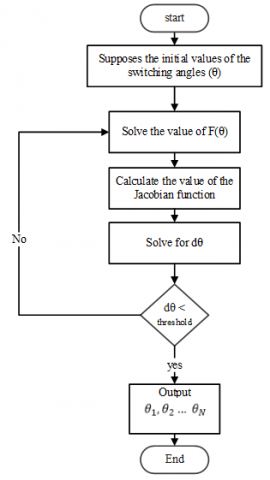
The basic operating principle of the NR algorithm is described below [7]:
$\theta^{m}=\left[\theta_{1}^{m}, \theta_{2}^{m}, \theta_{3}^{m}, \ldots, \theta_{s}^{m}\right]^{T}$ (4)
where,
θmis the angle vector of the initial value assumed.
θm1, θm2, θms are the switching angles.
$F=\left(\theta^{m}\right)=F^{m}$ (5)
where,
F(θm) is the function obtained by Eq. (3).
Fm is the value of the function with the assumed angles.
where,
C is the vector of results obtained by Eq. (3).
$Q^{m}+\left[\frac{\delta f}{\delta m}\right]^{m}+d \theta^{m}=C$ (6)
$d \theta^{m}=\left[d \theta_{1}^{m}, d \theta_{2}^{m}, d \theta_{3}^{m}, \ldots, d \theta_{N}^{m}\right]^{T}$ (7)
Hence
$d \theta^{m}=\left(I N V\left[\frac{\delta f}{\delta m}\right]^{m}\left(C-f^{m}\right)\right)$ (8)
where,
Qm is a vector that linearizes Eq. (3).
$\theta^{m+}=\theta^{m}+d \theta^{m}$ (9)
where,
θm+ is the next value of the switching angles.
dθm is the difference in the values of the angles.
Figure 3 shows the flow chart of the NR algorithm.
Figure 3. Flowchart of the NR algorithm
4.2 Genetic algorithm
In recent decades, there has been a growing interest in algorithms based on the principle of evolution. In the known evolutionary algorithms are included genetic algorithms, based on evolutionary programming and genetic programming. Such a set is called "evolutionary computation" [14].
The evolutionary algorithms used to solve optimization problems are based on search methods to find a set of parameters to minimize or maximize an adaptive function called fitness. These algorithms operate with a population of individuals P(t)= {x1t, …, xnt}, in these each of the individuals is represented by a point of search in the space of solutions to a given problem. The performance of each xi is evaluated following an adaptation function f(xi). such function makes a ranking of the worst of the individuals to the best of the population in a continuous degree of adaptation.
Step1: Randomly generate an initial population, sometimes a heuristic selection can be used. They are regularly based on the principle of survival of the strongest individual.
Step2: Evaluation. To each individual (chromosome) of the population, a survival calculation is made which is represented by Eq. (10)
$P(x)=\frac{f(x)}{\sum f}$ (10)
where,
P(x) is the population
f(x) is the objective function
∑ f = f1+ f2+ … + fNand N is population size.
If the objective function of minimized is given by Eq. (11),
$f(x)=\operatorname{Max}_{f}-f(x)$ (11)
Step3: Stopping criterion:
Selection. Make a choice of individuals to be crossed. These individuals who have better fitness will have a higher probability of being selected.
Crossing. Combination of two chromosomes to generate two descendants resulting in a combination of the characteristics of both chromosomes.
Mutation. Some genes of the daughter chromosomes are randomly modified.
Replacement. Sometimes the new population intersects with the individuals of the previous population and descendants.
4.3 Particle swarm optimization
Particle swarm optimization proposed in 1995 by James Kennedy and Russell C. Eberhart, is described as an optimization technique. Generally, the PSO algorithm is used in search spaces with multiple dimensions [15]. The PSO computational algorithm uses the behavior of insect swarms in nature.
The optimization of the particle swarm algorithm has similarity with the genetic algorithm [16]. The initialization of the PSO algorithm begins with a population of randomly generated solutions. Each potential solution is randomly assigned a velocity vector; the particles are flown through the search space.
Each one of the particles makes use of the tracking in each one of its coordinates in the search space associating it with the best solution achieved until that moment. This value is also known as "pbest". In the same way, a value called "best" in the same way that same value is also tracked. The algorithm as a whole track the general value and location obtained up to that point by any particle in the population, called "gbest".
In summary, the concept of particle swarm optimization is that by each temporal step, making use of the change of velocity (acceleration) of each particle towards the variable pbest and gbest. Acceleration is assigned utilizing a random term, which are generated for the acceleration towards pbest and gbest employing these random numbers [17].
The variables of the objective function are random. Through the iterations, the variable pbest (present best) and gbest (global best) are numbered. The velocity vector V for the variable θ is then numbered using the following expressions:
$\begin{aligned}
V_{(n+1)}=& W V_{n}+C_{1} \operatorname{ran}\left(P_{\text {best}}-X_{n}\right) \\
&+C_{2} \operatorname{ran}\left(G_{\text {best}}-X_{n}\right)
\end{aligned}$ (12)
$X_{(n+1)}=X_{n}+V_{(n+1)}$ (13)
With Eq. (12) it is possible to calculate the velocity of the new particle. This new value depends on the previous speed and the distance of the current position from your best position (individual experience) and the best experience of the swarm (group). In Eq. (13), mention is made of the new position of the particle. Where the constants C1 and C2 are between a range of 1 to 2, the W value (weight of inertia) depends on the type of problem and each criterion. However, choosing a higher W value facilitates the overall scan. On the other hand, choosing a lower value is to adjust the current search area. Choosing an appropriate inertial weight value can achieve a greater skill, as well as quickly finding the overall optimum value.
4.4 Implementation of the methods described
For this paper, symmetric 5-level, 7-level, and 9-level CHB-MLIs were selected. Each one of the H bridges that make up the inverter is an ideal Power Semiconductor Devices (PSDs) made up of IGBTs, the results obtained in the output voltage of the inverter are at f = 50 Hz. As a first step, optimum switching angles are obtained for each case (SHE and OMTHD) employing NR, GA, and PSO. These methods can solve systems of transcendental nonlinear equations using the MATLAB software as a means of obtaining data.
Next, mention is made of the following parameters used for the realization of this work. Table 1 shows the parameters that involve the implementation of the PSO algorithm for the reduction of low order harmonics and the SHE for the multilevel inverter cascade single-phase (5-level, 7- level, and 9-level). It is worth mentioning that the values presented in Table 1, are the default nominal values provided by the software PSO and indicate that they are the appropriate values for a response to a nominal problem, and the selection criterion for considering these values, is that they provide a good solution to the problem posed by the elimination of harmonics in the multilevel inverters.
For the case of GA, the optimization problem was carried out using the MATLAB genetic algorithm toolbox. This algorithm is stopped when the stopping criteria and the restrictions are satisfied. The parameters settings of the Genetic Algorithm used herein are listed in Table 2. It is worth mentioning that the values presented in Table 2, are the default nominal values provided by the software GA and indicate that they are the appropriate values for a response to a nominal problem, and the selection criterion for considering these values, is that they provide a good solution to the problem posed by the elimination of harmonics in the multilevel inverters.
The Psim 9.0.3 software was used for the simulation of the inverters for its subsequent validation. After the implementation of the PSO and GA algorithm, the optimized switching angles were found for the elimination of very low order harmonics, as well as for the reduction to a minimum value of THD.
Table 1. Particle swarm parameters
|
Parameters |
Values |
|
Cognitive constant, C1 |
1.5 |
|
Population size |
200 |
|
Number of decision variables |
2, 3, s |
|
Social constant, C2 |
2.0 |
|
Inertia Weight, W |
1 |
|
Number of iterations |
100 |
Table 2. Genetic algorithm parameters
|
Parameters |
Values |
|
Number of variables |
2, 3, s |
|
Generations |
100 |
|
Population type |
Double vector |
|
Population size |
From 50 to 200 |
|
Creation function |
Constraint dependent |
|
Selection function |
Roulette |
|
Crossover function |
Constraint dependent |
|
Crossover fraction |
0.8 as default |
5.1 OMTHD method results
As a first case study, the OMTHD technique achieves obtaining the optimum switching angles. The objective is to find the minimum value of the THD magnitude, regardless of how much the magnitude of the fundamental component varies, using algorithms of NR, GA, and PSO. Table 3, Table 4, and Table 5 show the results obtained in 5, 7, and 9 levels respectively.
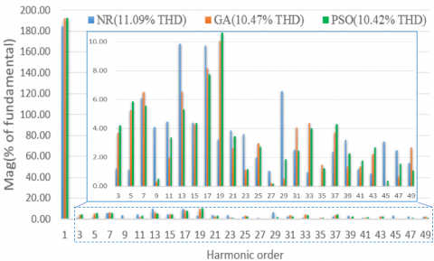
In Figure 4, it is observed employing the Fast Fourier Transform (FFT) analysis corresponding to 7 CHB-MLI that the PSO algorithm in all cases achieves its objective which is the reduction of the THD, likewise obtaining the highest value in its fundamental component.
Figure 5 shows the progress of the iterations performed by the PSO algorithm for a 7-level CHB-MLI, converging to obtain an optimal THD value of 10.43% for the objective function. Observing Figure 5, it can be seen that from iteration 38 the value of the objective function remained constant until the end of the 100 iterations.
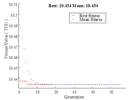
Figure 6 shows the final values for Best and Mean fitness, obtained by the GA for a 7-level CHB-MLI. Figure 6 shows that Best fitness is always less (or equal) to Mean fitness, and the difference between both continues decreasing over time (until the algorithm converges completely, and the population will contain N copies of the same "best" individual). In this case, convergence occurs at generation 18.
Table 3. Comparison of NR, GA and PSO Algorithm for CHB-MLI 5 level using OMTHD
|
Angle |
NR |
GA |
PSO |
|
θ1 |
11.80 |
14.33 |
13.40 |
|
θ 2 |
41.77 |
42.10 |
41.91 |
|
%THD |
15.51 |
15.35 |
15.29 |
Table 4. Comparison of NR, GA and PSO Algorithm for CHB-MLI 7 level using OMTHD
|
Angle |
NR |
GA |
PSO |
|
θ1 |
8 |
8.08 |
8.69 |
|
θ2 |
30 |
28.35 |
27.89 |
|
θ3 |
56 |
50.18 |
49.81 |
|
%THD |
11.09 |
10.47 |
10.42 |
Table 5. Comparison of NR, GA and PSO Algorithm for CHB-MLI 9 level using OMTHD
|
Angle |
NR |
GA |
PSO |
|
θ1 |
10 |
9 |
6.86 |
|
θ2 |
21.73 |
21.21 |
20.78 |
|
θ3 |
40 |
35.84 |
35.51 |
|
θ4 |
60 |
56.06 |
55.80 |
|
%THD |
8.65 |
7.92 |
7.63 |
Table 6 shows the value of the voltage output quantity (fundamental component) expressed in volts.
Table 6. Fundamental voltage amplitude value (m). Using OMTHD
|
CHB-MLI |
NR |
GA |
PSO |
|
5-level |
197.9V |
196.4V |
197.1V |
|
7-level |
184.9V |
192.1V |
192.7V |
|
9-level |
182.6V |
188.8V |
189.6V |
Figure 4. FFT analysis corresponding to 7 CHB-MLI, using OMTHD method
Figure 5. Execution curve objective function vs the number of iterations in the PSO algorithm
Figure 6. Fitness value execution curve vs the number of generations in the GA algorithm
5.2 SHE method results
The second case of study the obtaining of the optimum commutation angles for the SHE technique utilizing NR, GA, and PSO, Tables 7, 8, 9 shows the results obtained in 5, 7, and 9 levels respectively. The obtained results show that in two solutions the optimization by GA manages to obtain a minimum value of minimization of THD, nevertheless, the algorithm of PSO achieves the commitment with the elimination of the harmonics of lower order.
Table 7. Comparison of NR, GA and PSO Algorithm for CHB-MLI 5 levels using SHE
|
Angle |
NR |
GA |
PSO |
|
θ1 |
12.30 |
11.95 |
12.30 |
|
θ2 |
49.20 |
48.03 |
48.02 |
|
%THD |
16.93 |
16.43 |
16.25 |
Table 8. Comparison of NR, GA and PSO Algorithm for CHB-MLI 7 levels using SHE
|
Angle |
NR |
GA |
PSO |
|
θ1 |
13.06 |
12 |
11.70 |
|
θ2 |
26 |
26.93 |
26.87 |
|
θ3 |
57 |
55.49 |
56.06 |
|
%THD |
12.49 |
11.57 |
11.43 |
Table 9. Comparison of NR, GA and PSO Algorithm for CHB-MLI 9 levels using SHE
|
Angle |
NR |
GA |
PSO |
|
θ1 |
3 |
2 |
2.03 |
|
θ2 |
30 |
24 |
24.92 |
|
θ3 |
33 |
36.51 |
35.23 |
|
θ4 |
162 |
60 |
60.84 |
|
%THD |
12.91 |
9.78 |
10.28 |
An important parameter is in the same way very important in the multilevel inverters as it is the magnitude of the output voltage (fundamental component). This value refers to the amount of energy supplied by the inverter to the load. Table 10 shows the magnitude of the output voltage obtained from the simulation.
Table 10. Fundamental voltage amplitude value (m). Using SHE
|
CHB-MLI |
NR |
GA |
PSO |
|
5-level |
185.7V |
190.4V |
189.3V |
|
7-level |
185.0V |
186.5V |
186.0V |
|
9-level |
182.1 |
184.6 |
184.3V |
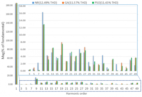
An example of this is shown in Figure 7, where the FFT corresponding to 7 CHB-MLI is displayed, eliminating the 3rd, 5th, and 7th harmonic order.
Figure 7. FFT analysis corresponding to 7 CHB-MLI, eliminating 3rd, 5th, and 7th harmonics order
For all cases, the NR algorithm has not been able to converge to an optimal solution and this is because it is not able to distinguish between an optimal global and local value, being trapped in these latter values.
Usually making use of the multilevel topology by increasing the number of levels, a much lower THD value is obtained, since the values of the commutation angles can be improved, this problem is taken as an optimization case.
For this paper, a single-phase Cascade H-Bridge Multilevel Inverters (CHB-MLI or CMLI) topology with independent DC sources, was selected as a case study. An analysis was carried out considering three scenarios: 5-level, 7-level, and 9-level applying the concept of the Optimized Harmonic Stepped-Waveform (OHSW) and comparing the results between the Optimal Minimization of the Total Harmonic Distortion (OMTHD) and the Selective Harmonic Eliminated PWM (SHE-PWM). MATLAB software was used to solve the systems of transcendental nonlinear equations to obtain the optimal angles by applying the NR, GA, and PSO methods. Subsequently, the simulation of each case was performed under analysis in the Psim software to compare the THD values obtained.
Using the OMTHD technique, the best THD value reduction results were obtained with the PSO algorithm. In contrast, using the classical NR optimization method, it presented higher THD values for all cases.
Finally, analyzing the results obtained with the SHE method eliminating the low order harmonics according to the case, a greater reduction of the THD value was achieved in most of the analyzed cases, using the PSO algorithm.
[1] Babaei, E., Hosseini, S.H. (2009). New cascaded multilevel inverter topology with minimum number of switches. Energy Conversion and Management, 50: 2761-2767. https://doi.org/10.1016/j.enconman.2009.06.032
[2] Ozpineci, B., Tolbert, L.M., Chiasson, J.N. (2004). Harmonic optimization of multilevel converters using genetic algorithms. 2004 IEEE 35th Annual Power Electronics Specialists Conference Aachen, Germany, pp. 3911-3916. https://doi.org/10.1109/PESC.2004.1355167
[3] Neralwar, K.S., Meshram, P., Borghate, V. (2016). Genetic algorithm (GA) based SHE technique applied to seven-level Nested Neutral Point Clamped (NNPC) Converter. 2016 IEEE 1st International Conference on Power Electronics, Intelligent Control and Energy Systems (ICPEICES), Delhi, pp. 1-6. https://doi.org/10.1109/ICPEICES.2016.7853430
[4] De León-Aldaco, S.E., Calleja, H., Alquicira, J.A. (2015). Metaheuristic optimization methods applied to power converters: A review. IEEE Transactions on Power Electronics, 30: 6791-6803. https://doi.org/10.1109/TPEL.2015.2397311
[5] Aguayo-Alquicira, J., León-Aldaco, S.E.D., Calleja-Gjumlich, J.H., Claudio-Sánchez, A. (2020). Switching angles calculation in multilevel inverters using triangular number sequence – A THD minimization approach. European Journal of Electrical Engineering, 22(1): 49-55. https://doi.org/10.18280/ejee.220106
[6] Prakash, G., Subramani, C., Bharatiraja, C., Shabin, M. (2016). A low cost single phase grid connected reduced switch PV inverter based on Time Frame Switching Scheme. International Journal of Electrical Power & Energy Systems, 77: 100-111. https://doi.org/10.1016/j.ijepes.2015.11.028
[7] Mistry, T., Bhatta, S.K., Senapati, A.K., Agarwal, A. (2015). Performance improvement of induction motor by Selective Harmonic Elimination (SHE) using Newton Raphson (NR) method. 2015 International Conference on Energy Systems and Applications, Pune, pp. 364-369. https://doi.org/10.1109/ICESA.2015.7503372
[8] Yousefpoor, N., Farokhnia, N., Fathi, S., Moghani, J. (2009). Developed single-phase OMTHD technique for cascaded multi-level inverter by considering adjustable DC sources. 2009 International Conference on Electric Power and Energy Conversion Systems, (EPECS), Sharjah, pp. 1-6. https://ieeexplore.ieee.org/document/5415688
[9] Duffey, C.K., Stratford, R.P. (1989). Update of harmonic standard IEEE-519: IEEE recommended practices and requirements for harmonic control in electric power systems. IEEE Transactions on Industry Applications, 25: 1025-1034. https://doi.org/10.1109/28.44238
[10] Awais, M., Ilyas, H., Younus, H.B., Raza, M.A., Abbas, T. (2016). Optimal switching angles for minimization of total harmonic distortion in single phase cascaded multilevel inverters. 2016 19th International Multi-Topic Conference (INMIC), Islamabad, pp. 1-6. https://doi.org/10.1109/INMIC.2016.7840150
[11] Sarnari, A.J., Živanović, R. (2017). Reliable steady state voltage stability limit estimation using Newton-Raphson-based method. 2017 Australasian Universities Power Engineering Conference (AUPEC), Melbourne, VIC, pp. 1-6. https://doi.org/10.1109/AUPEC.2017.8282450
[12] Gupta, V.K., Mahanty, R. (2015). Optimized switching scheme of cascaded H-bridge multilevel inverter using PSO. International Journal of Electrical Power & Energy Systems, 64: 699-707. https://doi.org/10.1016/j.ijepes.2014.07.072
[13] Mahesh, A., Sandhu, K.S. (2018). Evolutionary algorithm based optimal angle strategy for a cascade h-bridge inverter. Procedia Computer Science, 125: 412-419. https://doi.org/10.1016/j.procs.2017.12.054
[14] Koza, J.R. (1992). Genetic programming II, automatic discovery of reusable subprograms. MIT Press, Cambridge, MA, Section II, pp 17-66. https://mitpress.mit.edu/books/genetic-programming-ii
[15] Kennedy, R., Eberhart, J. (1991). Particle swarm optimization. Proceedings of ICNN'95 - International Conference on Neural Networks, Perth, WA, Australia. pp. 1-5. https://doi.org/10.1109/ICNN.1995.488968
[16] Davis, L. (1991). Handbook of genetic algorithms, Van Nostrand Reinhold; Edición: 1st. Van Nostrand Reinhold, New York. http://papers.cumincad.org/cgi-bin/works/paper/eaca.
[17] Eberhart, R., Kennedy, J. (1995). A new optimizer using particle swarm theory. MHS'95. Proceedings of the Sixth International Symposium on Micro Machine and Human Science, Nagoya, Japan, pp. 39-43. https://doi.org/10.1109/MHS.1995.494215