Preeti Gupta* | Pankaj Swarnkar
© 2020 IIETA. This article is published by IIETA and is licensed under the CC BY 4.0 license (http://creativecommons.org/licenses/by/4.0/).
OPEN ACCESS
Intertied hybrid power system comprises of multi-frequency, multi-voltage individual hybrid power system (HPS). The benefit of intertied HPS includes reduced reserve capacity, improved voltage & frequency regulation, and flexibility in operating voltage & frequency. These benefits can be attained by a suitably designed power management scheme. There are many methods available to manage the power in stand-alone intertied HPS, out of them conventional droop control is simple and popular method, although it has limitations in terms of overlooking system capacity and deviation of voltage & frequency with sudden impact of loads. This necessitates an adaptive power sharing method which should cope with the coordinated deviation in voltage and frequency. Therefore coordinated droop control for multi-frequency, multi-voltage intertied HPS is proposed in this work. In proposed control scheme a correction factor with respect to system capacity and critical load capacity is integrated to achieve coordinated deviation in voltage and frequency which conquer the limitations of conventional method.
intertied hybrid power system, droop control, interlinking power converter, coordinated control, adaptive power sharing
Hybrid power system (HPS) comprises of various energy sources (conventional & renewable) like PV, fuel cells, wind generators, diesel generators and various storage technologies like batteries, flywheels and ultra-capacitors [1]. Hybrid power system is better means of utilization of renewable energy and diminishing the environmental hazard of fossil fuels. A few applications of hybrid power systems are observed in the industrial, institutional, navy, marine, aerospace, and remote area etc. There are many research possibilities in hybrid power systems with intention to strengthen the system capacity and enhancement in the efficiency and reliability. As majority of utility grids are still operating on AC system, AC HPS are more popular however renewable sources with DC output emerged the concept of DC HPS. A hybrid power system has benefits of optimum use of available resources, improved stability, reliability, though the hybrid power system has limitations to supply either AC or DC load depending on the source. These limitations are overcome by intertied hybrid power system which is formed by interlinking of different types of hybrid power systems compatible with both AC and DC technologies. AC and DC HPS can be operated independently, but for more reliability and security they are intertied by interlinking power converters. Intertied HPS by interlinking power converters for AC-DC HPS has been successfully investigated [2-6]. These intertied HPS can support self-sustaining military base, hospitals, industrial plants, or institutions where power outage is not permissible. The intertied HPS may also be designed with own preferred frequency, voltage and network arrangement to meet the load demand. It is essential to manage the power in the intertied HPS through a controller for better power sharing, stable operation and high efficiency [7]. The intertied HPS is a focus of research due to its high reliability and flexibility with integration of renewable energy sources.
Research on intertied HPS has grown progressively but mainly confined to single frequency and single voltage AC-DC HPS [8]. Consequently, interlinking of multiple frequency AC HPS and multiple voltage DC HPS merges the profits of each HPS. An intertied hybrid power system can better share active and reactive powers among its entities by selecting different frequencies and voltages in individual HPS for improved performance and supply reliability. Intertied HPS are working as autonomous system with their own preferred voltage and frequencies. A physical dual frequency system of 50 Hz and 60 Hz interlinked by interlinking power converter has been built for Ross Island Antarctica Project (Dual frequency) [9]. These systems have the advantages of enhanced reliability, security and efficiency with optimal use of energy resources. This dragged the attention of researchers in the area of intertied HPS in last few years.
Also, research shows that the multi-frequency AC HPS and multi-voltage DC HPS comprising of different AC-DC HPS operating at their rated voltages and frequencies will be able to reduce transmission and distribution losses, which create interest of researchers in intertied HPS. Having different voltage and frequency introduces more flexibility into the system, and inter-tying with other HPS requires the insertion of interlinking power converters. Control of standalone hybrid power system is complex but has wide applications in remote areas [10-12]. The main control variables of an intertied hybrid power system are voltage, frequency, active and reactive power. The design of power sharing controller is a major challenge due to the variation in operating frequency and voltage of AC & DC HPS. Since the considered system is in stand-alone mode the control strategy is complex and should maintain the common DC bus voltage with adaptive power sharing and limited deviation in AC HPS frequency and DC HPS voltage under varying load conditions. There are many control techniques for intertied HPS has been already proposed in literature. In centralized control, the need for fast communication link and single point failure decreases the reliability which realized the need of decentralized controllers for power sharing where droop control methods are more popular. Various droop control methods have been proposed in the literature for AC and DC HPS which offers simplicity and better performance. Various droop control methods like conventional droop [13-16], voltage-real power droop (VPD) [17], frequency-reactive power boost droop (FQB) [17, 18], Q-V droop [19], angle droop [19], virtual frame transformation [20], virtual impedance method [21], integral droop [22], adaptive droop [23] etc. are already in existence. Conventional droop control is a popular method to manage the power in stand-alone mode of intertied HPS due to its simplicity. However limitations of conventional droop in terms of influenced by system parameters, poor voltage regulation, bandwidth variation of active and reactive power controllers affects the voltage and frequency control motivated to work in the area of specific droop control for intertied HPS. Intertied hybrid power systems with same or different voltage or frequency has the advantages like fulfillment of power demand, enhanced reliability, security and efficiency with optimum use of resources [24, 25]. Controlling of multiple voltages and multiple frequencies in intertied HPS is challenging task [26]. Power quality issues with multiple power electronic interfaces in intertied HPS are another major concern [27, 28]. Another challenge with intertied hybrid power system is appropriate power sharing with coordinated deviation in voltage and frequency for sudden load change in consideration to system capacity has to be addressed by autonomous control without communication link [29-32]. In this context proper controller with power management strategy is required which should cope with the deviation with voltage and frequency in comparison to existing control [33-37].
In perspective of the literature survey following research gaps have been identified.
(1) Autonomous control for multi-frequency and multi-voltage intertied HPS is missing.
(2) Improved power sharing within the intertied HPS with coordinated deviation in voltage & frequency and flexibility in selection of voltage & frequency for HPS along with consideration of system capacity is missing.
(3) Multi-frequency control and multi-voltage control should incorporate corrections obtained from coordinated control to consider system capacity.
To overcome above mentioned issues control power sharing in multi-frequency and multi-voltage intertied HPS normal droop techniques cannot be feasible. So there is requirement of specific droop technique which assures better voltage regulation and accurate power sharing among sources. This task can be fulfilled only when the control technique considers the system capacity and critical load so that accurate power sharing is assured among each HPS and loads [33-37].
Following contributions have been presented by author in this paper.
(1) Coordinated multi-voltage, multi-frequency droop control is a better choice in which by including correction factor in terms of system capacity and critical load, better performance of the system can be achieved.
(2) To get the correction factor including system capacity, coordinated control among individual HPS is preferred which ensures power fluctuations to be divided in all HPSs.
(3) Proposed power sharing controller for intertied HPS should be capable of handling the power management, coordinated deviation in voltage & frequency and flexibility in selection of voltage & frequency for HPS along with consideration of system capacity.
The structure of this paper is organized as follows: Section-2 presents coordinated control, Section-3 presents adaptive multi-frequency control and Section-4 discuses adaptive multi-voltage control, performance evaluation of proposed control strategy is analyzed in Section-5 and Section-6 presents conclusion.
In perspective of the control structure, power interaction among different HPS in a stand-alone intertied system is more complicated. Since power fluctuations result in the change in the output of system; coordinated control among individual HPS ensures power sharing among different HPS. Since in all HPS, droop controlled strategy is preferred; thereby AC frequency and DC voltage vary according to change in load demand. Here both AC and DC HPS are connected to common bus. To maintain the proper power sharing among different HPS necessitates coordinated control strategy. The objective of coordinated combined AC-DC droop based adaptive controller is to share appropriate active power in intertied HPS with coordinated voltage and frequency deviation under varying load conditions. The proposed control technique is designed with adaptive correction factors δv and δf for combined AC-DC droop. The control law for adaptive correction factors for p no. of AC HPS and q no. of DC HPS can be expressed as
$\delta f_{p}=\left(k_{p, p}+\frac{k_{i, p}}{s}\right)\left[\frac{\left(v_{c b}-v_{c b}^{*}\right)}{v_{c b}^{\max }-v_{c b}^{\min }}-\alpha_{p} \frac{f_{p}-f_{p}^{*}}{f_{p}^{\max }-f_{p}^{\min }}\right]$ (1)
$\delta v_{q}=\left(k_{p, q}+\frac{k_{i, q}}{s}\right)\left[\frac{\left(v_{c b}-v_{c b}^{*}\right)}{v_{c b}^{\max }-v_{c b}^{\min }}-\alpha_{q} \frac{v_{d c, q}-v_{d c ., q}^{*}}{v_{d ., q}^{\max }-v_{d c, q}^{\min }}\right]$ (2)
Here δfp and δvq are the coordinated control signal for IPC of pthAC HPS and qth DC HPS respectively. AC and DC HPS, PI parameters are kp and ki. αp and αq are the correction coefficients in consideration to capacity of pth AC and qth DC HPS respectively. Here f and vcb denotes frequency and common bus voltage with superscript *, max, min are used for rated values, maximum and minimum values respectively. By considering the capacity of the system, it is easier to support weak HPS by strong HPS. The proposed correction coefficient of pth HPS is represented as
$\alpha_{p}=\left(\frac{H_{p}^{\text {total}}}{H^{\text {total}}}\right)^{-1} \frac{H_{p}^{c}}{H_{p}^{\text {total}}}$ (3)
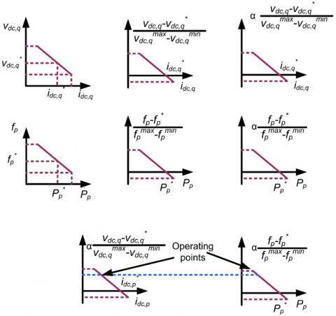
Figure 1. Corrections for coordinated power control
where, Hptotal and Hpc are total and critical load capacity of pth HPS and Htotal is the total capacity of intertied HPS. The value αp is large for small capacity of HPS with high amount of critical load connected, resulting in small deviation in DC voltage and AC frequency. Also, synchronization with change in voltage and frequency proves the efficacy of the proposed control technique. In coordinated operation ac frequencies and dc voltages decrease or increase at the same time. This results in synchronized changes in AC and DC HPS power. Under steady state condition, the relation between voltage and frequency considering capacity of the system is given by
$\frac{v_{c b}-v_{c b}^{*}}{v_{c b}^{\max }-v_{c b}^{\min }}=\alpha_{p} \frac{f_{p}-f_{p}^{*}}{f_{p}^{\max }-f_{p}^{\min }}=\alpha_{q} \frac{v_{d c, q}-v_{d c, q}^{*}}{v_{d c, q}^{\max }-v_{d c, q}^{\min }}$ (4)
Figure 1 shows the corrected relative changes in AC frequency and DC voltage for proposed control algorithm. The operating points on AC and DC droop are the basis of active power sharing. The feedback variables positioned at IPCs to share the coordinated power can be realized to improve the reliability of the system.
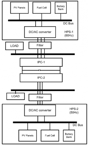
This method is proposed to connect two AC HPS of frequency 50Hz and 60Hz. The multi-frequency system is shown in Figure 2, where an interlinking power converter is responsible for bidirectional power flow between two HPS of different frequency. As the intertied HPS considered is in stand-alone mode so the increase/decrease in demand causes deviation in frequency. This frequency deviation needs attention as it may causes failure of devices. So in order to protect the whole system controllers have to be designed in such a way that it should not cause more deviation in frequency with sudden impact of increase/decrease in load.
Figure 2. Multi frequency system configuration
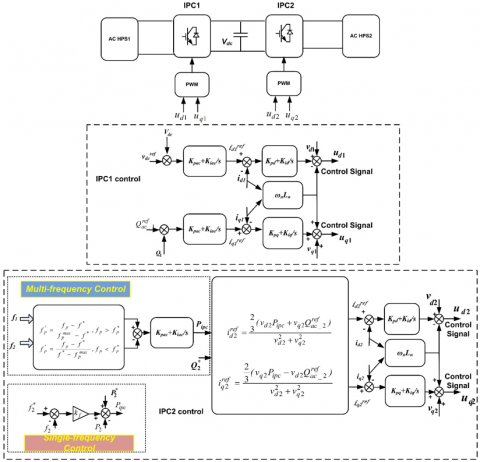
Figure 3. Control circuit for single and multi-frequency control
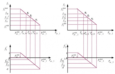
Figure 4. Multi-frequency droop and normalized frequency characteristics of HPS1, and HPS2
IPC1 regulates DC link voltage while IPC2 regulates the frequency of HPS1 and HPS2. The outputs of current control loop ud1 and uq1 can be represented as:
$u_{d 1}=v_{d 1}-i_{q 1} \omega_{1} L_{1}+k_{p}\left(i_{d 1}^{r e f}-i_{d 1}\right)+k_{i} \int\left(i_{d 1}^{r e f}-i_{d 1}\right) d t$ (5)
$u_{q 1}=v_{q 1}-i_{d 1} \omega_{1} L_{1}+k_{p}\left(i_{q 1}^{r e f}-i_{q 1}\right)+k_{i} \int\left(i_{q_{1}}^{r e f}-i_{q 1}\right) d t$ (6)
where, id1ref and id1 are the reference and measured currents of HPS1, respectively; $\omega_{1}$ is the angular frequency of HPS1, kp and kiare the proportional-integral (PI) parameters of current control loop. The DC link voltage controller generates reference current id1ref as:
$i_{d 1}^{r e f}=k_{p d}\left(v_{d c}^{r e f}-v_{d c}\right)+k_{i d} \int\left(v_{d c}^{r e f}-v_{d c}\right) d t$ (7)
$i_{q 1}^{r e f}=k_{p q}\left(Q_{a c-1}^{r e f}-Q_{1}\right)+k_{i q} \int\left(Q_{a c-1}^{r e f}-Q_{1}\right) d t$ (8)
where, vrefdc and vdc are the reference and measured dc-voltages of the interlinking power converter, respectively; kpq, kiq and kpd, kid are the PI parameters of the voltage controller and DC-link voltage controller respectively, Qrefac_1and Q1 are reference and measured reactive power. IPC2 has responsibility of multi-frequency control which comprises of reactive power control loop, current control loop, and multi-frequency control loop. Here irefd2 and irefq2 are the reference direct axis and quadrature axis current of HPS2. The generation of reference currents, irefd2 and irefq2, is through reference real and reactive power.
$i_{q 1}^{r e f}=\frac{\frac{2}{3}\left(v_{d 2} P_{I P C}+v_{q 2} Q_{a c-2}^{r e f}\right)}{v_{d 2}^{2}+v_{q 2}^{2}}$ (9)
$i_{q 2}^{r e f}=\frac{\frac{2}{3}\left(v_{q 2} P_{I P C}-v_{d 2} Q_{a c-2}^{r e f}\right)}{v_{d 2}^{2}+v_{q 2}^{2}}$ (10)
The reference real power PIPC is given by
$P_{I P C}=k_{p a c}\left(f_{1}^{\prime}-f_{2}^{\prime}\right)+k_{i a c} \int\left(f_{1}^{\prime}-f_{2}^{\prime}\right) d t$ (11)
The control strategy for multi-frequency control is shown in Figure 3.
Power sharing among sources in an AC HPS can be accomplished through droop control method with δf as the change in the frequency obtained from Eq. (1) with change in load among different HPS obtained from coordinated control among different AC HPS. Here Pac-p is the power output and Pac-pmax is the maximum active power. Power sharing among p sources in AC HPS can be obtained as
$\frac{P_{a c-1}}{P_{a c-1}^{\max }}=\frac{P_{a c-2}}{P_{a c-2}^{\max }} \ldots \ldots \frac{P_{a c-p}}{P_{a c-p}^{\max }}$ (12)
The objective of coordinated droop based adaptive controller is to share appropriate active power in intertied HPS with coordinated frequency deviation under varying load conditions. Here f’1 and f’2 represent normalized frequencies of individual AC HPS1 and AC HPS2 respectively. PIPC represents power flow through interlinking power converter. Here Kpac and Kiac are the proportional and integral control gain for the multi frequency control. Qrefac_2 represents reference reactive power of the HPS2. The normalization of individual HPS frequency is done to achieve limited frequency deviation. Figure 4 shows the proposed droop control for AC HPS. Initially, the normal operation points of two HPS are represented as X1and X2. The sudden increase in load on HPS1 reduces HPS1 frequency from f10 to f11. The operating point of HPS1 shifts from X1 to Y1. To compensate the load disturbance in HPS1, power from HPS2 is transferred to HPS1 through IPC. In order to accomplishment of this task, the adaptive controller senses the difference in the reference and the measured values of load power and generates the correction factor accordingly. This control action results in recovery of HPS1 frequency although HPS2 frequency decreases slightly. By proposed control, the frequencies of HPS1 and HPS2 are achieving new steady-state values (Z1 and Z2). Where, f1represents the measured frequency of HPS1, f* is the rated frequency of HPS1, f’1 is the normalized frequency of HPS1.
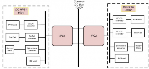
The It is a challenging situation for flexible intertied HPS in stand-alone operation where the total load is to be shared and managed autonomously. The proposed scheme involves fast and flexible power control which minimizes the system dynamics. The adaptive control proposed includes coordinated control to share appropriate power among different HPS according to their ratings. The proposed control technique is designed with adaptive correction factors δv obtained from Eq. (2) for intertied HPS. Since power fluctuations result in change in the output of system; coordinated control among individual HPS ensures power sharing among different HPS. The objective of proposed controller is to share appropriate active power in intertied HPS with coordinated voltage deviation under varying load conditions. The proposed control technique is designed with adaptive correction factors δv. This method is proposed to connect q no. of DC HPS with common bus. For simplicity in this case two DC HPS of voltages 500V and 800V through a common DC bus of 1000V is considered as shown in Figure 5, where interlinking power converter (IPC) is responsible for bidirectional power flow between two HPS of different voltages.
DC sources are connected to DC bus through bidirectional converter. The function of IPC1 is to maintain the common bus voltage with bidirectional power flow. Bidirectional converter can be isolated or non-isolated. In non-isolated converter source and load does not have galvanic isolation while in isolated converter there is galvanic isolation by high frequency transformer. Due to simplicity of non-isolated converter it has been used in this work. The control strategy adopts droop control for power sharing among DC HPS. The control method for multi-voltage control is shown in Figure 6.
Figure 5. Multi-voltage control system configuration
Figure 6. Control circuit for multi-voltage control
Power sharing through DC-HPS droop control is simple where DC sources are controlled with one droop characteristic given by
$v_{d c}^{r e f}=\left(v_{d c}^{*}+\delta v_{q}\right)-r_{q} i_{d c}$ (13)
Here the variables used as vdcref, vdc*, rq, idc, δvq are reference output DC voltage, rated DC voltage, droop coefficient, actual output DC current, and coordinated control signal for IPC of qth DC HPS. For different DC HPS vdc* can be different. Droop coefficient rq and correction factor δvqis given by
$r_{q}=\frac{V_{d c}^{\min }-V_{d c}^{\max }}{P_{d c-q}^{\max }}$ (14)
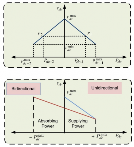
Figure 7 shows the droop characteristics of power sharing in multi-voltage DC HPS with droop coefficient as rq (i.e. r1 and r2). Here the droop characteristics shown clearly mention the bidirectional power sharing of IPC in both modes (unidirectional and bidirectional).
Figure 7. Droop characteristics of multi-voltage control of DC HPS
To analyze the performance of multi-frequency and multi-voltage intertied HPS two methods: conventional droop and adaptive coordinated droop have been proposed. Adaptive coordinated droop technique is designed with system capacity into consideration and then correction factor is employed to achieve better power sharing with reduced deviation in frequency and voltage. Proposed adaptive coordinated droop considers the load and system capacity and automatically calculates correction factor under varying load condition and makes the system adaptive. A comparative conventional droop control and adaptive coordinated droop control for multi-frequency and multi-voltage intertied HPS has been done. By analyzing the performance of the control schemes it has been observed that adaptive coordinated droop provides better power sharing and less deviation in frequency and voltage as compared to existing techniques. MATLAB/simulink environment has been used to prove the efficacy of proposed methods. Proposed control methods have been assessed on the basis of deviation in voltage and frequency. In adaptive coordinated droop control correction factor automatically changes with loading and integrated which makes the system adaptive and results in less deviation in voltage and frequency.
5.1 Performance evaluation of intertied HPS for multi-frequency control
Frequency plays an important role in the system stability. If the frequency deviates from desired value there will be frequency-power imbalance and may result in power system collapse. Frequency deviation under the prescribed limit is necessary requirement for proper working of the system. The main aim of the proposed control is to get the deviation in frequency under the prescribed limit under load changing scenario. The test system comprises of two stand-alone HPS; HPS1 and HPS2 of frequency 60Hz and 50Hz respectively. The maximum frequency deviation of 1% is permissible. Various load change scenarios are considered in this case. HPS1 and HPS2 rated powers are taken as 80KW and 120KW respectively. The proposed controller dynamic performance is compared with the single frequency control method. In single frequency control, if one HPS is overloaded the frequency deviation will be observed in that HPS only while other HPS will have the constant frequency. This shows that the additional load applied to one HPS is not shared by the other. In multi-frequency control, if one HPS is overloaded the other HPS is forced to share the load so that the deviation in frequency should be less. To verify the effectiveness of multi-frequency control low overloading and heavy overloading conditions are analyzed. This can be observed by frequency deviation in both HPS at much reduced level. Two cases considered in this study are as follows:
5.1.1 Case-I: Low overloading on HPS2
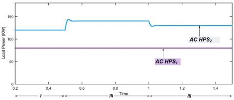
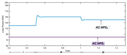
Figure 8 shows variation of load power with time where state-I represent rated state with HPS2 loading 120KW, in state-II load power of HPS2 changes from 120KW to 140KW and in state-III load of HPS2 decreases from 140KW to 130KW while HPS1 is delivering 80KW in all states. In state-II and state-III overloading of 16.7% and 8.3% occurred respectively. Initially system is working at normal frequency under rated load condition. In state-II and state-III when 20KW and 10KW additional load is connected respectively at HPS2 causes reduction of the frequency in HPS2 only by single frequency control while in multi-frequency control deviation in frequency of HPS1 and HPS2 are shared according to system capacity.
Figure 8. Load power under case-I for single-frequency and multi-frequency control
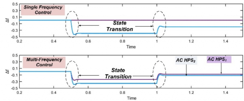
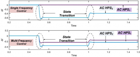
Figure 9. Deviation in frequency of HPS1 and HPS2 under case-I for single-frequency and multi-frequency control
Figure 10. Load power under case-II for single-frequency and multi-frequency control
Figure 11. Frequency of HPS1 and HPS2 under case-II for single-frequency control and multi-frequency control
As observed from Figure 9, in state-II single frequency controller results in deviation of frequency for HPS2 by about 0.4 Hz while in multi-frequency controller the deviation observed in HPS1 by 0.16 Hz and HPS2 by 0.24 Hz which is very small in comparison to single frequency controller. In state-III single frequency controller results in deviation of frequency in HPS2 by 0.2 Hz while in multi-frequency controller, deviation in frequency is observed as 0.08 Hz and 0.12 Hz respectively for HPS1 and HPS2. The deviation in frequency in both the control is under the limit for low overloading condition however less deviation is observed in multi-frequency control as compared to single frequency control.
Results of single frequency control shown in Figure 9 indicate that overloading of 20KW and 10KW on HPS2 in state-II and state-III respectively are not shared by HPS1. That is why there is large frequency variation in HPS2 while there is no frequency variation in HPS1. With the application of multi-frequency control, the overloading of HPS2 is shared by HPS1 causing a slight frequency variation in HPS1 (less than 1%) which is negligible. Also with the application of multi-frequency control the frequency deviation in HPS2 is also reduced as compared to deviation in single frequency control. Here total overloading on HPS2 is 16.7% and 8.3% which is shared by HPS1 and HPS2 with 40% and 60% so that there will be lesser burden on both of the HPS and less frequency deviations are observed in both HPS. This makes the system more reliable especially in case of variation in load. It is clear that system response for load varying condition is improved with multi-frequency controller as compared to single frequency controller.
5.1.2 Case-II: Heavy overloading on HPS2
This case represents heavy overloading on HPS2 which causes system frequency to cross the threshold limit. In this case state-I is rated state with HPS2 rated loading 120KW, in state-II at 0.5sec 30KW additional load is connected on HPS2 and in state-III at 1 sec 20KW additional load is connected at on HPS2. HPS1 load is 80KW for all states. In state-II and state-III overloading of 25% and 16.7% occurred respectively. Figure 10 represents variation of load power with time in case-II.
As HPS2 is heavily overloaded the frequency of HPS2 drops suddenly by 0.6Hz and 0.4Hz in state-II and state-III respectively for single frequency controller which crosses threshold limit. To overcome the problem of over limit of frequency deviation in single frequency control load is shared in multi-frequency controller so that the frequency deviations in state-II for HPS1 and HPS2 are 0.24Hz and 0.36Hz respectively while in state-III frequency deviations for HPS1 and HPS2 are 0.16Hz and 0.24Hz respectively. Frequencies of the two HPS are regulated within the allowable deviation range for multi-frequency control. The frequency deviations of both HPS with the disturbance of load in HPS2 for single and multi-frequency control are shown in Figure 11.
Results of single frequency control shown in Figure 11 indicate that overloading of 30KW and 20KW on HPS2 in state-II and state-III respectively are not shared by HPS1 which results in large frequency variation of 0.6Hz in HPS2 (more than prescribed limit i.e. +0.5 Hz) while there is no frequency variation in HPS1. With the application of multi-frequency control the overloading of HPS2 is shared by HPS1 causing a slight frequency variation in HPS1 (less than 1%) which is negligible. Also with the application of multi-frequency control the frequency deviation in HPS2 is also reduced as compared to deviation in single frequency control. Here total overloading is shared by HPS1 and HPS2 with 40% and 60% respectively so that there is not over burden on any of the HPS and less frequency deviations are observed in both HPS. This improves the system reliability particularly in case of variation in load and defines the suitability of method for multi-frequency intertied HPS. The multi-frequency control proposed for managing the frequencies of multi-frequency intertied HPS is effective for power sharing among two HPS. A comparison study for frequency deviation with single frequency control and multiple frequency control for both cases has been presented in Table 1.
Table 2 shows the %overloading shared by both HPS under single frequency control and multi-frequency control. It is clear from Table 1 and Table 2 that in case-II for t=0.5 sec. with single frequency control, frequency deviation is beyond threshold limit while multi-frequency control results in less deviation by sharing overload on HPS1 and HPS2. The multi-frequency control strategy is suitable for intertied HPS due to the ability of bidirectional power sharing among two HPS. It is a simple approach which provides better power sharing without any communication link so offers reduced cost with no single point failure.
Table 1. Deviation of frequency in Hz for single and multi-frequency control
|
Case |
Time (sec.) |
Single Frequency Control |
Multi-frequency Control |
||
|
HPS1 |
HPS2 |
HPS1 |
HPS2 |
||
|
Case-I |
t=0.5 |
0 |
0.4 |
0.16 |
0.24 |
|
t =1 |
0 |
0.2 |
0.08 |
0.12 |
|
|
Case-II |
t =0.5 |
0 |
0.6 |
0.24 |
0.36 |
|
t =1 |
0 |
0.4 |
0.16 |
0.24 |
|
5.2 Performance evaluation of intertied HPS for multi-voltage control
Voltage is an important controlling parameter in power system. Deviation in voltage beyond threshold can cause voltage fluctuations and in turn affect the appliances in house hold and industries. As all the equipments connected to grid are working at rated voltage, any variation in voltage affects the whole system. So it is desirable to get the deviation in voltage under the prescribed limit. The proposed multi-voltage control is tested on multi-voltage intertied HPS, which consists of two stand-alone DC HPS; HPS1 and HPS2 of voltage 500V and 800V respectively through interlinking power converter. The maximum voltage deviation allowed is +25V for HPS1 and +40V for HPS2. DC HPS1 and DC HPS2 rated power are 65KW and 90KW respectively. Initial loading on HPS1 and HPS2 are 65KW and 90KW. The dynamic performance of the proposed multi-voltage control is synthesized, with low and heavy overloading cases as follows:
5.2.1 Case-I: DC HPS2 low overloading
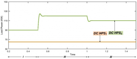
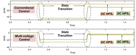
Figure 12 shows load power variations with time in case-I. In state-II and state-III, 30KW and 20KW additional load is connected at HPS2 respectively with no variation in load on HPS1. With conventional control the deviation in voltage of HPS2 are observed as -30V and -20V respectively for state-II and state-III which is beyond prescribed limit. With overloading of 33.33% and 22.22% on HPS2 in state-II and state-III respectively multi-voltage controller shares additional loading among HPS1 and HPS2 in proportion to 42% and 58% respectively.
The multi-voltage controller causes reduction in voltage on HPS1 by 12.58V and 8.39V in state-II and state-III respectively while HPS2 voltage deviated by 17.52V and 11.61V in state-II and state-III respectively. In multi-voltage controller the voltage deviation in both the HPS are shared and under the allowable limit which results in good dynamic performance of the system. Figure 13 represents deviation in voltage for both HPS under conventional and multi-voltage control.
Table 2. %overloading shared in single and multi-frequency control
|
Case |
Time (sec.) |
Overloading |
Single Frequency Control |
Multi-Frequency Control |
|||
|
HPS1 |
HPS2 |
HPS1 |
HPS2 |
HPS1 |
HPS2 |
||
|
I |
t=0.5 |
0KW (0%) |
20KW (16.7%) |
0KW (0%) |
20KW (100%) |
8KW (40%) |
12KW (60%) |
|
t =1 |
0KW (0%) |
10KW (8.3%) |
0KW (0%) |
10KW (100%) |
4KW (40%) |
6KW (60%) |
|
|
II |
t =0.5 |
0KW (0%) |
30KW (25%) |
0KW (0%) |
30KW (100%) |
12KW (40%) |
18KW (60%) |
|
t =1 |
0KW (0%) |
20KW (16.7%) |
0KW (0%) |
20KW (100%) |
8KW (40%) |
12KW (60%) |
|
Figure 12. Load power under case-I for multi-voltage control
Figure 13. DC voltage deviation of HPS1 and HPS2, under case-I for conventional and multi-voltage control
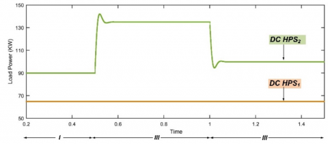
Figure 14. Load power for case-II under multi-voltage control
Figure 15. DC voltage deviation of HPS1 and HPS2, under case-II for conventional and multi-voltage control
5.2.2 Case-I: DC HPS2 low overloading
This case represents heavy overloading condition on one HPS such that the voltage deviation is beyond threshold with conventional controller while multi-voltage controller shares the overloading which results deviation in voltage under the prescribed limit. In this case state-I represent rated state with 90KW load, additional load of 45KW and 10KW is connected on HPS2 in state-II and state-III respectively while HPS1 has constant load of 65KW. Figure 14 represents variation of load power in case-II.
As HPS2 is heavily overloaded in state-II, voltage deviation of HPS2 observed as 45V with conventional controller while in multi-voltage controller the voltage deviations for HPS1 and HPS2 are 18.87V and 26.13V. In state-III additional 10KW load results in voltage deviation on HPS2 as 10V while in multi-voltage controller as load burden is shared among both HPS so voltage deviation on HPS1 and HPS2 are observed as 5.81V and 4.19V respectively. Figure 15 represents deviations on both HPS in state-II and state-III. Total overloading of 50% in state-II and 11.11% in state-III are shared with both HPS to get the deviations within the prescribed limit.
In state-II the voltage deviation observed as 45V which is beyond threshold (+40V) for conventional control while for multi-voltage control the deviations observed in HPS1 and HPS2 are 18.87V and 26.13V which are under the threshold limit. As the voltage deviation in both the HPS with heavy overloading conditions are under the permissible limit with multi-voltage controller so it results in good dynamic performance of the system. Table 3 shows the deviation of voltage for HPS1 and HPS2 with conventional control and multi-voltage control under case-I and case-II.
Results of conventional control indicate that overloading on HPS2 is not shared by HPS1 in conventional control that’s why large voltage deviation is observed in HPS2 while there is no deviation in HPS1. With the application of multi-voltage control the overloading of HPS2 is shared by HPS1 causing a slight voltage deviation in HPS1 also the voltage deviation of HPS2 is reduced as compared to conventional control. Here overloading is shared by HPS1 and HPS2 in proportion to 42% and 58% respectively. This makes the system reliable for variation in loading conditions. Table 4 shows the %overloading shared by both HPS under conventional control and multi-voltage control.
Table 3. Deviation of voltage in volts for individual and multi-voltage control
|
Case |
Time (sec.) |
Conventional Control |
Multi-Voltage Control |
||
|
HPS1 |
HPS2 |
HPS1 |
HPS2 |
||
|
Case-I |
t=0.5 |
0 |
-30 |
-12.58 |
-8.39 |
|
t =1 |
0 |
-20 |
-17.42 |
-11.61 |
|
|
Case-II |
t =0.5 |
0 |
-45 |
-18.87 |
-4.19 |
|
t =1 |
0 |
-10 |
-26.13 |
-5.81 |
|
|
Case |
Time (sec.) |
Overloading |
Single Frequency Control |
Multi-frequency Control |
|||
|
HPS1 |
HPS2 |
HPS1 |
HPS2 |
HPS1 |
HPS2 |
||
|
I |
t=0.5 |
0KW 0% |
30KW (33.33%) |
0KW (0%) |
30KW (100%) |
12.58KW (42%) |
17.42KW (58%) |
|
t =1 |
0KW 0% |
20KW (22.22%) |
0KW (0%) |
20KW (100%) |
8.39KW (42%) |
11.61KW (58%) |
|
|
II |
t =0.5 |
0KW 0% |
45KW (25%) |
0KW (0%) |
45KW (100%) |
18.9KW (42%) |
26.1KW (58%) |
|
t =1 |
0KW 0% |
10KW (16.7%) |
0KW (0%) |
10KW (100%) |
4.2KW (42%) |
5.8KW (58%) |
|
Intertied HPS control has a wide scope in real world due to its extensive applications. Various case studies have been performed to evaluate the efficacy of proposed method. Following conclusions have been drawn from the research.
(I) Till now the research has been focused on single frequency AC HPS and single voltage DC HPS. In this perspective a stand-alone multi-frequency, multi-voltage intertied HPS has been proposed in this study to assure un-interrupted power supply.
(II) It has been revealed from Table 1 that under heavy overloading the deviation in frequency is greater than prescribed limit and shows failure of single frequency control however for multi-frequency control causes the deviation to distribute among HPS. This shows the applicability of the proposed method for heavy loading conditions.
(III) The proposed multi-voltage control offers less deviation in voltage than conventional control with heavy loading condition as seen from Table 3 and achieves better performance in comparison to conventional control.
The proposed multi-frequency, multi-voltage droop control achieves better performance by sharing the overloading in respect to correction factor and assures frequency and voltage deviation under prescribed limit. The proposed method is coordinated, autonomous, simple, reliable and ease of implementation.
|
f |
frequency |
|
Hptotal |
Total load capacity |
|
Hpc |
Critical load capacity |
|
id1ref |
Direct axis reference current of HPS1 |
|
iq1ref |
Quadrature axis reference current of HPS1 |
|
id1 |
Measured direct axis current of HPS1 |
|
iq1 |
Measured quadrature axis current of HPS1 |
|
kp and ki |
PI parameters |
|
Pdc |
Active power of DC HPS |
|
Pac |
Active power of AC HPS |
|
Qrefac_1 |
Reference reactive power of HPS1 |
|
Q1 |
Measured reactive power of HPS1 |
|
r |
Droop coefficient of DC HPS |
|
ud1and uq1 |
Output signals of current control loop |
|
vcb |
Common bus voltage |
|
vrefdc |
reference dc-voltage |
|
vdc |
measured dc-voltages |
|
Greek symbols |
|
|
δv |
Correction factor for voltage |
|
δf |
Correction factor for frequency |
|
αp |
Correction factor for pth AC HPS |
|
αq |
Correction factor for qth DC HPS |
|
Subscripts |
|
|
p |
pth AC HPS |
|
q |
qth DC HPS |
|
* |
Rated values |
|
max |
Maximum value |
|
min |
Minimum value |
|
d |
Direct axis |
|
q |
Quadrature axis |
|
1 |
HPS1 |
|
2 |
HPS2 |
|
‘ |
Normalized value |
|
ac |
AC HPS |
|
dc |
DC HPS |
(1) System Parameters.
|
Controller |
HPS and IPC controller |
|
|
Controlling Parameter |
Value |
|
|
Voltage controller |
DC IPC Kp |
0.6 A/v2 |
|
DC IPC Ki |
50A/v2-s |
|
|
AC IPC Kp |
0.8 A/v |
|
|
AC IPC Ki |
100 A/v-s |
|
|
Current Controller |
DC IPC Kp |
3 v/A |
|
Coordinated Power control |
Coefficient |
α1=4, α2=0.75 |
|
Kp |
0.03 Hz |
|
|
Ki |
3Hz/s |
|
[1] Yadav, A., Srivastava, L. (2014). Optimal placement of distributed generation: An overview and key issues. 2014 International Conference on Power Signals Control and Computations (EPSCICON), Thrissur, pp. 1-6. https://doi.org/10.1109/EPSCICON.2014.6887517
[2] Xiao, H., Luo, A., Shuai, Z., Jin, G., Huang, Y. (2015). An improved control method for multiple bidirectional power converters in hybrid AC/DC microgrid. IEEE Transactions on Smart Grid, 7(1): 340-347. https://doi.org/10.1109/TSG.2015.2469758
[3] Sun, K., Wang, X., Li, Y.W., Nejabatkhah, F., Mei, Y., Lu, X. (2016). Parallel operation of bidirectional interfacing converters in a hybrid AC/DC microgrid under unbalanced grid voltage conditions. IEEE Transactions on Power Electronics, 32(3): 1872-1884. https://doi.org/10.1109/TPEL.2016.2555140
[4] Xia, Y., Peng, Y., Yang, P., Yu, M., Wei, W. (2016). Distributed coordination control for multiple bidirectional power converters in a hybrid AC/DC microgrid. IEEE Transactions on Power Electronics, 32(6): 4949-4959. https://doi.org/10.1109/TPEL.2016.2603066
[5] Peyghami, S., Mokhtari, H., Blaabjerg, F. (2017). Autonomous operation of a hybrid AC/DC microgrid with multiple interlinking converters. IEEE Transactions on Smart Grid, 9(6): 6480-6488. https://doi.org/10.1109/TSG.2017.2713941
[6] Baharizadeh, M., Karshenas, H.R., Guerrero, J.M. (2016). Control strategy of interlinking converters as the key segment of hybrid AC–DC microgrids. IET Generation, Transmission & Distribution, 10(7): 1671-1681. https://doi.org/10.1049/iet-gtd.2015.1014
[7] Jin, Z., Meng, L., Guerrero, J.M., Han, R. (2017). Hierarchical control design for a shipboard power system with DC distribution and energy storage aboard future more-electric ships. IEEE Transactions on Industrial Informatics, 14(2): 703-714. https://doi.org/10.1109/TII.2017.2772343
[8] Unamuno, E., Barrena, J.A. (2015). Hybrid AC/DC microgrids—Part II: Review and classification of control strategies. Renewable and Sustainable Energy Reviews, 52: 1123-1134. https://doi.org/10.1016/j.rser.2015.07.186
[9] ABB project reference: Ross Island, Wind/diesel system Antarctica. ABB, 2013. https://new.abb.com/power-generation/references/ross-island-research-station, accessed on 2 December 2019.
[10] Ding, G., Gao, F., Zhang, S., Loh, P.C., Blaabjerg, F. (2014). Control of hybrid ac/dc microgrid under islanding operational conditions. Journal of Modern Power Systems and Clean Energy, 2(3): 223-232. https://doi.org/10.1007/s40565-014-0065-z
[11] Wu, D., Tang, F., Dragicevic, T., Vasquez, J.C., Guerrero, J.M. (2014). A control architecture to coordinate renewable energy sources and energy storage systems in islanded microgrids. IEEE Transactions on Smart Grid, 6(3): 1156-1166. https://doi.org/10.1109/TSG.2014.2377018
[12] Gupta, P., Swarnkar, P. (2020). Adaptive power sharing in multi‐voltage multi‐frequency intertied hybrid power system. International Transactions on Electrical Energy Systems, e12467. https://doi.org/10.1002/2050-7038.12467
[13] Bidram, A., Davoudi, A. (2012). Hierarchical structure of microgrids control system. IEEE Transactions on Smart Grid, 3(4): 1963-1976. https://doi.org/10.1109/TSG.2012.2197425
[14] Lu, X., Guerrero, J.M., Sun, K., Vasquez, J.C. (2013). An improved droop control method for dc microgrids based on low bandwidth communication with dc bus voltage restoration and enhanced current sharing accuracy. IEEE Transactions on Power Electronics, 29(4): 1800-1812. https://doi.org/10.1109/TPEL.2013.2266419
[15] Nasirian, V., Davoudi, A., Lewis, F.L. (2014). Distributed adaptive droop control for dc microgrids. 2014 IEEE Applied Power Electronics Conference and Exposition - APEC 2014, Fort Worth, TX, pp. 1147-1152. https://doi.org/10.1109/APEC.2014.6803451
[16] Golsorkhi, M.S., Lu, D.C. (2015). A control method for inverter-based islanded microgrids based on V-I droop characteristics. IEEE Transactions on Power Delivery. 30(3): 1196-1204. https://doi.org/10.1109/TPEL.2013.2266419
[17] Sao, C.K., Lehn, P.W. (2008). Control and power management of converter fed microgrids. IEEE Transactions on Power Systems, 23(3): 1088-1098. https://doi.org/10.1109/TPWRS.2008.922232
[18] Lee, C.T., Chu, C.C., Cheng, P.T. (2012). A new droop control method for the autonomous operation of distributed energy resource interface converters. IEEE Transactions on Power Electronics, 28(4): 1980-1993. https://doi.org/10.1109/TPEL.2012.2205944
[19] Majumder, R., Ghosh, A., Ledwich, G., Zare, F. (2009). Angle droop versus frequency droop in a voltage source converter based autonomous microgrid. 2009 IEEE Power & Energy Society General Meeting, Calgary, AB, pp. 1-8. https://doi.org/10.1109/PES.2009.5275987
[20] Li, Y., Li, Y.W. (2011). Power management of inverter interfaced autonomous microgrid based on virtual frequency-voltage frame. IEEE Transactions on Smart Grid, 2(1): 30-40. https://doi.org/10.1109/TSG.2010.2095046
[21] Kim, J., Guerrero, J.M., Rodriguez, P., Teodorescu, R., Nam, K. (2010). Mode adaptive droop control with virtual output impedances for an inverter-based flexible AC microgrid. IEEE Transactions on Power Electronics, 26(3): 689-701. https://doi.org/10.1109/TPEL.2010.2091685
[22] Lin, P., Wang, P., Xiao, J., Wang, J., Jin, C., Tang, Y. (2017). An integral droop for transient power allocation and output impedance shaping of hybrid energy storage system in DC microgrid. IEEE Transactions on Power Electronics, 33(7): 6262-6277. https://doi.org/10.1109/TPEL.2017.2741262
[23] Rokrok, E., Golshan, M.E.H. (2010). Adaptive voltage droop scheme for voltage source converters in an islanded multibus microgrid. IET Generation, Transmission & Distribution, 4(5): 562-578. https://doi.org/10.1049/iet-gtd.2009.0146
[24] Camara, M.B., Dakyo, B., Gualous, H. (2011). Polynomial control method of DC/DC converters for DC-bus voltage and currents management-Battery and supercapacitors. IEEE Transactions on Power Electronics, 27(3): 1455-1467. https://doi.org/10.1109/TPEL.2011.2164581
[25] Wang, P., Jin, C., Zhu, D., Tang, Y., Loh, P. C., Choo, F. H. (2014). Distributed control for autonomous operation of a three-port AC/DC/DS hybrid microgrid. IEEE Transactions on Industrial Electronics, 62(2): 1279-1290. https://doi.org/10.1109/TIE.2014.2347913
[26] Gupta, A., Doolla, S., Chatterjee, K. (2018). Hybrid AC–DC microgrid: systematic evaluation of control strategies. IEEE Transactions on Smart Grid, 9(4): 3830-3843. https://doi.org/10.1109/TSG.2017.2727344
[27] Gupta, N.P., Gupta, P., Masand, D. (2012). Performance evaluation of hybrid active power filter. 2012 International Conference on Communication Systems and Network Technologies, Rajkot, pp. 573-576. https://doi.org/10.1109/CSNT.2012.129
[28] Gupta, N.P., Gupta, P., Masand, D. (2012). Power quality improvement using hybrid active power filter for a DFIG based wind energy conversion system. 2012 Nirma University International Conference on Engineering (NUiCONE), Ahmedabad, pp. 1-6. https://doi.org/10.1109/NUICONE.2012.6493271
[29] Suh, J., Yoon, D.H., Cho, Y.S., Jang, G. (2016). Flexible frequency operation strategy of power system with high renewable penetration. IEEE Transactions on Sustainable Energy, 8(1): 192-199. https://doi.org/10.1109/TSTE.2016.2590939
[30] Tan, K.T., So, P.L., Chu, Y.C., Chen, M.Z.Q. (2013). Coordinated control and energy management of distributed generation inverters in a microgrid. IEEE Transactions on Power Delivery, 28(2): 704-713. https://doi.org/10.1109/TPWRD.2013.2242495
[31] Guerrero, J.M., Matas, J., De Vicuna, L.G.D.V., Castilla, M., Miret, J. (2006). Wireless-control strategy for parallel operation of distributed-generation inverters. IEEE Transactions on Industrial Electronics, 53(5): 1461-1470. https://doi.org/10.1109/TIE.2006.882015
[32] Adhikari, S., Li, F. (2014). Coordinated V-f and P-Q control of solar photovoltaic generators with MPPT and battery storage in microgrids. IEEE Transactions on Smart Grid, 5(3): 1270-1281. https://doi.org/10.1109/TSG.2014.2301157
[33] Han, J., Solanki, S.K., Solanki, J. (2013). Coordinated predictive control of a wind/battery microgrid system. IEEE Journal of Emerging and Selected Topics in Power Electronics, 1(4): 296-305. https://doi.org/10.1109/JESTPE.2013.2282601
[34] Li, X., Guo, L., Li, Y., Hong, C., Zhang, Y., Guo, Z., Li, Y., Hong, C., Zhang, Y., Guo, Z., Huang, D., Wang, C. (2017). Flexible interlinking and coordinated power control of multiple DC microgrids clusters. IEEE Transactions on Sustainable Energy, 9(2): 904-915. https://doi.org/10.1109/TSTE.2017.2765681
[35] Bandar, L.D.N., Mozaffarilegha, M. (2019). Decentralized power management of a hybrid microgrid consisting of solar panel and storage device. European Journal of Electrical Engineering, 21(4): 361-365. https://doi.org/10.18280/ejee.210403
[36] Gupta, P., Swarnkar, P. (2018). Intertied AC-DC hybrid system power sharing through intelligent droop controller. Engineering, Technology & Applied Science Research, 8(1): 2609-2615.
[37] Gupta, P., Swarnkar, P. (2020). Intelligent power sharing control for hybrid system. Intelligent Computing Techniques for Smart Energy Systems, 75-84. https://doi.org/10.1007/978-981-15-0214-9_10