Tao Zhang* | Chuang Lu | Zheng Zheng
© 2020 IIETA. This article is published by IIETA and is licensed under the CC BY 4.0 license (http://creativecommons.org/licenses/by/4.0/).
OPEN ACCESS
Electric Spring (ES) provides one new solution for solving various power quality problems, which caused by intermittent and unsustainable renewable energy sources (RES). But on the user side, traditional controllers have weak robustness and adaptive capacity. For optimizing the dynamic performance of ES, this paper presents an adaptive fuzzy controller (AFC) with a regulatory factor, which makes a fuzzy controller (FC) has stronger robustness and better adaptive capacity. Through making comparison among Quasi-PR controller, FC and AFC in MATLAB in supply voltage fluctuating, load changes suddenly and injecting harmonic, ES’ stronger robustness and better dynamic performance under the control of AFC was certified.
electric spring, voltage stability, regulatory factor, fuzzy controller, adaptive fuzzy controller
Renewable Energy Sources (RES) brings about various power quality problems, such as voltage flicker [1, 2], voltage sag [3] or swell, into small capacities power system like microgrid [4] because of intermittent and unsustainable. Based on the Hook’s low, Hui et al. [5] proposed the concept of Electric Spring (ES) in 2012, which provides a brand new solution for solving various power quality problems.
ES works distributed and independent on the user side, it diminishes the capacity and reduces the costs of energy storage units [6] that used to stabilize output voltage in the supply side. ES is chained together with Non-Critical Loads (NCL), which forms Smart Loads (SL) [7], and SL can stabilize bus voltage by regulating output power when voltage is fluctuating.
After the concept of ES was presented, the feasibility of ES in solving three-phase power unbalance was verified by the simulation experiment [8, 9]. Luo et al. [10] make a comparison between ES and conventional static synchronization compensator, it was verified that ES has better voltage regulated ability and smaller reactive compensation capacity.
Besides, the application of ES in stabilizing frequency [11, 12], power factor correction [13, 14], and harmonic suppression [15] were affirmed. On the other hand, the feasibility of ES in the DC system was verified in [16, 17].
The PI control strategy mostly was used in ES-1 topology [18], which is easy to achieve but has a large limitation; Wang et al. [19] proposes the control algorithm called phase control algorithm, which is suitable for ES-1 and ES-2 topology, the algorithm was used together with Quasi Proportional Resonant(quasi-PR) controller, however, this control structure is overly dependent on circuit parameters and telecommunication, which limits the application of it;
Shuo et al. [20] present the current control strategy based d-q decomposition, this control strategy takes current as control object so that it has great performance in suppressing harmonic, but three PI controllers restrict its application in real life.
Mok et al. [21] propose a Radial-Chordal Decomposition (RCD) control strategy, which can control amplitude and angle of the complex power of SL respectively, obviously, this control method is beneficial to practical application.
The fuzzy control strategy is a kind of intelligent control structures, which combines industrial control experience with fuzzy mathematical theory, it has fast dynamic response speed and strong robustness, and the process of controller design does not need a precise mathematical system model, so the fuzzy controller has great performance in nonlinear and time-varying systems.
Ma et al. [22] introduce fuzzy algorithm and particle swarm optimization (PSO) algorithm into ES control system for putting the advantages like high steady accuracy of PI controller and strong robustness of fuzzy control algorithm together, this adaptive PI controller has better performance but it still has slow dynamic response speed through observing simulation result.
Javaid et al. [23] make a comparison among PI controller, fuzzy PI controller, and fuzzy controller, what can be seen is the fuzzy controller has fast dynamic response speed, smaller overshoot, and bigger steady-state error than PI controller, which makes it suitable for ambiguous environment or industrial condition full of interferences.
ES is nonlinear and the structure with ES belongs to multi-inputs and mono-output systems, the consumer side environment is so complicated that the traditional fuzzy controller’s ability was limited because it cannot change inference rules in real-time.
This paper presented an adaptive fuzzy controller based regulable factor, this controller’s parameters can change in real-time based on circuit condition through a real-time change factor, which optimizes the adaptive capacity of traditional fuzzy controller, through making a comparison with Quasi-PR+P controller and traditional fuzzy controller under the condition of supply voltage fluctuation, load-mutation and harmonic injection in MATLAB/SIMULINK, the better dynamic and static performance and stronger robustness of adaptive fuzzy controller was confirmed.
2.1 Power supply and distribution system model
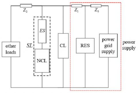
ES’s location in the power grid was shown in Figure 1, what inside the frame with the red imaginary line is the power supply, which was composed of power grid supply and RES like solar and wind energy. Z0, Z1, and Z2 are transmission lines' impedance. There are ES, NCL, Critical Load (CL), and other loads on the user side.
NCL has a wide range of proper functioning voltage, like refrigerators, air conditioners, and so on. SL is made up of ES and NCL, and what shunt with it is CL, CL are voltage-sensitive loads like health-monitoring devices in the hospital or high precision equipment in the mine, voltage fluctuation out of allowed range may shut them down, even cause accidents.
Figure 1. The structure diagram of the power supply and distribution system with ES
All ES take part in regulating bus voltage as a sort of distributed compensator in the user side, the stability of whole power system won’t be impacted if a single one or few ES are broken down, but at the same time, the compensation range of ES was limited by DC-link voltage and normal operating range of NCL, out-of-range voltage fluctuation would cause system instability.
Yin et al. [24] expound ES’s topology and control strategy, and each topology has its advantage. ES-1 topology structure can compensate only for reactive power, its compensation range was analyzed in detail [25, 26]. ES-2 changes the DC-link from capacitor to battery based on ES-1 topology, which makes ES achieve more functions. This paper takes ES-2 as the research object.
2.2 ES-2 topology structure and operating principle
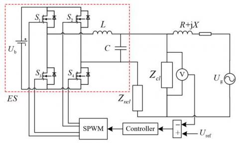
Figure 2 shows the topology structure and control schematic diagram of ES-2, Ug is the supply voltage, R+jX is transmission line impedance, Zcl and Zncl are the impedance of CL and NCL respectively, Uref is the reference voltage of CL, S1~S4 are full-controlled semiconductor devices.
what inside the frame with a red dotted line is the ES-2 topology circuit, L and C are inductor and capacitor of LC low-pass filter respectively. The core of ES-2 is the single-phase full-bridge inverter whose DC-link is the battery whose voltage value is Ub. ES-2 can achieve more function than ES-1, like active compensation, specified power compensation, power factor correction, and so on.
Figure 2. ES-2 topology structure and control schematic diagram
The working process of ES system was stated as follows. While fluctuation of the supply voltage is out of allowed range, Uref would subtract Ucl caught by voltage sensor, which obtains error value, the error signal was disposed by the controller and enter into ‘SPWM’ module so that it can compare with a triangle carrier wave to generate four-channel pulse signal, the pulse signals were used to control four full-controlled semiconductor devices, which converts DC power into AC power, AC power through LC low-pass filter to generate an output voltage Ues that compensates bus voltage.
Finally, Ucl was stabilized into a small range. The relationship among Ues, Ucl and Uncl can be inferred as follows:
${{U}_{cl}}={{U}_{ncl}}+{{U}_{es}}$ (1)
3.1 Controller structure
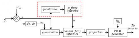
The design of the fuzzy controller with a regulable factor in this paper is based on the Mamdani fuzzy inference model. Figure 3 shows the frame of fuzzy control with a regulable factor.
For resolving the defect that conventional fuzzy controller’s parameters cannot be changed in real-time after its’ parameters are set, this paper adds the fuzzy regulable factor into ES’ control structure as shown in the frame with red dotted lines, the regulable factor named α, which was generated by analyzing error signal e and, α was used to regulate the proportion of two inputs in the module named control fuzzy inference, the whole control structure has the adaptive ability because of α.
Figure 3. The frame of fuzzy control with regulable factor
Reference voltage Uref subtracts Ucl to get error e, e becomes error change rate ec through differential operation module, e was split into two channels, one channel is passing quantization, fuzzification, regulable factor fuzzy inference, and defuzzification to generate α; one channel and ec are passing quantization, fuzzification, control fuzzy inference, defuzzification and proportion to generate control output u, u enter into PWM wave generation module with triangular carrier wave to generate the control signals.
In Figure 3, E, EC is the fuzzy quantity of e and ec respectively, U is the fuzzy quantity output of control fuzzy inference.
The importance of the regulable factor α as follows: when the error is larger, the first mission of the controller is to reduce error, so increasing the proportion of E within inputs; when the error is smaller, the mission of controller is suppressing fluctuation and making system stability, so increasing the proportion of EC. In conclusion, the mathematical expression of control fuzzy inference is:
$U=\alpha E\oplus \frac{1}{\alpha }EC$ (2)
In (2), ‘ $\oplus$’ represents the fuzzy inference process, α was used to regulate the proportion of E and EC. The fuzzy controller can be seen as a non-linear PD controller, which cannot erase error.
3.2 Membership function and fuzzy inference rules
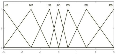
There are two fuzzy inference segments, three inputs’ fuzzification segments and two outputs’ defuzzification segments in the control process, the membership function graph of fuzzification of three inputs as shown in Figure 4.
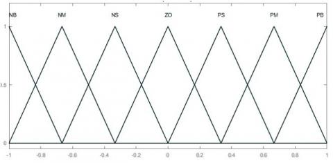
The input membership function is equidistant triangular full overlapping type, which has low resolution when e is a big and high resolution when e is small, the range of input domain is [-3, 3], and the fuzzy subsets is {NB, NM, NS, ZO, PS, PM, PB}, the amplitude limiter will be used to limit the input in permissible range in simulation.
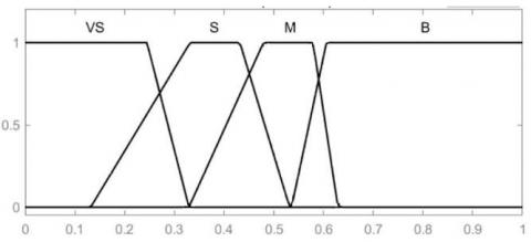
The output membership function graph and inference rules of regulable factor fuzzy inference were displayed in Figure 5 and Table 1, the range of output domain is [0, 1], the fuzzy subsets is {VS, S, M, B}.
The output membership function graphics and inference rules of control fuzzy inference were displayed in Figure 6 and Table 2, the range of output domain is [-1,1], and fuzzy subsets of output are consistent with the input.
In real industrial and life, there are two realization ways to the fuzzy controller, one is using DSP to calculate variable, which also named software implementation; the other is using hardware circuit, like AND circuit and OR circuit formed by operational amplifiers and Multicell-Type Logic circuit, to realize fuzzification, fuzzy inference, and defuzzification, which named hardware implementation.
Figure 4. The membership function graph of three inputs
Figure 5. The output membership function graph of regulable factor α
Table 1. Fuzzy inference rules of ‘regulable factor fuzzy inference’
|
E |
nb |
nm |
ns |
zo |
ps |
pm |
pb |
|
α |
B |
M |
S |
VS |
S |
M |
B |
Figure 6. The output membership function graph of U
Table 2. Fuzzy inference rules of ‘fuzzy control inference’
|
U |
ec |
|
|
|
|
|
|
|
|
NB |
NM |
NS |
ZO |
PS |
PM |
PB |
||
|
e |
NB |
NB |
NB |
NB |
NB |
NB |
NM |
NM |
|
|
NM |
NB |
NB |
NB |
NM |
NM |
NM |
NM |
|
|
NS |
NB |
NB |
NM |
NM |
NM |
NS |
NS |
|
|
ZO |
NB |
NM |
NS |
ZO |
PS |
PM |
PB |
|
|
PS |
PS |
PS |
PM |
PM |
PM |
PB |
PB |
|
|
PM |
PM |
PM |
PM |
PB |
PB |
PB |
PB |
|
|
PB |
PM |
PB |
PB |
PB |
PB |
PB |
PB |
In comparison, the realization of software implementation is easier, but its’ computational speed was limited by processor, so it has a higher delay; the hardware implementation has fast response speed and higher efficiency, but the realization process is more difficult.
4.1 Simulation parameters
The PR controller has great tracking ability to specific sinusoidal signal, but the system with it is so vulnerable, in general, the Quasi-PR controller is commonly used, for faster response speed and smaller steady-state error, the dual-loop control structure with current as inner-loop and voltage as outer-loop was applied.
This paper takes a traditional Quasi-PR+P controller as one comparison object in simulation and takes a conventional fuzzy controller as the other comparison object to observe the adaptive fuzzy controller’s performance.
Taking the circuit in Figure 2 as the basis of the building simulation model, except controller, remaining the circuit parameters the same in ES, circuit parameters were shown in Table 3.
Table 3. Circuit simulation parameters
|
Circuit parameters |
Value |
|
R+jX |
0.1Ω+2.4mH |
|
Zcl |
40Ω |
|
Zncl |
4Ω |
|
L |
3mH |
|
C |
50μF |
|
Ub |
480V |
|
SPWM frequency |
10kHz |
|
RMS of Uref |
220V |
The transfer function of the voltage outer-loop of the quasi-PR+P controller was shown in expression (3), its’ parameters were shown in Table 4, the current inner-loop is P controller, taking the current of the capacitor in low pass filter, the value of the proportional constant is 0.3.
${{G}_{QPR}}(s)={{k}_{\text{p}}}+{{k}_{r}}\frac{2{{\omega }_{c}}s}{s+2{{\omega }_{c}}s+{{\omega }_{0}}}$ (3)
Table 4. Parameters of the quasi-PR controller
|
Parameter |
Value |
|
kp |
5 |
|
kr |
10 |
|
$\omega_{c}$ |
π |
|
$\omega_{0}$ |
100π |
The parameters of the adaptive fuzzy controller were stated in part 3. The conventional fuzzy controller does not have the frame with the red dotted line in Figure 3, the other parameters are consistent with the adaptive fuzzy controller.
4.2 Simulation comparison
4.2.1 Supply voltage Ug sag and swell
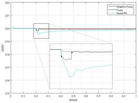
Loads are working normally when Ug is 230.6V. Firstly, comparing the performance when Ug is sagging, when t=0.2s, Ug drops 230.6V to 207.5V, sag proportion is 10%, and the changes of Ucl were shown in Figure 7.
In Figure 7, when the supply voltage Ug is sagging suddenly, the overshoot of quasi-PR+P controller is 0.5V, regulation time is 0.2s, and steady-state error is 0.2V; the overshoot of conventional fuzzy controller is 0.2V, regulation time is 0.02s, and steady-state error is 0.05V; the overshoot of adaptive fuzzy controller is 0.05V, regulation time is 0.014s, and steady-state error is 0.04V. By comparing the quasi-PR+P controller and conventional fuzzy controller, the adaptive fuzzy controller has a smaller overshoot, shorter response time, and smaller error.
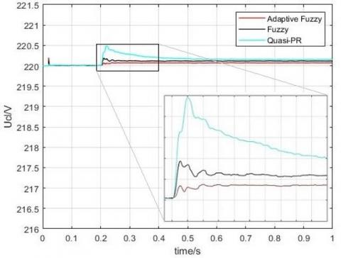
Then do the supply voltage swell experiment, when t=0.2s, supply voltage Ug is rising 230.6V to 253.6V suddenly, the swell proportion is 10%, the Ucl comparison was shown in Figure 8.
From Figure 8, we can see that the adaptive fuzzy controller has the shortest regulation time and the smallest overshoot, its’ steady-state error is 0.075V, which is smaller than 0.13V of conventional fuzzy controller and 0.17V of the quasi-PR+P controller, it is certified that greater dynamic and steady performance of the adaptive fuzzy controller.
Figure 7. Uclcomparison when the supply voltage Ug sag temporarily
Figure 8. Ucl comparison when the supply voltage Ug swell temporarily
4.2.2 CL resistance and property changes suddenly
In real life, the resistance or property of some loads would change constantly, like in the mines, some loads may change the working pattern due to different environment, these non-linear and time-varying loads make the control system must realize control goal quickly in constantly changing system states, which means strong robustness and ability to adapt.
The effect of load variation on voltage regulation was analyzed detailedly based ES-2 topology in [27], it is discovered that the effect of load variation on the performance of electric spring did not vary with the type of load. This paper does the performance evaluation of ES under the control of different controllers.
The simulation parameters of the circuit were shown in Table 3, controllers’ parameters are consistent with part (1), and keep the supply voltage Ug is 210V, which makes ES in capacitive compensation mode.
First, doing the simulation experiment of CL resistance mutation, the CL changes from 40Ω to 80Ω when t=0.1s and changes from 80Ω to 5Ω when t=0.2s, duration time of simulation is 0.3s, the comparison of Ucl under the control of three controllers were shown in Figure 9.
Figure 9. Ucl comparison when the resistance of CL is changing suddenly
Ucl has the smallest steady-state error under the control of the adaptive fuzzy controller during the whole simulation when t=0.2s i.e. the change range of CL resistance is large, the quasi - PR+P controller has the largest overshoot, which may cause system instability.
The adaptive fuzzy controller has the smallest overshoot and steady-state error, and its’ regulate time is shorter than 0.02s, which is better than the quasi-PR+P controller and the conventional fuzzy controller.
Next, comparing the performance of three controllers when CL property is changing suddenly, and keep Ug is 210V, the CL changes from 40Ω to 40Ω+10mH when t=0.1s, and changes from 40Ω+10mH to 40Ω+100μF when t=0.2s, changes of Ucl were shown in Figure 10.
Figure 10. Ucl comparison when the property of CL is changing suddenly
From Figure 10, what can be seen is that Ucl is stable when CL changes from pure resistor to resistor-inductance. When t=0.2s i.e. the CL changes from resistor-inductance to resistor-capacitance, Ucl is changing in a larger range, but the adaptive fuzzy controller has the smallest overshoot and steady-state error that is 0.028V, smaller than 0.12V of the quasi-PR+P controller and 0.035V of the conventional fuzzy controller.
4.2.3 Comparison of suppressing harmonic
Except comparing Ucl while system parameter fluctuation happens, the approach to measuring the controller’s performance can be that observing its’ performance in suppressing harmonic. Next, comparing controllers’ performance when the supply voltage was injected third-harmonic and fifth-harmonic.
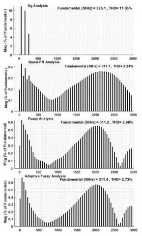
First, keeping the RMS of the supply voltage is 230.6V, then injecting third-harmonic whose value is 23V and fifth-harmonic whose value is 11V into supply voltage, the other parameters are consistent with part (1), simulation time is 0.5s. In Figure 11, the harmonic content of supply voltage Ug and Ucl under the control of three controllers were displayed.
Figure 11. Harmonic content comparison of Ug and Ucl under the control of three controllers
As shown in Figure 11, the harmonic content of supply voltage is 11.06%, and three controllers all can suppress harmonics in the range of 5%, the harmonic content under the control of Quasi-PR+P controller is 2.24%, lower than 2.68% of conventional fuzzy controller and 2.73% of the adaptive fuzzy controller.
Fuzzy controller belongs to the non-linear controller, so the performance of the fuzzy controller is worse than the linear controller in suppressing harmonic, in the adaptive fuzzy controller, because of the regulable factor, inputs of the controller are high-frequency shifting, which may take some higher harmonics in Ucl.
From the controller comparison, while supply voltage fluctuating and CL changing suddenly, we can see that the adaptive fuzzy controller has faster response speed, higher steady-state precision, and stronger resistance capacity to interference.
Meanwhile, there are lower cost and higher efficiency because of the single voltage-loop control structure, which is suitable for the environment with non-linear loads and many interferences. But in suppressing harmonic, fuzzy controller is worse than the traditional linear controller, extra control loop or other harmonic suppress devices may be needed in the fuzzy control system.
This paper presents an adaptive fuzzy control structure with a regulable factor for resolving defects like weak robustness and bad dynamic and steady performance of the traditional controller in ES and introduces its’ structure and parameters.
Through doing simulation and comparison in MATLAB, what can be summarized were stated as follows: (1) the parameter setting process of the fuzzy controller is convenient, it can control object only by converting industrial experience into fuzzy inference rules, and its’ structure is simple, single voltage-loop is more beneficial to the application in real life than dual loop; (2) in comparison of supply voltage and load fluctuation, the adaptive fuzzy controller has stronger robustness and better dynamic and steady-state performance; (3) fuzzy controller does worse than the linear controller in suppressing harmonic because it belongs to the non-linear controller, which is needed to be optimized.
The next step of research is introducing more control strategy or optimization algorithm into the control structure, and simplifying control structure, optimizing the controller’s performance as much as possible on the premise that reducing dependencies to parameters of the circuit as much as possible.
This work was supported in part by the National Natural Science Foundation of China under Grant 61601173, in part by Henan Mine Power Electronics Device and Control Innovative Technology Team under Grant CXTD2017085, and in part by Science and Technology Planning Project of Henan Province of China under Grant 192102210228.
[1] Varetsky, Y., Konoval, V., Seheda, M., Pastuh, O. (2019). Studying voltage fluctuations in microgrid with hybrid renewable energy system. In 2019 IEEE 6th International Conference on Energy Smart Systems (ESS), Kyiv, Ukraine, pp. 239-242. https://doi.org/10.1109/ESS.2019.8764214
[2] Xia, Q., Wang, Z., Liu, F., Li, Y., Peng, Y., Xu, Z. (2017). Study on power quality issues of wind farm. 36th Chinese Control Conference (CCC), Dalian, pp. 10490-10494. https://doi.org/10.23919/ChiCC.2017.8029028
[3] Jia, D., Liu, K., Meng, X., Diao, Y., Zhang, W., Hu, L. (2018). Simulation and evaluation of voltage sag in distribution network with high permeability renewable energy. In 2018 5th International Conference on Information Science and Control Engineering (ICISCE), Zhengzhou, pp. 987-993. https://doi.org/10.1109/ICISCE.2018.00204
[4] Feng, Y.B., Wang, K., Ge, X.H., Zhang, X.S. (2018). System design and control framework analysis of hybrid AC-DC microgrid. Power System Protection and Control, 46(23): 143-150. https://doi.org/10.7667/PSPC171781
[5] Hui, S.Y., Lee, C.K., Wu, F.F. (2012). Electric springs—A new smart grid technology. IEEE Transactions on Smart Grid, 3(3): 1552-1561. https://doi.org/10.1109/TSG.2012.2200701
[6] Wang, M.H., Yang, T.B., Tan, S.C., Hui, S.Y. (2018). Hybrid electric springs for grid-tied power control and storage reduction in AC microgrids. IEEE Transactions on Power Electronics, 34(4): 3214-3225. https://doi.org/10.1109/TPEL.2018.2854569
[7] Liu, Y., Wu, Y.M., Xu, R.M., Jin, M.H., Wan, S.L. (2018). Research on distribution network scheduling with smart load and distributed energy access. Power System Protection and Control, 46(20): 116-123. https://doi.org/10.7667/PSPC171412
[8] Mok, K.T., Ho, S.S., Tan, S.C., Hui, S.R. (2016). A comprehensive analysis and control strategy for nullifying negative-and zero-sequence currents in an unbalanced three-phase power system using electric springs. IEEE Transactions on Power Electronics, 32(10): 7635-7650. https://doi.org/10.1109/TPEL.2016.2636226
[9] Yan, S., Tan, S.C., Lee, C.K., Chaudhuri, B., Hui, S.R. (2014). Electric springs for reducing power imbalance in three-phase power systems. IEEE Transactions on Power Electronics, 30(7): 3601-3609. https://doi.org/10.1109/TPEL.2014.2350001
[10] Luo, X., Akhtar, Z., Lee, C.K., Chaudhuri, B., Tan, S.C., Hui, S.Y.R. (2014). Distributed voltage control with electric springs: Comparison with STATCOM. IEEE Transactions on Smart Grid, 6(1): 209-219. https://doi.org/10.1109/PESGM.2016.7741963
[11] Yang, Y., Tan, S.C., Hui, S.Y. (2016). Voltage and frequency control of electric spring based smart loads. In 2016 IEEE Applied Power Electronics Conference and Exposition (APEC), Long Beach, CA, pp. 3481-3487. https://doi.org/10.1109/APEC.2016.7468368
[12] Wu, T., Xu, X., Chen, L. (2017). Frequency control in microgrids using electric springs. In 2017 China International Electrical and Energy Conference (CIEEC), Beijing, pp. 119-123. https://doi.org/10.1109/CIEEC.2017.8388431
[13] Soni, J., Panda, S.K. (2017). Electric spring for voltage and power stability and power factor correction. IEEE Transactions on Industry Applications, 53(4): 3871-3879. https://doi.org/10.1109/ICPE.2015.7168066
[14] Keykhah, E., Barakati, S.M. (2018). Comprehensive voltage and power factor control strategy for electric spring. Electronics Letters, 54(8): 521-523. https://doi.org/10.1049/el.2018.0268
[15] Wang, Q., Cheng, M., Jiang, Y. (2016). Harmonics suppression for critical loads using electric springs with current-source inverters. IEEE Journal of Emerging and Selected Topics in Power Electronics, 4(4): 1362-1369. https://doi.org/10.1109/JESTPE.2016.2591942
[16] Mok, K.T., Wang, M.H., Tan, S.C., Hui, S.Y. (2015). DC electric springs-An emerging technology for DC grids. In 2015 IEEE Applied Power Electronics Conference and Exposition (APEC), Charlotte, NC, pp. 684-690. https://doi.org/10.1109/APEC.2015.7104424
[17] Wang, Q., Cheng, M., Jiang, Y., Chen, Z., Deng, F., Wang, Z. (2016). DC electric springs with DC/DC converters. In 2016 IEEE 8th International Power Electronics and Motion Control Conference (IPEMC-ECCE Asia), Hefei, China, pp. 3268-3273. https://doi.org/10.1109/IPEMC.2016.7512818
[18] Areed, E.F., Abido, M.A., Al-Awami, A.T. (2017). Switching model analysis and implementation of electric spring for voltage regulation in smart grids. IET Generation, Transmission & Distribution, 11(15): 3703-3712. https://doi.org/10.1049/iet-gtd.2017.0704
[19] Wang, Q., Cheng, M., Chen, Z., Wang, Z. (2015). Steady-state analysis of electric springs with a novel δ control. IEEE Transactions on Power Electronics, 30(12): 7159-7169. https://doi.org/10.1109/TPEL.2015.2391278
[20] Shuo, Y., Tan, S.C., Lee, C.K., Hui, S.R. (2014). Electric spring for power quality improvement. In 2014 IEEE Applied Power Electronics Conference and Exposition-APEC 2014, Fort Worth, TX, USA, pp. 2140-2147. https://doi.org/10.1109/APEC.2014.6803602
[21] Mok, K.T., Tan, S.C., Hui, S.R. (2015). Decoupled power angle and voltage control of electric springs. IEEE Transactions on Power Electronics, 31(2): 1216-1229. https://doi.org/10.1109/TPEL.2015.2424153
[22] Ma, G., Xu, G., Chen, Y., Ju, R. (2018). Voltage stability control method of electric springs based on adaptive PI controller. International Journal of Electrical Power & Energy Systems, 95: 202-212. https://doi.org/10.1016/j.ijepes.2017.08.029
[23] Javaid, M.S., Irshad, U.B., Hussein, A., Abido, M.A. (2017). A novel fuzzy logic controller for smart load voltage regulation. In 2017 6th International Conference on Clean Electrical Power (ICCEP), Santa Margherita Ligure, pp. 620-624. https://doi.org/10.1109/ICCEP.2017.8004753
[24] Yin, F.G., Wang, C. (2019). Review of electric spring: principle, topologies, control and applications. Power System Technology, 43(1): 174-184. https://doi.org/10.13335/j.1000-3673.pst.2018.2040
[25] Yin, F.G., Wang, C. (2019). Analysis of the effective operating range of electric spring based on reactive power compensation. Power System Protection and Control, 47(15): 9-16. https://doi.org/10.19783/j.cnki.pspc.181029
[26] Wei, X., Liu, Y., Zhang, Z., Wang, J. (2016). Steady-state analysis of electric spring for smart grid. In 2016 12th World Congress on Intelligent Control and Automation (WCICA), Guilin, Chian, pp. 905-909. https://doi.org/10.1109/WCICA.2016.7578686
[27] Sen, B., Kailin, R., Sharma, R., Soni, J., Panda, S.K. (2016). Performance evaluation of electric spring: Effect of load variation on voltage regulation. In 2016 IEEE International Conference on Sustainable Energy Technologies (ICSET), Hanoi, pp. 31-35. https://doi.org/10.1109/ICSET.2016.7811752