Marshall Arockia Dass Philip | Peer Fathima Abdul Kareem*
© 2020 IIETA. This article is published by IIETA and is licensed under the CC BY 4.0 license (http://creativecommons.org/licenses/by/4.0/).
OPEN ACCESS
Voltage sags are the major power quality problems and the Dynamic Voltage Restorer (DVR) is considered as an effectual custom power device to attenuate voltage sags. Based on the genesis of voltage sag, there are two types of faults occurring in electrical power distribution systems such as symmetrical and unsymmetrical faults. This paper describes about the various types of voltage sags, Current, Real and Reactive Power in a distribution system, and a brief analysis on pre-fault, during fault and post fault conditions. Various system indices such as Sag Score, Voltage sag energy index, Voltage Sag Lost Energy index, Voltage Sag Severity and Phase Voltage Unbalance Rate have been calculated and analyzed. Also the performance analysis of Total Harmonic Distortion (THD) and Power Factor in distribution system is carried out under fault conditions. The simulation results are carried out in Matlab Simulink environment.
dynamic voltage restorer (DVR), power quality (PQ), single line to ground fault (SLG), double line to ground fault (LLG), triple line to ground fault (LLLG), total harmonics distortion (THD), voltage indices
There has been a lot of surveillance on the field of power quality in the network of power system. The issue of power quality has become decisive, for the companies who manipulate in an exceedingly fierce business domain [1], as a result of which the profitability of the company is adversely affected both in terms of money and time. Hence, there is always clamour for better quality of power. Power quality issues have clinched more interest due to the usage of present day industrial devices such as Programmable Logic Controller, semiconductor devices and electronic devices. These devices are vulnerable to power quality problems such as voltage swell, voltage sag, harmonic distortion, flicker, sustained interruption. Current harmonics and voltage harmonics are created mostly due to these nonlinear loads whose effects are deleterious on consumer’s equipment [2]. Third harmonics caused due to heavy neutral currents, low powerfactor and harmonics present in the voltage are the hurdles related to these devices [1]. Excluding the non-linear loads, some system events may exhibit both the capacitor switching and motor starting cause power quality issues. Nowadays, in developed countries, though generation meets the demand, the quality of supply power is not pure. Hence, extractions of clean energy from the available resources have become a major concern. Many of the custom power controllers have been introduced to shield vulnerable loads against exceptional voltage conditions in the distribution system. The custom power devices such asUnified Power Quality Conditioner, Distribution Static compensator, Dynamic Voltage Restorer have been presented [3-11] in order to enhance the quality of voltage at load side and quality of current at the utility side. Among this, UPQC is however expensive and control scheme is complex and cumbersome to bring in practice. UPQC is the union of series and shunt active filters. The series active filter act as a DVR whereas the shunt active filter act as a DSTATCOM.
The DSTATCOM is a shunt connected compensator which compensates for the current harmonics thereby reduces or compensates the voltage sag/ voltage swell. DVR is a series connected compensator which produces controllable voltage to oppose the short duration voltage disruption. The performance of DVR is an efficacious and cost combative approach to enhance the quality of the voltage at the load side [9-11]. whenever there is occurrence of sag into the system, DVR injects the genuine amount of voltage in series with the supply voltage so as to compensate the voltage sag [12-14]. Installation of first DVR was done in 1996 [15]. DVR was initially propounded to reimburse for the voltage disturbances on distribution system [16]. The aim of DVR was to enhance the voltage quality by calibrating voltage magnitude, phase shift and wave shape [3]. The DVR has the ability of injecting both real and reactive power at the time of voltage sag. LC filter is mostly provided at the output of DVR for suppressing the harmonics from the injected voltage. The intensity of the sag to be mitigated in the load voltage is same design features to be considered while designing the filter parameters [17]. In summation to the voltage swell and voltage sag compensation, DVR can also an effective custom power device in compensating the harmonics, limiting the transient voltage and fault current. The common structure of DVR is composed of voltage source converter, series transformer, DC storage system and a harmonics filter. The DVR must be capable of differentiating between inherent power quality problems and the voltage sags which are need to be compensated [18]. The DVR is truly a nonlinear system due to the existence of power semiconductor switches in the inverter bridge. Power system has become more complex due to the increase of fault current, which may violate the permissible limit, causing damage to the apparatus. Hence circuit breakers are needed to be used having higher breaking current which may be a costly affair [19-26]. The more the fault current, more breaking current capacity should be possessed by the circuit breaker which increases its cost. To overcome these drawbacks, DVR is proposed in this paper.
Several control strategies have been evolved for the mitigation of voltage sag and swell. The differentiation can be done in two groups such as linear and nonlinear controllers. Linear controllers consist of ramp-comparison current regulator, state feedback controllers, synchronous PI regulator, hard switched converter and predictive and dead beat regulator. Nonlinear controllers include the neural network and fuzzy logic based regulator. It is found that the nonlinear controller is more appropriate than that of the linear type [27, 28]. There is various control algorithm presented in the literature for regulation of the DVR. They are differentiated as frequency domain and time domain control algorithms. Some of the frequency domain control algorithm are Fast Fourier transform theory, Fourier series theory, Wavelet transformation theory, Discrete Fourier transform theory, Recursive discrete Fourier transform theory, Empirical decomposition (EMD) transformation theory, Kalman filter-based control algorithm, Stockswell transformation (S-Transform) theory and Hilbert-Huang transformation theory. Some of the time domain control algorithm are Instantaneous reactive power theory (IRPT), also known as α-β theory or PQ theory, d-q theory also known as Synchronous reference frame (SRF) theory, unit template technique or proportional integral controller based theory, Instantaneous symmetrical component (ISC) theory, Neural network theory (Widrow LMS-based Adaline algorithm), Enhanced phase locked loop (EPLL) based control algorithm, single phase active and reactive power theory, single phase SRF theory and adaptive detecting algorithm also known as adaptive interference cancelling theory. Some of the control algorithms mentioned in the recent literature are used for controlling of DVR [29]. To simplify the control algorithm process, SRF theory is suggested for DVR in this paper.
The faults on the power system which gives rise to equal fault currents in the lines with 120 degree displacement is known as symmetrical fault and unequal fault currents in the lines with unequal phase displacement are called unsymmetrical faults. Majority of the system faults are unsymmetrical in nature and classified as single line to ground fault, line to line fault and double line to ground fault. It can occur either by natural disturbances or by manual errors.
In the existing power conditioning works presented in the survey papers explained the voltage sag analysis by varying load in the distribution system. In this paper voltage sag is created by symmetrical and unsymmetrical faults and analyse the various types of voltage sags, current, real and reactive power in a distribution system under pre-fault, during fault and post fault conditions. The simulated results are compared with and without DVR. The paper is structured as follows. Section 2 and 3 describes the DVR and synchronous frame theory concepts. In section 4, various system indices such as sag score, voltage sag energy index, voltage sag lost energy index, voltage Sag Severity and phase voltage unbalance rate are discussed. In section 5, the simulation results of various distribution system parameters are carried out using Matlab Simulink under various fault conditions. The conclusions are presented in section 6.
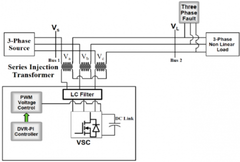
The schematic diagram of a typical DVR structure in distribution system is shown in Figure 1. A Dynamic Voltage Restorer is one of the custom power devices connected in series with electrical power distribution system, which is comprised of four major units namely energy storage device, voltage source inverter, injection transformer and control unit. It is used to inject voltage to maintain terminal voltage at rated magnitude and frequency. If the voltage of DVR is in phase with the line voltage, it will inject active power and the DVR voltage is in phase quadrature with the line voltage then it will inject reactive power. DVR compensates only voltage dip, swell and voltage harmonics.
Figure 1. Schematic diagram of two bus distribution system with DVR
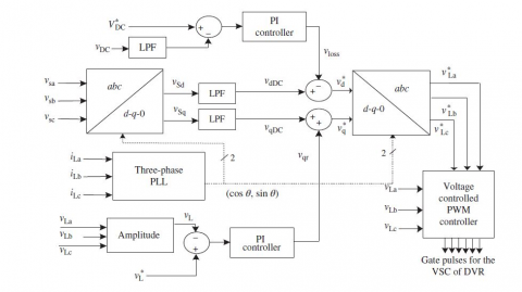
Figure 2 depicts the Synchronous Reference Frame theory control algorithm for DVR. Using the Park’s transformation, the voltage at PCC is transformed to rotating reference frame theory with the help of abc to dqo transformation. Low pass filter is used to reduce the oscillatory components and harmonics of the voltage. The direct and the quadrature axis voltages are:
${{V}_{Sd}}={{V}_{dDC}}+\text{ }{{V}_{dAC}}$ (1)
${{V}_{Sq}}={{V}_{qDC}}+{{V}_{qAC}}$ (2)
In order to attain the good quality of voltage, it is ensured that the voltage at load terminal must be of estimated magnitude and uniform in nature. PI controller is used at the DC bus voltage of DVR and output is assumed as voltage loss.
${{V}_{Loss(n)}}={{V}_{Loss(n-1)}}+{{K}_{p1}}\left( {{V}_{de(n)}}-{{V}_{de(n-1)}} \right)+{{K}_{i1}}{{V}_{de(n)}}$ (3)
where, $V_{d(n)}=V_{D C}^{*}-V_{D C(n)}$ is the error between sensed DC voltage$\left(V_{D C}^{*}\right)$ at the $n^{\text {th }}$ sampling instant. Ki1 and Kp1 are the integral and proportional gains. To maintain the DC bus voltage as constant, the gain values of PI controller is chosen as trial and error method.
Hence the reference direct axis voltage at the load is given by:
$V_{d}^{*}\text{ }=\text{ }{{V}_{dDC}}-\text{ }{{V}_{loss}}$ (4)
Figure 2. Synchronous reference frame (SRF) based DVR
Another PI controller is used to control the amplitude of load terminal voltage (VL) to its reference voltage (VL*). Reactive component of voltage (Vqr) is the output voltage of PI controller. It is used to regulate reference value as:
${{V}_{qr(n)}}={{V}_{qr(n-1)}}+{{K}_{p2}}\left( {{V}_{te(n)}}-{{V}_{te(n-1)}} \right)+{{K}_{i2}}{{V}_{te(n)}}$ (5)
where, $V_{t e(n)}=V_{L}^{*}-V_{L(n)}$, represents error between reference and actual load terminal. Ki1 and kp1 are the integral and proportional gains of the PI controller.
The reference load quadrature axis voltage is
$V_{q}^{*}\text{ }=\text{ }{{V}_{qDC}}+{{V}_{qr}}$ (6)
The reverse park transformation gives the reference load voltages in the abc frame. The difference between sensed load voltage and error load voltage is fed to the PWM controller to produce the gate pulse for Voltage Source Converter (VSC) of the DVR [29].
Voltage Sag indices manifests the voltage sag quality and are vulnerable to any faults occurring in the power distribution systems, as a result of which, they can give reliable feedback on system execution. The following indices are calculated and discussed in the simulation results.
4.1 Detroit Edison Sag Score
This Detroit Edison Sag Score (DESS) is mathematically expressed as [30, 31]:
$DESS=\text{ }1-\frac{{{V}_{A}}+{{V}_{B}}+{{V}_{C}}}{3}$ (7)
The quantities VA, VB, VC are the RMS values in per unit of the phase voltages. This method is simple but has the drawbacks that the voltage sag duration is not considered. After compensation, the good recovered voltage can be achieved if sag score value is near to zero.
4.2 Voltage sag energy
The voltage sag energy is mathematically expressed as [32]:
${{E}_{VS}}=\int_{0}^{T}{{{\left\{ 1-\frac{V(t)}{Vnom} \right\}}^{2}}}dt$ (8)
where, V is the voltage magnitude and Vnom is the nominal voltage and T is the sag duration.
The RMS voltage is assumed constant over the duration of the event. The voltage-sag energy then can be given as:
${{E}_{vs}}=\left[ 1-{{\left( \frac{V}{Vnom} \right)}^{2}} \right]\times 100\times T$ (9)
4.3 Voltage Sag Lost Energy Index (VSLEI)
Lost energy during the sag event is given by this index. In 2000, Thalam proposed this method [33, 34]:
$W={{\left\{ 1-\frac{V}{{{V}_{nom}}} \right\}}^{3.14}}\times T$ (10)
where, T is the sag duration in milliseconds and V is the phase voltage in per unit of nominal voltage. The factor 3.14 raised to the power of voltage is obtained from CBEMA (Computer Business Equipment Manufacturer Association) curve.
Three phase sag events can be given as
$W={{\left\{ 1-\frac{{{V}_{a}}}{{{V}_{nom}}} \right\}}^{3.14}}\times {{T}_{a}}+{{\left\{ 1-\frac{{{V}_{b}}}{{{V}_{nom}}} \right\}}^{3.14}}\times {{T}_{b}}+{{\left\{ 1-\frac{{{V}_{c}}}{{{V}_{nom}}} \right\}}^{3.14}}\times {{T}_{c}}$ (11)
where, Va, Vb and Vc are the respective three phase voltages and Ta, Tb and Tc are respective duration in milliseconds.
4.4 Phase voltage unbalance rate
National Electrical Manufacturers Association (NEMA) has defined voltage unbalance rate in percent in the Standards Publication no. MG 1-1993 as [35]:
$PVUR\text{ }=\frac{Maximum\text{ }Phase\text{ }Voltage\text{ }deviation\left( {{V}_{d\max }} \right)}{Average\text{ }phase\text{ }voltage\text{ }\left( {{V}_{avg}} \right)}$ (12)
where, Vdmax represents phase voltage deviation from the average phase voltage (Vavg). The main reason of voltage unbalance is single phase loads present in three-phase circuits. Ripples present in the power supply are the consequence of voltage unbalance due to which there will be unwanted heating of the equipment. Also, there will be decrease in Mean time Between Failure (MTBF) on all strained devices. The causes of voltage unbalance should be restricted between 1% and 5% to decrease the equipment failure [33].
4.5 Voltage sag severity
Voltage sag Severity is mathematically expressed as [34]:
${{S}_{e}}=\frac{1-U}{1-{{U}_{\text{curve }}}(d)}$ (13)
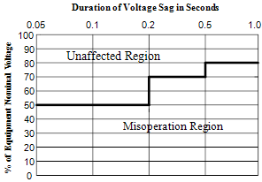
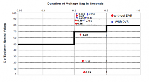
where, U is the retained voltage, d is the duration of the event and Ucurve(d) is the retained voltage of the reference curve for same duration which is shown in Table 1 and Figure 3. Voltage sag severity will be unity when event is on the reference curve. The Index is less than one if the event is above the reference curve, while the index is greater than one if the event is below reference curve [36]. Voltage sag severity algorithm is developed using the Semiconductor Equipment and Materials Institute (SEMI) curve [37] as a reference for the calculation of voltage sag severity. If the voltage sag is inside the boundary then the semiconductor equipment will not get damaged and event is counted based on the System average RMS variation frequency index (SARFI) -SEMI voltage sag severity algorithm shown in Table 1.
Table 1. SARFI-SEMI voltage-sag severity algorithm
|
Ucurve |
Duration range (d) |
Voltage Sag Severity (Se) Calculation |
|
0.0 pu |
d≤20ms |
${{\text{S}}_{\text{e}}}\text{=}\frac{\left( \text{1-U} \right)}{\left( \text{1-0}\text{.0} \right)}\text{=1-U}$ |
|
0.5 pu |
20ms<d≤200ms |
${{\text{S}}_{\text{e}}}\text{=}\frac{\left( \text{1-U} \right)}{\left( \text{1-0}\text{.5} \right)}\text{=2(1-U)}$ |
|
0.7 pu |
200ms<d≤500ms |
${{\text{S}}_{\text{e}}}\text{=}\frac{\left( \text{1-U} \right)}{\left( \text{1-0}\text{.7} \right)}\text{=3}\text{.3(1-U)}$ |
|
0.8 pu |
500ms<d≤10s |
${{\text{S}}_{\text{e}}}\text{=}\frac{\left( \text{1-U} \right)}{\left( \text{1-0}\text{.8} \right)}\text{=5(1-U)}$ |
|
0.9 pu |
10s<d |
${{\text{S}}_{\text{e}}}\text{=}\frac{\left( \text{1-U} \right)}{\left( \text{1-0}\text{.9} \right)}\text{=10(1-U)}$ |
Figure 3. SEMI voltage sag curve
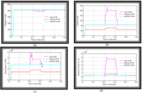
The performance of three different faults such as Case I:SLG, Case II:LLG, and Case III: LLLG are investigated using two bus distribution system shown in Figure 1. The parameters of three phase system and DVR have been enlisted in Table 2. Simulation is carried out by creating a fault between 0.2 to 0.3 seconds at bus 2 in the distribution line. Three conditions such as Pre fault, fault without DVR and fault with DVR are analysed. Table 3 and Figures 4-9 show the system parameters such as voltage, current, real and reactive power, for both Bus 1 and Bus 2for three different faults.
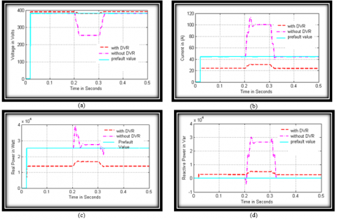
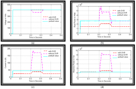
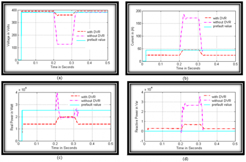
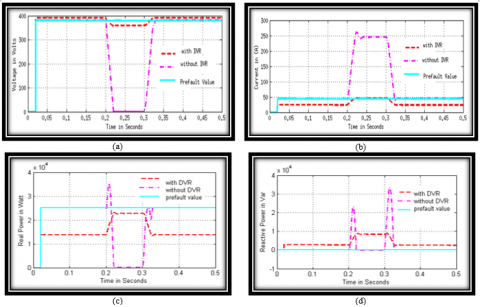
It is observed from Table 3 and Figure 4a,6a& 8a that the voltage sagat bus1 without DVR during fault condition is low in case I(390V), moderate in case II(367V) and high in case III(345V). By the insertion of DVR the sag value in case I is (411.2V), case II(410V) and case III (408). From Figure 5a,7a & 9a the Load voltage sag without DVR observed in three cases are 254V, 127V, and 0.24V respectively. By insertion of DVR, it is observed in three cases are 380V,369V, and 358V respectively. Hence by comparing the results, it is noticed that Bus1 and Bus2 voltages are maintained to their nearest nominal value after insertion of DVR.
It is also observed from Table 3 and Figure 4b-9b the fault current without DVR is low in case I(100A), moderate in Case II (171.5A) and high in case III (245A). After implementing DVR, the fault current in case I is reduced to (29.2A), in case II it is (36A) and in case III it is (43.5A). Hence by comparing the results, it is observed that the circuit breaker rating can be reduced by insertion of DVR in the distribution line. Also, it is demonstrated that reactive power injecting device suppresses the fault current near to the pre fault value (44A) in case III but not to the exact nominal value in case I & II. Hence DVR effectively compensates only the voltage related power quality issues. For current related issues, UPQC can be a good choice as it gives one shot compensation for all the power quality problems in electrical power distribution system.
It is observed From Table 3 and Figure 4c, 6c & 8c, that the real power at bus 1 without DVR during fault conditions, increases slightly in case I (48 KW), Moderate in case II (60KW) and high in case III(70 KW). By insertion of DVR, the real power at the time of fault is reduced to 16.5 KW in case I, 19.5 KW in case II and 23KW in case III. From Figure 5c, 7c, & 9c the load real power at bus2 without DVR observed in three cases are 39.5KW, 39.7KW & 35 KW. By insertion of DVR, Real Power at the time of fault is reduced in three cases are 15.6 KW, 18.4KW & 21.2KW. Figure 4d, 6d & 8d, shows the reactive power at bus1 without DVR during fault conditions increases slightly in case I (45 KVAR), Moderate in case II (88.4KVAR) and high in case III (113 KVAR). By insertion of DVR, the reactive power at the instant of fault is reduced to 7.4 KVAR in case I, 10.4 KVAR in case II and 13.5 KVAR in case III. From Figure 5d, 7d, & 9d the load reactive power at bus2 without DVR observed in three cases are 30KVAR, 35.4KVAR & 33 KVAR. By insertion of DVR, Reactive Power transient reduced in three cases are 5.8 KVAR, 8KVAR & 10KVAR. By comparing the results, it is observed that real and reactive power are exceeding the pre-fault values due to symmetrical and unsymmetrical faults occurring in the distribution systems. By insertion of DVR the transient response of real and reactive power is suppressed near to the nominal value, which will eliminate the need of relays and circuit breakers.
Table 4 shows the various system indices at Bus 1and Bus 2. The sag score without DVR was increased slightly in case I(6.02% & 38.79%) average for case II(11.56%& 69.39%) and high for case III(16.86%& 99.9%). After insertion of DVR, sag score values were reduced in all three cases i.e. CaseI(0.915% & 8.43%), Case II (1.20% & 11.08%), Case III (1.68% & 13.73%). Hence the recommended device was capable to attain the essential target while reducing the harmonic distortions present in the voltage. Also voltage sag severity is calculated using Table 1 and the respective values are tabulated in Table 4. Voltage sag severity values plotted with SARFI SEMI reference curve is shown in Figure 13. It is observed that without DVR total of six values have been plotted out of which three values are below the reference curve. Hence the information technology equipment like Switching Mode Power Supply, Laptop, Mobile Phones and Mobile charger are prone to get damaged. Whereas with DVR, all six values are within the reference curve hence there would not be any damage to the equipment.
Also it is observed that the percentages of phase voltage unbalance rate are within the IEEE standard 112-1991 recommendations by insertion of DVR.
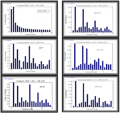
The THD Levels of two buses are compared by using Diode rectifier load for three different faults, the details of which are given in Table 5-6 and Figure 10-12. It is observed that the value of THD at the Bus1 is less as compared to the Bus2; this is because generator is connected at the bus1 when DVR is off. During the fault condition at Bus2, the voltage THD is exceeding 100% in all three cases while at Bus1, the voltage THD is less compared to the pre-fault and post fault conditions because the Non linear load is isolated from distribution system. Considering the IEEE standard 519 -2014, it is clear that the THDV percentages are within the prescribed limits after insertion of DVR for all the three cases.
Powerfactor is calculated at Bus 1 & Bus 2 as shown in Table 7. At the time of fault, DVR maintains the load power factor near to unity for case I(0.93) and case II(0.92). In case III, without DVR, load side power factor is 0.729 as a result of sustained interruption and it is overcome by insertion of DVR which raises the power factor to 0.9.
Table 2. Parameters of the three phase system and DVR
|
Parameter |
Value |
|
Supply Voltage |
415 V |
|
Frequency |
50 Hz |
|
Line resistance |
0.632 Ω |
|
Line Inductance |
4 mH |
|
Injection transformer turns ratio |
1:1 |
|
Injection transformer |
25 KVA |
|
Switching Frequency |
1 kHz |
|
Load Real Power |
20 KW |
|
Load Inductive Reactive Power |
100 VAR |
|
Filter inductance |
1 mH |
|
Filter capacitance |
10 µf |
|
DC link capacitor |
3000 µf |
Table 3. Performance analysis of various distribution system parameters
|
System Parameters |
Pre-fault |
Case I |
Case II |
Case III |
||||
|
With DVR |
Without DVR |
With DVR |
Without DVR |
With DVR |
Without DVR |
|||
|
Bus 1 |
Voltage(Volts) |
413 |
411.2 |
390 |
410 |
367 |
408 |
345 |
|
Current(Amps) |
44 |
29.2 |
100 |
36 |
171.5 |
43.5 |
245 |
|
|
Bus 2 |
Voltage(Volts) |
380 |
380 |
254 |
369 |
127 |
358 |
0.24 |
|
Current(Amps) |
44 |
29.2 |
100 |
36 |
171.5 |
43.5 |
245 |
|
|
Bus 1 |
Real Power (KW) |
27 |
16.5 |
48 |
19.5 |
60 |
23 |
70 |
|
Reactive Power (KVAR) |
3.8 |
7.4 |
45 |
10.4 |
88.4 |
13.5 |
11.3 |
|
|
Bus 2 |
Real Power (KW) |
25 |
15.6 |
39.5 |
18.4 |
39.7 |
21.2 |
35 |
|
Reactive Power (KVAR) |
0.126 |
5.8 |
30 |
8 |
35.4 |
10 |
33 |
|
Table 4. Performance analysis of various indices at Bus 1 and Bus 2
|
|
Case I |
Case II |
Case III |
||||
|
With DVR |
Without DVR |
With DVR |
Without DVR |
With DVR |
Without DVR |
||
|
Sag score(%) |
Bus 1 |
0.915 |
6.02 |
1.20 |
11.56 |
1.68 |
16.86 |
|
Bus 2 |
8.43 |
38.79 |
11.08 |
69.39 |
13.73 |
99.9 |
|
|
Voltage Sag Lost Energy Index |
0.000119 |
0.01845 |
0.000283 |
0.2288 |
0.0008129 |
1.122 |
|
|
0.127 |
12.838 |
0.3003 |
63.55 |
0.588 |
299.45 |
||
|
Voltage sag Energy Index(EVS) |
0.0869 |
1.08 |
0.145 |
2.10 |
0.241 |
3.022 |
|
|
1.62 |
6.25 |
2.09 |
9.06 |
2.56 |
9.99 |
||
|
Voltage Sag severity |
0.033 |
0.231 |
0.066 |
0.39 |
0.066 |
0.561 |
|
|
0.264 |
1.28 |
0.39 |
2.27 |
0.455 |
3.29 |
||
|
PVUR(%) |
0.43 |
5.57 |
0.73 |
11.14 |
1.21 |
16.46 |
|
|
0.0 |
33.16 |
2.89 |
66.58 |
5.78 |
99.9 |
||
Table 5. THD Analysis in distribution system at prefault and during fault
|
%THD |
Pre-FAULT |
During Fault |
||||||
|
Case I |
Case II |
Case III |
||||||
|
With DVR |
Without DVR |
With DVR |
Without DVR |
With DVR |
Without DVR |
With DVR |
Without DVR |
|
|
VTHDa1 |
0.62 |
4.88 |
0.36 |
2.00 |
0.13 |
2.00 |
0.24 |
2.00 |
|
VTHDb1 |
0.64 |
4.70 |
0.67 |
6.14 |
0.13 |
2.25 |
0.24 |
2.25 |
|
VTHDc1 |
0.70 |
4.61 |
0.76 |
6.31 |
0.14 |
1.79 |
0.47 |
3.59 |
|
VTHDa2 |
3.23 |
29.24 |
1.84 |
459.30 |
0.68 |
464.84 |
1.21 |
471.72 |
|
VTHDb2 |
3.34 |
28.24 |
3.47 |
33.21 |
0.70 |
477.43 |
1.21 |
486.94 |
|
VTHDc2 |
3.63 |
27.69 |
3.95 |
39.92 |
0.70 |
9.24 |
2.42 |
479.42 |
Table 6. THD analysis in distribution system after clearing fault
|
%THD |
After fault clearance |
|||||
|
Case I |
Case II |
Case III |
||||
|
With DVR |
Without DVR |
With DVR |
Without DVR |
With DVR |
Without DVR |
|
|
VTHDa1 |
0.62 |
10.74 |
0.91 |
11.06 |
1.56 |
5.26 |
|
VTHDb1 |
0.65 |
10.62 |
0.87 |
10.97 |
1.63 |
5.05 |
|
VTHDc1 |
0.68 |
10.61 |
0.87 |
10.92 |
1.64 |
5.05 |
|
VTHDa2 |
3.20 |
64.31 |
4.71 |
66.22 |
8.07 |
31.56 |
|
VTHDb2 |
3.36 |
63.64 |
4.50 |
65.76 |
8.44 |
30.33 |
|
VTHDc2 |
3.53 |
63.55 |
4.53 |
65.41 |
8.51 |
30.31 |
Table 7. Powerfactor calculation at Bus 1 and Bus 2
|
BUS |
Case I |
Case II |
Case III |
|||
|
With DVR |
Without DVR |
With DVR |
Without DVR |
With DVR |
Without DVR |
|
|
Bus 1 |
0.91 |
0.729 |
0.88 |
0.56 |
0.86 |
0.45 |
|
Bus 2 |
0.93 |
0.796 |
0.92 |
0.74 |
0.90 |
0.727 |
Figure 4. a) Voltage, b) Current, c) Real Power, d) Reactive Power during single line to ground fault at Bus 1
Figure 5. a) Voltage, b) Current, c) Real Power, d) Reactive Power during single line to ground fault at Bus 2
Figure 6. a) Voltage, b) Current, c) Real Power, d) Reactive Power during double line to ground fault at Bus 1
Figure 7. a) Voltage, b) Current, c) Real Power, d) Reactive Power during double line to ground fault at Bus 2
Figure 8. a) Voltage, b) Current, c) Real power, d) Reactive power during three phase to ground fault at Bus 1
Figure 9. a) Voltage, b) Current, c) Real Power, d) Reactive Power during three phase to ground fault at Bus 2
Figure 10. THD measurement at bus 1- Prefault conditions
Figure 11. THD measurement at Bus 1 during single line to ground fault conditions
Figure 12. THD Measurement at Bus 1- Post Fault conditions
Figure 13. SARFI-SEMI voltage-sag severity curve
This paper describes about the analysis of various types of voltage sags, current, real and reactive power in a distribution system with DVR under pre-fault, during fault and post fault conditions. Various system indices such as sag score, voltage sag energy index, voltage sag lost energy index, voltage sag severity and phase voltage unbalance rate have been calculated and analyzed. The performance analysis of Total Harmonic Distortion (THD) and powerfactor in distribution system is carried out under various fault conditions. Also the withstanding capability of the equipment is tested using SEMI curve. The results presented in the simulation clearly demonstrate the potency of DVR in compensating voltage sag, suppressing fault current, real and reactive power at the time of transients. Moreover, there was an improvement in power factor after insertion of DVR. Hence, DVR works well in both symmetrical and unsymmetrical fault conditions in electrical distribution systems.
|
Vsd |
Direct axis source voltage |
|
Vsq |
Quadrature axis source voltage |
|
VdDC |
Direct axis DC bus voltage |
|
VdAC |
Direct axis AC voltage |
|
Vsd |
Direct axis source voltage |
|
VL |
Load Terminal Voltage |
|
$\text{V}_{\text{q}}^{*}$ |
Reference load quadrature axis voltage |
|
Vqr |
Reactive component of voltage |
|
Vloss |
Voltage Loss |
|
U |
Retained Voltage |
|
Ucurve |
Retained Voltage of the reference curve |
|
d |
Duration |
|
Vdmax |
Maximum phase voltage deviation |
|
Vavg |
Average Phase Voltage |
|
Vnom |
Nominal Voltage |
|
Va,Vb,Vc |
Phase a Voltage, Phase b Voltage, Phasse c Voltage |
|
EVS |
Voltage Sag Energy |
|
Kp |
Proportional Gain |
|
Ki |
Integral Gain |
[1] SasiKiran, P., Manohar, T.G. (2018). UKF based estimation approach for DVR control to compensate voltage swell in distribution systems. Ain Shams Engineering Journal, 9(4): 441-453. https://doi.org/10.1016/j.asej.2016.02.001
[2] Saeed, A.M., Aleem, S.H.A., Ibrahim, A.M., Balci, M.E., El-Zahab, E.E. (2016). Power conditioning using dynamic voltage restorers under different voltage sag types. Journal of Advanced Research, 7(1): 95-103. https://doi.org/10.1016/j.jare.2015.03.001
[3] Fujita, H., Akagi, H. (1998). The unified power quality conditioner: The integration of series-and shunt-active filters. IEEE Transactions on Power Electronics, 13(2): 315-322. https://doi.org/10.1109/63.662847
[4] Graovac, D., Katic, V., Rufer, A. (2000). Power quality compensation using universal power quality conditioning system. IEEE Power Engineering Review, 20(12): 58-60. https://doi.org/10.1109/39.890381
[5] Mishra, M.K., Ghosh, A., Joshi, A. (2003). Operation of a DSTATCOM in voltage control mode. IEEE Transactions on Power Delivery, 18(1): 258-264. https://doi.org/10.1109/TPWRD.2002.807746
[6] Ledwich, G., Ghosh, A. (2002). A flexible DSTATCOM operating in voltage or current control mode. IEE Proceedings-Generation, Transmission and Distribution, 149(2): 215-224. https://doi.org/10.1049/ip-gtd:20020009
[7] Sensarma, P.S., Padiyar, K.R., Ramanarayanan, V. (2001). Analysis and performance evaluation of a distribution STATCOM for compensating voltage fluctuations. IEEE Transactions on Power Delivery, 16(2): 259-264. https://doi.org/10.1109/61.915492
[8] Escobar, G., Stankovic, A.M., Mattavelli, P. (2004). An adaptive controller in stationary reference frame for D-statcom in unbalanced operation. IEEE Transactions on Industrial Electronics, 51(2): 401-409. https://doi.org/10.1109/TIE.2004.825270
[9] Ghosh, A., Jindal, A.K., Joshi, A. (2004). Design of a capacitor-supported dynamic voltage restorer (DVR) for unbalanced and distorted loads. IEEE Transactions on Power Delivery, 19(1): 405-413. https://doi.org/10.1109/TPWRD.2003.820198
[10] Nielsen, J.G., Newman, M., Nielsen, H., Blaabjerg, F. (2004). Control and testing of a dynamic voltage restorer (DVR) at medium voltage level. IEEE Transactions on Power Electronics, 19(3): 806-813. https://doi.org/10.1109/TPEL.2004.826504
[11] Choi, S.S., Li, B.H., Vilathgamuwa, D.M. (2002). Design and analysis of the inverter-side filter used in the dynamic voltage restorer. IEEE Transactions on Power Delivery, 17(3): 857-864. https://doi.org/10.1109/TPWRD.2002.1022815
[12] Ho, C.N.M., Chung, H.S.H. (2010). Implementation and performance evaluation of a fast dynamic control scheme for capacitor-supported interline DVR. IEEE Transactions on Power Electronics, 25(8): 1975-1988. https://doi.org/10.1109/TPEL.2010.2044587
[13] Goharrizi, A.Y., Hosseini, S.H., Sabahi, M., Gharehpetian, G.B. (2011). Three-phase HFL-DVR with independently controlled phases. IEEE Transactions on Power Electronics, 27(4): 1706-1718. https://doi.org/10.1109/TPEL.2011.2159396
[14] Ghosh, A., Jindal, A. K., Joshi, A. (2004). Design of a capacitor-supported dynamic voltage restorer (DVR) for unbalanced and distorted loads. IEEE Transactions on Power Delivery, 19(1): 405-413. https://doi.org/10.1109/TPWRD.2003.820198
[15] Nielsen, J.G., Newman, M., Nielsen, H., Blaabjerg, F. (2004). Control and testing of a dynamic voltage restorer (DVR) at medium voltage level. IEEE Transactions on Power Electronics, 19(3): 806-813. https://doi.org/10.1109/TPEL.2004.826504
[16] Sadigh, A.K., Dargahi, V., Corzine, K. (2016). New configuration of dynamic voltage restorer for medium voltage application. In 2016 IEEE Applied Power Electronics Conference and Exposition (APEC), Long Beach, CA, pp. 2187-2193. https://doi.org/10.1109/APEC.2016.7468170
[17] Li, B.H., Choi, S.S., Vilathgamuwa, D.M. (2001). Design considerations on the line-side filter used in the dynamic voltage restorer. IEE Proceedings-Generation, Transmission and Distribution, 148(1): 1-7. https://doi.org/10.1049/ip-gtd:20010017
[18] Kanakaraj, M., Thirukkovai, S. (2012). Voltage sag/swell compensation using fuel cell fed inverter based dynamic voltage restorer. In IEEE-International Conference on Advances in Engineering, Science and Management (ICAESM-2012), pp. 176-182.
[19] Mahmoudian, A., Niasati, M., Khanesar, M.A. (2017). Multi objective optimal allocation of fault current limiters in power system. International Journal of Electrical Power & Energy Systems, 85: 1-11. http://dx.doi.org/10.1016/j.ijepes.2016.06.013
[20] Justo, J.J., Mwasilu, F., Jung, J.W. (2015). Doubly-fed induction generator based wind turbines: A comprehensive review of fault ride-through strategies. Renewable and Sustainable Energy Reviews, 45: 447-467. http://dx.doi.org/10.1016/j.rser.2015.01.064
[21] Su, C.L., Teng, J.H. (2007). Economic evaluation of a distribution automation project. IEEE Transactions on Industry Applications, 43(6): 1417-1425. http://dx.doi.org/10.1109/TIA.2007.908192
[22] Fathabadi, H. (2016). Novel filter based ANN approach for short-circuit faults detection, classification and location in power transmission lines. Electrical Power and Energy Systems, 74: 374-383. https://doi.org/10.1016/j.ijepes.2015.08.005
[23] Bose, B.K. (2007). Modern Power Electronics and Drives. Prentice-Hall.
[24] Wang, J., Zhong, H., Xia, Q., Kang, C. (2017). Optimal transmission conversion from alternating current to high voltage direct current transmission systems for limiting short circuit currents. Energy, 118: 545-555. https://doi.org/10.1016/j.energy.2016.10.071
[25] Messalti, S., Gherbi, A., Belkhiat, S. (2013). Artificial neural networks for assessment power system transient stability with TCVR. Journal of Electrical Engineering, 13: 76-82.
[26] Mathur, A., Pant, V., Das, B. (2015). Unsymmetrical short-circuit analysis for distribution system considering loads. International Journal of Electrical Power & Energy Systems, 70: 27-38. https://doi.org/10.1016/j.ijepes.2015.02.003
[27] Omar, R., Rahim, N.A. (2009). Implementation and control of a dynamic voltage restorer using Space Vector Pulse Width Modulation (SVPWM) for voltage sag mitigation. In 2009 international conference for technical postgraduates (TECHPOS), Kuala Lumpur, pp. 1-6. https://doi.org/10.1109/TECHPOS.2009.5412062
[28] Nielsen, J.G., Blaabjerg, F., Mohan, N. (2001). Control strategies for dynamic voltage restorer compensating voltage sags with phase jump. In APEC 2001. Sixteenth Annual IEEE Applied Power Electronics Conference and Exposition (Cat. No. 01CH37181), Anaheim, CA, USA, pp. 1267-1273. https://doi.org/10.1109/APEC.2001.912528
[29] Chandra, A., Singh, B., Al-Haddad. K. (2014). Power Quality: Problems and Mitigation Techniques. Wiley Publisher.
[30] Thallam, R.S., Heydt, G.T. (2000). Power acceptability and voltage sag indices in the three phase sense. In 2000 Power Engineering Society Summer Meeting (Cat. No. 00CH37134), Seattle, WA, pp. 905-910. https://doi.org/10.1109/PESS.2000.867482
[31] Ghosh, A., Ledwich, G. (2012). Power Quality Enhancement Using Custom Power Devices. Springer Science & Business Media.
[32] Bollen, M.H.J. (2000). Voltage sag indices - Draft 1.1", with contribution from D. Sabin. IEEE Panel on Voltage Sag Indices.
[33] Bollen, M.H., Sabin, D.D., Thallam, R.S. (2003). Voltage-sag indices-recent developments in IEEE PI564 task force. CIGRE/IEEE PES International Symposium Quality and Security of Electric Power Delivery Systems, 2003. CIGRE/PES 2003, Montreal, Quebec, Canada, pp. 34-41. https://doi.org/10.1109/QSEPDS.2003.159792
[34] Caramia, P., Carpinelli, G., Verde, P. (2009). Power Quality Indices in Liberalized Markets. John Wiley & Sons.
[35] IEEE standard, 112-1991-IEEE standard test procedure for polyphase induction motors and generators. IEEE Std 112-1991. https://doi.org/10.1109/IEEESTD.1991.114383
[36] Pasific Gas and Electric Company. (1999). Voltage Tolerance Boundary report.
[37] SEMI-F47. Voltage sag Immunity standard. https://www.semi.org/en/semi-f47-voltage-sag-immunity-standard-reapproved, accessed on December 22, 2019.