Yesenia Reyes Severiano | Jesús Aguayo Alquicira | Susana E. De León Aldaco* | Luis Mauricio Carrillo Santos
© 2020 IIETA. This article is published by IIETA and is licensed under the CC BY 4.0 license (http://creativecommons.org/licenses/by/4.0/).
OPEN ACCESS
Currently, multilevel inverters with an induction motor as a load are widely used in the industry. Therefore, there has been an increase in the number of studies related to the analysis of the advantages and disadvantages that are presented in the set: multilevel inverter + induction motor (MLI+IM). Exist several multilevel inverter topologies and different modulation techniques for these inverters, so it is very difficult to select the most suitable combination to improve the operating conditions of the set. This paper presents a comparative analysis of the behavior of the electrical and mechanical parameters in the set: multilevel inverter + induction motor, using four different pulse width modulation techniques to generate the switching states for the power semiconductor devices in a three-phase, seven-level cascade multilevel inverter. The objective of the comparison is to identify the modulation strategy with the best performance for the conditions established in this study.
cascaded, modulation technique, modulation index, multilevel inverter, total harmonic distortion
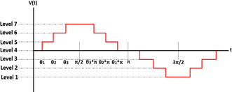
Induction motors are widely used in industry, they are used to drive machine tools, forklifts, elevators, electric cranes, conveyor belts to move parts, and other applications; in certain applications, it is required to vary the speed of the induction motor. A viable and economical solution for achieving motor speed variation is the use of power electronics. DC-to-AC power converters also called inverters. The inverters, according to their topology, can be conventional or multilevel [1, 2]. Figure 1 shows the waveform of the output voltage signal generated by a multilevel inverter.
The multilevel topology has as a feature that generates an output voltage with a stepped waveform, from a DC input voltage.
In multilevel inverters, the output voltage has a harmonic content value that depends on the number of levels provided by the inverter, i.e. the higher the number of voltage levels, the lower the content. The number of levels depends on the modulation technique used to generate the switching states of the power circuit switches [3, 4].
Figure 1. Stepped voltage waveform generated by the multilevel inverter
Figure 2. Classification of modulation techniques
Multilevel inverters are divided into three main topologies:
I: Flying Capacitor Multilevel Inverter, FCMLI
II: Diode Clamped Multilevel Inverter, DCMLI
III: Cascaded Multilevel Inverter, CMLI
Each topology has different advantages and disadvantages. However, CMLI have greater advantages in applications with induction motors.
There are different modulation strategies suitable for CMLI control that directly influence its performance [5-10]. Figure 2 shows a classification of the modulation techniques used in the CMLI. These strategies can be chosen according to certain aspects of performance that are necessary or desirable. Desirable aspects include the reduction of Total Harmonic Distortion (THD), which reduces power losses and transient response acceleration.
Since cascade multilevel inverters are widely used in industrial applications, it is important to study their behaviour in conjunction with the modulation technique implemented. The study of the performance analysis of this set must consider the characteristics of the final application. That is, it is important to analyze the results obtained related to the output voltage waveform of the inverter, as well as the operating parameters of the connected load.
In this work a three-phase CMLI of seven-levels was used, four variants of the PWM modulation technique (PD, APOD, POD, PSC) with modulation index m=0.9 were addressed in the inverter control, with a load connected from a three-phase induction motor with a power of 1hp. The objective was to analyze the variation of relevant parameters of the CMLI-induction motor set, such as THD, WTHD, noise, vibrations, and temperature; to identify the modulation technique with the best performance.
The rest of the article is organized as follows: Section 2 presents the description of the elements that make up the stages of the power electronics system under study, covering the modulation techniques, the topologies, and the load used. Section 3 describes the methodology of the experimental tests and the results obtained from them, which validate the performance of the system. Subsequently, section IV contains the analysis and discussion of the results obtained experimentally. Finally, the conclusions of this document are found in section 5.
This section describes in detail the three elements that conform to the CMLI-induction motor assembly used in this article. Firstly, the modulation techniques, followed by the topology used and finally the three-phase induction motor that represents the connected load.
2.1 Modulation techniques
For a multilevel inverter of seven-levels, a total of six carrier signals are required, see Eq. (1), which when compared to the three sinusoidal signals (modulators) generate a seven-level output waveform [1, 3, 11].
$N c=N l-1$ (1)
where, Nc is the number of carriers, Nl is the number of levels of the output signal.
The multicarrier PWM modulation technique consists of comparing triangular carrier signals (see Eq. (2-7) for the POD technique) with the same amplitude concerning a reference sinusoidal signal for each phase (see Eq. (8-10) for all techniques) to obtain the pulses required to activate each power switch of the inverter [1, 7, 12-14]. Using these equations, the simulation of the different modulation techniques is carried out and then developed experimentally.
$V_{T 1}=A_{T}\left[\frac{2}{\pi} \arcsin \left(\sin \left(2 \pi f_{c} t-\frac{\pi}{2}\right)\right)\right]+5 A_{T}$ (2)
$V_{T 2}=A_{T}\left[\frac{2}{\pi} \arcsin \left(\sin \left(2 \pi f_{c} t-\frac{\pi}{2}\right)\right)\right]+3 A_{T}$ (3)
$V_{T 3}=A_{T}\left[\frac{2}{\pi} \arcsin \left(\sin \left(2 \pi f_{c} t-\frac{\pi}{2}\right)\right)\right]+A_{T}$ (4)
$V_{T 4}=A_{T}\left[\frac{2}{\pi} \arcsin \left(\sin \left(2 \pi f_{c} t-\frac{\pi}{2}\right)\right)\right]-A_{T}$ (5)
$V_{T 5}=A_{T}\left[\frac{2}{\pi} \arcsin \left(\sin \left(2 \pi f_{c} t-\frac{\pi}{2}\right)\right)\right]-3 A_{T}$ (6)
$V_{T 6}=A_{T}\left[\frac{2}{\pi} \arcsin \left(\sin \left(2 \pi f_{c} t-\frac{\pi}{2}\right)\right)\right]-5 A_{T}$ (7)
where, VT1, VT2, VT3, VT4, VT5, y VT6 are the voltage signals of the triangular carriers. t is the period. fc is the frequency of the carrier signal. AT is the amplitude of the triangular waveform.
$V_{A}=A_{A} \sin \left(2 \pi f_{m} t\right)$ (8)
$V_{B}=A_{B} \sin \left(2 \pi f_{m} t+120^{\circ}\right)$ (9)
$V_{C}=A_{C} \sin \left(2 \pi f_{m} t-120^{\circ}\right)$ (10)
where, VA, VB, y VC are the voltage of each phase A, B, and C, respectively. fm is the modulating frequency of the sine waveform. AA, AB, and AC are the amplitudes of the sine waveform.
To obtain a sine waveform at the inverter output voltage with low harmonic content, two parameters must be taken into account. On the one hand, it is required to determine the appropriate modulation strategy, and on the other hand, there is the modulation index described in Eq. (11). In this paper the values are AT=0.25 V, AA, AB, and AC = 1.35 V, therefore m=0.9.
$m=A_{A} /\left(6 A_{T}\right)$ (11)
The modulation strategies used in this article are the variants of PWM (PD, APOD, POD, PSC), which are described below:
I: Phase Disposition (PD). In this modulation strategy, all carriers are in phase, see Figure 3;
Figure 3. PD modulation strategy carrier signals
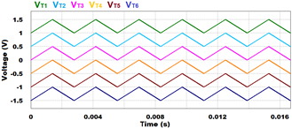
II: Phase Opposition Disposition (POD). Carriers above zero are 180° out of phase concerning carriers below zero, see Figure 4;
Figure 4. POD strategy modulating and carrier signals
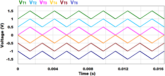
III: Alternative Phase Opposite Disposition (APOD). In this modulation strategy, all carriers are 180° out of phase concerning the adjacent carrier, see Figure 5;
Figure 5. APOD strategy modulating and carrier signals
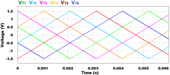
Figure 6. PSC strategy modulating and carrier signals
IV: Phase Shift Carrier (PSC). shifts the phase between the carrier signals to position the switching loop at a higher frequency than the switching frequency, see Figure 6 [8, 15]. Compared to Figures 3-5, in Figure 6 the time scale is shown at 0.006 s in order to better visualize the signals. The advantage of this modulation technique is that it reduces the harmonic content of the output voltage signal.
The PSC modulation technique is widely used in cascade multilevel inverters (CMLI) because it allows a high degree of freedom in the assignment of switching signals. Eq. (12) is used to determine the shifts of this modulation.
$\theta=\frac{360^{\circ}}{2 n}$ (12)
where, θ is the phase shift angle of the carrier signal and n is the number of signals per phase.
2.2 Three-phase induction motor
Table 1 shows the general specifications of the induction motor used as a load connected to the CMLI.
Table 1. Specifications of induction motor used
|
Parameter |
Value |
|
Nominal power |
1 hp |
|
Nominal voltage |
460 V |
|
Connection |
Y (star) |
|
Rated current in vacuum |
0.9 A |
|
Rated current at full load |
1.6 A |
|
Nominal speed |
1745 rpm |
|
Nominal efficiency |
85.5% |
|
NEMA design |
B |
|
Number of poles |
4 |
2.3 Topology
The CMLI topology generates a stepped output voltage waveform from multiple DC sources, trying to resemble a sine waveform at a desired amplitude and frequency. Its structure is based on cascading full-bridge inverters powered by isolated DC sources.
The objective is to simulate a sine waveform at a certain desired amplitude and frequency [11]. The CMLI topology has the following advantages over other multilevel topologies:
I: Reduces voltage unbalance problems, because it does not use capacitors in the DC bus [16].
II: Reduces the harmonic content in the output voltage signal [17].
III: Increased output voltage by increasing the number of cascaded full bridges, without affecting the voltage supported by power switches [18, 19].
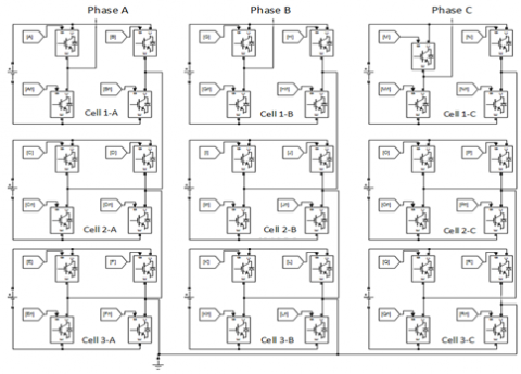
Figure 7 shows the schematic diagram of the three-phase CMLI of seven levels used in this study.
Figure 7. Schematic diagram of three-phase CMLI of seven levels
The comparative analysis of the variation of the parameters of the set: MLI+IM, considers parameters such as THD, WTHD, noise, vibrations, and temperature. The objective of this analysis is to evaluate the performance of the set MLI + IM using each one of the multicarrier PWM modulation techniques mentioned above.
The experimental tests were carried out under the specifications found in Table 2. To select the test time, the data presented in the study [20] were used.
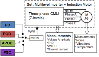
Figure 8 shows the experimental test methodology scheme. As a first step, the analysis modulation technique was selected. The second step is to obtain the measurements of the study parameters during the period of the experimental tests, using a fixed modulation index (m=0.9). This process is repeated for each modulation technique under study. Finally, an analysis and discussion of the results obtained experimentally were carried out.
Table 2. Specifications of experimental test parameters
|
Parameter |
Value |
|
Modulation index |
0.9 |
|
Switching frequency |
3.3 kHz |
|
Test duration |
60 min |
|
Number of measurements per test |
60 |
|
Ambient temperature |
29°C (±5%) |
|
Relative humidity |
32% (±1%) |
Figure 8. Scheme of the experimental testing methodology
Figure 9. The experimental platform of the set: multilevel inverter + induction motor
Figure 9 shows an image of the lateral view of the experimental platform of the three-phase cascade multilevel inverter of seven levels, and the induction motor used to perform the experimental tests.
Figure 10 shows the output voltage waveform of the three-phase CMLI (7-levels), using the PSC modulation technique with a modulation index of 0.9, which has a balanced behavior between its phases. The scale of the divisions shown in this figure are 5ms / div (x-axis) and 200 V / div (y-axis).
The comparative graphs below concentrate the results obtained experimentally, from Figure 11 to 17. However, it is important to note that these figures only show the measurements corresponding to phase A. Since the converter is a balanced system and the same values were obtained for phases B and C.
A comparative analysis of the behaviour of the previously selected parameters was carried out using the four modulation techniques. First, parameters related to the multilevel cascade converter, such as voltage amplitude, current amplitude, THD, and WTHD, were analyzed. Subsequently, the following parameters related to the three-phase induction motor were analyzed: noise, vibrations, and temperature.
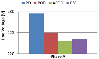
Figures 11 and 12 show the results obtained for voltage and nominal current, respectively. It can be observed that the PD modulation strategy transfers more power to the inverter output, this is because it obtained higher voltage and nominal current results. In contrast, the APOD technique is the one that transfers the lowest power.
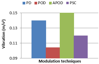
Continuing with the comparison of results, the following figures are presented for the induction motor. Figures 15 and 16 show the results related to the noise and vibration parameters, respectively. The APOD modulation technique obtained the highest values in both parameters, affecting its performance negatively. In contrast, the PSC and POD techniques showed a better performance obtaining better results in noise and vibration measurements, respectively.
Figure 10. The waveform of voltage at the output of a three-phase, CMLI seven levels. Phase A (red), phase B (blue) and phase C (yellow)
Figure 11. Value of the line voltage obtained for each modulation technique analyzed
Figure 12. The value of the line current obtained for each modulation technique analyzed
Figure 13. THD value obtained for each modulation technique analyzed
Figure 14. WTHD value obtained for each modulation technique analyzed
Figure 15. Noise parameter obtained for each modulation technique analyzed
Figure 16. The vibration parameter obtained for each modulation technique analyzed
Figure 17. The temperature obtained for each modulation technique analyzed
Finally, Figure 17 shows a comparison between the temperature values obtained. The POD modulation strategy showed less heating during the experimental test, reaching a temperature of approximately 46.5 °C. In contrast, the APOD technique had the highest temperature, with a value higher than 50°C.
The results obtained experimentally for each modulation technique are concentrated in Table 3. The modulation strategy that presented the best results concerning the other techniques was identified with a letter "X".
Table 3. Summary of experimental results
|
Study Parameter |
Modulation Technique |
|||
|
PD |
POD |
APOD |
PSC |
|
|
Line voltage |
X |
|
|
|
|
Line current |
X |
|
|
|
|
THD |
|
|
|
X |
|
WTHD |
|
|
|
X |
|
Noise |
|
|
|
X |
|
Vibration |
|
X |
|
|
|
Temperature |
|
X |
|
|
As can be seen in the table above, the comparison highlights the PSC modulation strategy, which obtained better results in the largest number of parameters (3 of 7) under study, related to the quality of the inverter output signal (THD and WTHD) and concerning the three-phase induction motor (noise). For this reason, Table 4 below shows the comparison of the results obtained in the different parameters using the PSC strategy, concerning the nominal values of the induction motor used as a load. The aforementioned with the purpose of observing quantitatively the variation between these results.
Table 4. Comparison of the modulation technique with better performance (PSC) vs nominal motor parameters
|
Parameter |
Values obtained with PSC |
Nominal Values |
Variation of values with PSC vs Nominal values |
|
Noise |
82.09dB |
82.06dB |
+ 0.04% |
|
Vibration |
0.12 m/s2 |
0.10 m/s2 |
+ 20% |
|
Temperature |
48.17°C |
49.3°C |
- 2.29% |
From the analysis of the results obtained in the application of the four variants of the multi-carrier PWM modulation technique to obtain the switching states of the power semiconductor devices for the three-phase cascade multilevel inverter of seven levels, the following conclusions were obtained:
I: The PSC modulation strategy had a better performance in 42.85% of the parameters (3 out of 7) studied. Obtaining the lowest values of THD, WTHD, and noise compared to the other three modulation techniques.
II: In contrast, the PD and POD techniques are found, both obtaining better performance in 28.57% of the analyzed parameters (2 of 7).
III: Finally, the APOD strategy presented the least favorable performance in all parameters evaluated.
The comparative results obtained provide the criteria for the selection of the most suitable modulation technique for the set: multilevel inverter + induction motor. When selecting the most suitable modulation technique for the set, the multilevel cascade inverter can provide a good quality voltage output waveform, which reduces ageing due to motor heating.
|
A APOD AT CMLI |
Amplitude Alternative Phase Opposition Disposition Amplitude of the triangular waveform Cascaded Multilevel Inverter |
|
DCMLI FC |
Diode Clamped Multilevel Inverter Frequency of the carrier signal |
|
FCMLI Fm IM m MLI NC Nl PD POD PSC PWM T THD VA VB VC WTHD |
Flying Capacitor Multilevel Inverter Frequency of the sine waveform Induction Motor Modulation index Multilevel Inverter Number of carriers Number of levels of the output signal Phase Disposition Phase Opposition Disposition Phase Shift Carrier Pulse Width Modulation Period Total Harmonic Distortion Voltage of phase A Voltage of phase B Voltage of phase C Weighted Total Harmonic Distortion |
[1] Mittal, N., Singh, B., Singh, S.P., Dixit, R., Kumar, D. (2012). Multilevel inverters: A literature survey on topologies and control strategies. 2nd International Conference on Power, Control and Embedded Systems, pp. 1-11. http://dx.doi.org/10.1109/ICPCES.2012.6508041
[2] Rodriguez, J., Jih-Sheng, L., Zheng, P.F. (2006). Multilevel inverters: A survey of topologies, controls, and applications. IEEE Transactions on Industrial Electronics, 49(4): 724-738. http://dx.doi.org/10.1109/TIE.2002.801052
[3] Barcenas, E. (2002). Análisis y desarrollo de un inversor multinivel. Centro Nacional de Investigación y Desarrollo Tecnológico, Cuernavaca, Morelos.
[4] Yahiaoui, A., Iffouzar, K., Himour, K., Ghedamsi, K. (2019). Comparison of different multilevel voltage source inverter topologies on induction motor energy quality. European Journal of Electrical Engineering, 21: 367-372. http://dx.doi.org/10.18280/ejee.210404
[5] Sahali, Y., Fellah, M.K. (2006). Application of the optimal minimization of the THD technique to the multilevel symmetrical inverters and study of its performance in comparison with the selective harmonic elimination technique. International Symposium on Power Electronics, Electrical Drives, Automation and Motions, SPEEDAM, Taormina, Italy, pp. 1342-1348. http://dx.doi.org/10.1109/SPEEDAM.2006.1649976
[6] Garibaldi, A.M. (2014). Relación entre el número de conmutaciones y la calidad de forma de onda de tensión en inversores multinivel asimétricos. Electrónica, Centro de Investigación y Desarrollo Tecnológico, Cuernavaca, Morelos.
[7] Hosseini, S.H., Sadigh, A.K., Barakati, S.M., Kangarlu, M.F. (2009). Comparison of SPWM technique and selective harmonic elimination using genetic algorithm. International Conference on Electrical and Electronics Engineering - ELECO 2009, pp. I-278-I-282. https://doi.org/10.1109/ELECO.2009.5355372
[8] Sánchez, C.A.S. (2008). Estrategia PWM implementada en un FPGA para aplicaciones en inversores multinivel. Electrónica, Centro Nacional de Investigación y Desarrollo Tecnológico, Cuernavaca, Morelos.
[9] Babaei, E., Hosseini, S.H. (2009). New cascaded multilevel inverter topology with minimum number of switches. Energy Conversion and Management, 50(11): 2761-2767. http://dx.doi.org/10.1016/j.enconman.2009.06.032
[10] Bharathi, C.R. (2019). Design of new asymmetrical cascaded multilevel inverter with reduced number of switches. European Journal of Electrical Engineering, 21(6): 547-552. http://dx.doi.org/10.18280/ejee.210609
[11] Franquelo, L.G., Rodriguez, J., Leon, J.I., Kouro, S., Portillo, R., Prats, M.A.M. (2008). The age of multilevel converters arrives. IEEE Industrial Electronics Magazine, 2(2): 28-39. http://dx.doi.org/10.1109/MIE.2008.923519
[12] Rashid, M.H. (2004). Electrónica de potencia: circuitos, dispositivos y aplicaciones. Pearson Educación, México.
[13] Malinowski, M., Gopakumar, K., Rodriguez, J., Perez, M.A. (2010). A survey on cascaded multilevel inverters. IEEE Transactions on Industrial Electronics, 57(7): 2197-2206. http://dx.doi.org/10.1109/TIE.2009.2030767
[14] Khoucha, F., Ales, A., Khoudiri, A., Marouani, K., Benbouzid, M.E.H., Kheloui. (2010). A 7-level single DC source cascaded H-bridge multilevel inverters control using hybrid modulation. The XIX International Conference on Electrical Machines - ICEM 2010, pp. 1-5. http://dx.doi.org/10.1109/ICELMACH.2010.5608179
[15] Agelidis, V.G., Balouktsis, A., Cossar, C., Balouktsis, I. (2005). Five-level selective harmonic elimination PWM strategies and multicarrier phase-shifted sinusoidal PWM: A comparison. IEEE 36th Power Electronics Specialists Conference, pp. 1685-1691. http://dx.doi.org/10.1109/PESC.2005.1581857
[16] Ramirez, J.P., Jimenez, J.A.B., Lopez, J.H.H., Ramos, R.F.U. (2018). Hybrid modulation strategy for asymmetrical cascade h-bridge multilevel inverters. IEEE Latin America Transactions, 16(6): 1623-1630. https://doi.org/10.1109/TLA.2018.8444158
[17] Schuwirth, A.A.B. (2003). Diseño y construcción de un inversor trifásico multinivel de cuatro etapas para compensación armónica y de reactivos,. Pontificia Universidad Católica de Chile, Santigo, Chile.
[18] Rehaoulia, A., Rehaoulia, H., Fnaiech, F. (2018). Output voltage quality analysis of three-phase multilevel inverters. Electrical Engineering, 100: 733-739. http://dx.doi.org/10.1007/s00202-017-0543-1
[19] Baimel, D., Rabinovici, R., Tapuchi, S., Baimel, N. (2015). Analysis of hybrid thirteen level cascaded H-bridge inverter operated under different PWM methods. 17th European Conference on Power Electronics and Applications (EPE'15 ECCE-Europe), pp. 1-10. http://dx.doi.org/10.1109/EPE.2015.7311766
[20] Association, N.E.M. (2016). NEMA MG1: Motors and Generators: NEMA. Mexico, México.