Abdelmalik Bendaikha* | Salah Saad | Abdelhak Abdou | Mabrouk Defdaf | Yahia Laamari
OPEN ACCESS
In order to reduce torque and flux fluctuations as well as harmonic currents distortion, two models were developed, the first is based on conventional DTC and the second is based on the SVM-DTC, controlling induction motor fed by a Five-level inverter. PI controller is employed for flux and torque control in order to obtain reference voltages Vd and Vq that will be used in the SVM algorithm.
The developed models were validated by simulation tests and the obtained results have showed the advantages of DTC-SVM control over conventional DTC in harmonic currents distortion, torque and flux fluctuations reductions.
space vector algorithm, switching frequency, harmonic distortion, stator flux, diode clamped inverter, reference voltages, PI controllers, torque fluctuations, duration of the commutations
The recent progress in electric motor control systems is mainly due to the increased demand for motors with high torques and speeds and the advances in semiconductor power components. These recent components can satisfy the above requirements and have also high switching frequency under very high voltages and currents.
The improvements in the field of micro informatics (powerful and fast microcontrollers) have allowed the synthesis of converters control algorithms and machine became more powerful and more robust [1-3].
Industrial variable speed drives applications require high performance, maximum reliability and minimum cost. The application of static converters is due to the development of controlled power semiconductors during on (conduction) and off (blocking) states such as MOSFETs, IGBTs, GTOs [4].
The use of a conventional two-level inverter in the field of high power applications is not appropriate, as it requires electronic components capable of withstanding high reverse voltage and currents of high intensity [5-6].
The direct torque control (DTC) was initially developed for asynchronous machines during 1986-1988 by TAKAHASHI and DEPENBROCK, [6-9]. This type of control considers the association of inverter and machine as a set where the vector control is established from the semiconductors switching states. Its main advantages are the speed and the dynamic torque fast response as well as low dependence on machine parameters. However, two major disadvantages arise. The first is the determination of the switching states based on information concerning the evolution trends of the flux and the torque resulting from the nonlinear elements of hysteresis type. The second is related to torque and flux fluctuations, as the duration of the commutations is variable. In order to overcome the severe computation time constraints and improve the performance of conventional DTC control, another technique is developed, imposing a constant modulation frequency [10].
In this work, direct vector-based torque control (DTC-SVM) applied to an induction motor fed by a Five-level NPC inverter is presented. This control is capable to improve the switching strategy of the inverter, resulting in a large number of voltage vectors to reduce flux and torque fluctuations and switching frequency [11-13]. The design of this control technique is proposed to improve the performance of the drive systems by PI controllers associated with vector modulation technique (SVM).
In this paper, two control algorithms (classical DTC and DTC-SVM) are developed in order to compare and show the advantages of the proposed technique over conventional DTC control strategy.
The obtained results are very encouraging demonstrating an important reduction in harmonic ratio (THD) when DTC-SVM technique is employed.
2.1 Induction motor modeling
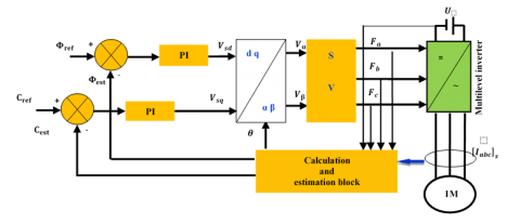
Principal, theoretical developments and modeling of DTC are well covered in the literature [9]. Figure 1 below shows the structure of the DTC-SVM for induction motor fed by a multilevel inverter. For both models, PI controllers of flux and torque were inserted in order to obtain the reference voltages Vd and Vq which will be used in the SVM algorithm [4].
Figure 1. Induction motor DTC-SVM structure
The motor stator voltage vector Vs can be expressed as follows [9]:
\({{\overline{V}}_{s}}\,=\,{{\overline{R}}_{s}}.{{\overline{I}}_{s}}+\frac{d{{\overline{\varphi }}_{s}}}{dt}\) (1)
Direct torque control is based on stator flux orientation. The expression of the stator flux in the reference frame according to motor stator is obtained by the following equation (2):
\({{\overline{\varphi }}_{s}}\,={{\overline{\varphi }}_{s0}}+\int\limits_{0}^{t}{\left( {{\overline{V}}_{s}}\,-{{\overline{R}}_{s}}.{{\overline{I}}_{s}} \right)dt}\) (2)
Neglecting the resistor voltage drop, the flux expression will become:
\({{\overline{\varphi }}_{s}}\left( t \right)\approx \,{{\overline{\varphi }}_{s}}\left( 0 \right)+\int\limits_{0}^{t}{{{\overline{V}}_{s}}.dt}\) (3)
The electromagnetic torque can be expressed as follows:
\({{C}_{e}}\,=p\frac{3}{2}\left( {{\varphi }_{\text{s }\!\!\alpha\!\!\text{ }}}{{I}_{\text{ }\!\!\beta\!\!\text{ }}}\text{-}{{\varphi }_{\text{s }\!\!\beta\!\!\text{ }}}{{I}_{\text{ }\!\!\alpha\!\!\text{ }}} \right)\) (4)
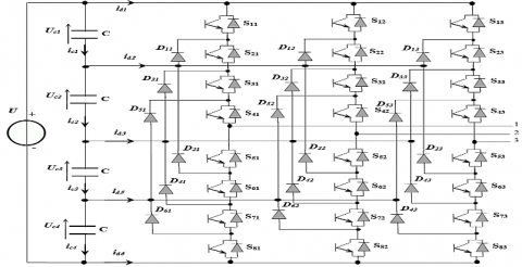
The diode clamped inverter is chosen because of its simplicity compared to other types of multilevel inverters, Figure 2 [4].
Figure 2. Structure of diode clamped Five-level inverter
Diode clamped five-level inverter has three symmetrical arms each consisting of eight bidirectional switches in series. These switches must not be ON or OFF simultaneously
in order to avoid the short circuit of the inverter dc source. Each switch consists of a bi-commendable semiconductor and a diode connected in anti-parallel. Six diodes in each arm to ensure the application of different voltage levels at the output of each arm. All arms are connected to a dc supply of electromotive force (4Uc), these four generators are equal. This inverter is a five-level because it delivers five voltage levels per arm (U/2, U/4, 0, -U/4, -U/2) [4].
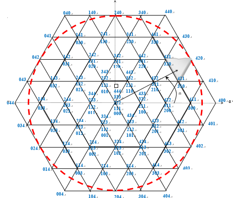
Five-level inverter space vector diagram with sectors and regions are presented in Figure 3 and Figure 4 respectively. These figures illustrate how five-level space vector algorithm is developed.
3.1 Switching functions
For each switch $S_{ij}(i=\overline{1-8},j=\overline{1-3})$, a switching function is defined as follows [4]:
\( F_{ij}= \left\{\begin{array}{rl} 1 & \text{if } S_{ij} is ON\\ 0 & \text{if } s_{ij} is OFF \end{array} \right. \) (5)
The switches of the lower-half arm are complementary with the switches of upper half-arm
\(F_{ij}=1-{F}_{(i-4)j},i=\overline{5-8}; j=\overline{1-4}\) (6)
Figure 3. Inverter space vector diagram
Table 1. Switching state of one arm of five-level inverter [4]
|
State |
S1x |
S2x |
S3x |
S4x |
S5x |
S6x |
S7x |
S8x |
V0x |
|
4 |
1 |
1 |
1 |
1 |
0 |
0 |
0 |
0 |
U /2 |
|
3 |
0 |
1 |
1 |
1 |
1 |
0 |
0 |
0 |
U /4 |
|
2 |
0 |
0 |
1 |
1 |
1 |
1 |
0 |
0 |
0 |
|
1 |
0 |
0 |
0 |
1 |
1 |
1 |
1 |
0 |
-U /4 |
|
0 |
0 |
0 |
0 |
0 |
1 |
1 |
1 |
1 |
-U /2 |
Figure 4. Sectors and regions of space vector diagram
The motor parameters used in simulation are presented in Table 2.
Table 1. Motors parameters Asynchronous motor technical parameters
|
Parameters |
Values |
|
- Motor power - Nominal frequency - pole pair Number - Supply voltage - Nominal current - Nominal rotational speed - Stator resistance - Rotor resistance - Stator inductance - Rotor inductance - Mutual inductance - moment of inertia - Friction coefficient |
Pn= 1.1Kw F = 50Hz P=2 un=220v In = 13A nn = 1725tr/min Rs = 6.75 Ω Rr = 6.21 Ω Ls = 0.5192H Lr = 0.5192H Msr = 0.5H J = 0.01240 Kgm2 f = 0.002 Kg m2/s |
In order to validate the conventional DTC and SVM-DTC
4.1 Conventional DTC applied to asynchronous machine fed by Five -level inverter
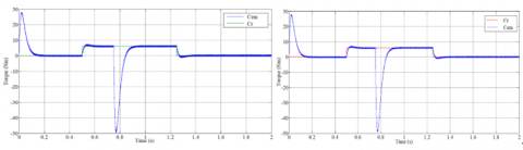
Developed algorithms with PI controllers for an induction motor supplied by five-level inverter are presented in Figures (5) to (15) Figure (5) illustrates the phase to neutral voltage. The torque curve presented in Figure (6), for conventional DTC having a transient state section from 0 to 0.16s, no load operation section from 0.16-0.5s, a load (6 N.m) operation section applied at 0.5s with a time response less than 0.11s and section for rotation reversing direction test with loaded motor at 0.75s and load elimination at 1.25s is presented to show motor speed response. SVM-DTC curve also has a transient state section from 0 to 0.14s, no load (0.00 N.m) operation section from 0.14-0.5s, a section of loaded (6 N.m) motor operation applied at 0.5s with a time response is less than 0.07s, and a section for rotation reversing direction test at 0.75s and load elimination at 1.25.
It can be noticed in Figure (7) an appreciable reduction of torque ripple as illustrated in zoomed torque response figure, the torque ripples in DTC-SVM are much less compared to conventional DTC torque ripples.
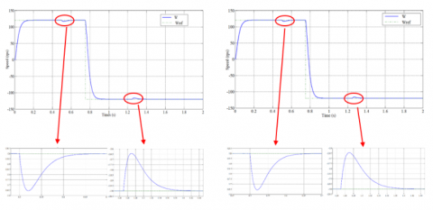
Figure (8) illustrates the speed responses for both conventional DTC and SVM-DTC techniques according to speed reference step of 120 rad/s with motor loaded at 0.5s and unloaded at 1.25s.
A speed reversal from positive to negative value (120 rad/s; –120 rad/s) is conducted at 0.75s. In Figure (9), the zoomed speed response shows that both techniques have similar speed response and load rejection when the same PI speed controller is used.
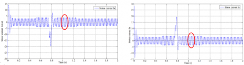
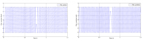
Figures (10) to (12) present respectively the stator phase current, its zoom (zoomed for comparison) and frequency spectrum. In addition, the results have confirmed that SVM-DTC has lower THD value (0.86 %) compared to the value of conventional DTC (2.22 %). The flux angle is shown in Figure (13).
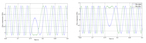
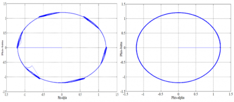
In order to indicate the reversing direction of rotation, Figure (14) and (15) show the stator flux components and its trajectory where the magnitude is following its reference (1Wb).
All simulations tests results are presented below for both techniques for comparison.
4.2 SVM-DTC to asynchronous machine fed by Five-level inverter
Figure 5. Inverter output phase to neutral voltage Va
Figure 6. Induction motor torque at transient and steady state
Figure 7. Zoomed torque response for time interval 1sec to 1.1 sec
Figure 8. Induction motor speed with sense reversing direction at 0.75s Figure 9. Zoom of speed response
Figure 10. Steady states stator current Ia
Figure 11. Zoom of current (Ia) response time interval 1to1.1 sec
Figure 12. Stator current frequency spectrum
Figure 13. Rotation reversing direction: stator flux position
Figure 14. Rotation reversing direction: Stator flux components (Wb)
Figure 15. Stator flux trajectory (Wb)
In this paper a comparative study of two techniques, one based on SVM-DTC and the other is based on conventional DTC controlling an induction motor fed by five-level inverter is presented and discussed. The obtained results have showed the advantages of SVM-DTC over conventional DTC such as reduced THD value of stator current, torque ripples and flux fluctuations with better stator voltage waveform.
The speed disturbance rejection is quick and tracks its reference with high static performance. Moreover, SVM-DTC has better dynamic control under different operation conditions. Comparing the results of the present study to the results of the literature, it can be noticed that current THD value is well below the obtained values of [1, 13].
|
DTC |
Direct torque control |
|
DTC-SVM |
Direct torque control space victor modulation |
|
SVPWM |
space vector Pulse Width Modulation |
|
U Fij Vs Iα, Iβ W Wref Ce Φs Rs p |
Direct voltage source switching function Stator voltage vector Stator voltages αβ components Induction motor speed Electromagnetic Speed reference Induction motor torque Stator flux Stator resistance Number of pole pairs |
[1] Sekhar OC, Sekhar KC. (2012). A novel five-level inverter topology for DTC induction motor drive. IEEE International Conference on Advanced Communication Control and Computing Technologies (ICACCCT), pp. 392-396. https://doi.org/10.1109/ICACCCT.2012.6320809
[2] Lucia S, Navarro D, Lucia O, Zometa P, Findeisen R. (2018). Optimized FPGA Implementation of model predictive control for embedded systems using high level synthesis Tool 14(1): 137-145. https://doi.org/10.1109/TII.2017.2719940
[3] Kouro S, Bernal R, Miranda H, Rodrıguez J, Pontt J. (2006). Direct torque control with reduced switching losses for asymmetric multilevel inverter fed induction motor drives. Conference Record of the 2006 IEEE Industry Applications Conference Forty-First IAS Annual Meeting 35(4): 2441-2446. http://doi.org/10.1109/IAS.2006.256882
[4] Bendaikha A, Saad S. (2017). Comparative study of five-level and seven-level inverter controlled by space vector pulse width modulation. International Journal of Power Electronics and Drive System (IJPEDS) 8(2): 755-766. http://doi.org/10.11591/ijpeds.v8.i2.pp755-766
[5] Application Note 9019, FAIRCHILD, Semiconductor, Motor Drive System Using SVM Inverter, October, 2001.
[6] Takahashi I, Ohmori Y. (1989). High performance direct torque control of an induction motor. IEEE Transactions on Industry Applications IA-25(2): 257-264. http://doi.org/10.1109/28.25540
[7] Takahashi I, Noguchi T. (1986). A new QuickResponse and high-efficiency control of an induction motor. IEEE Transactions on Industry Applications IA-22(5): 820-827. http://doi.org/10.1109/TIA.1986.4504799
[8] Kumar A, Fernandes BG, Chatterjee K. (2005). DTC of open-end winding induction motor drive with complete elimination of common mode voltage. 31st Annual Conference of IEEE Industrial Electronics Society1 504-1509. http://doi.org/10.1109/IECON.2005.1569127
[9] Berrabah F, Saad S, Chebabhi A. (2016). SVM technique based on DTC sensorless control optimized by ANN applied to a double stator asynchronous machine fed by three-level six-phase inverter. The Mediterranean Journal of Measurement and Control 12(2): 71-579. http://doi.org/10.18280/ama_c.720405
[10] Zhang Z, Zhao Y, Qiao W, Qu LY. (2013). A space-vector modulated sensorless direct-torque control for direct-drive PMSG wind turbines. IEEE Transactions on Industry Applications 50(4): 2331-2341. http://doi.org/10.1109/TIA.2013.2296618
[11] Abu-Rub H, Stando D, Kazmierkowski MP. (2013). Simple speed sensorless DTC-SVM scheme for induction motor drives. The Journal of Polish Academy of Sciences 62(2): 301-307. http://doi.org/10.2478/bpasts-2013-0028
[12] Berrabah F, Chebabhi A, Zeghlache S, Saad S. (2017). Direct torque control of induction motor fed by three-level inverter using fuzzy logic. Advances in Modelling and Analysis C 72(4): 248-265. http://doi.org/10.18280/ama_c.720404
[13] Sekhar OC, Sekhar KC. (2013). A five-level SVM inverter for an induction motor with direct torque controller. Journal of Electrical Engineering(.jee) 13(4): 1-9.