Abdesslam Lokriti | Issam Salhi* | Said Doubabi
OPEN ACCESS
The purpose of this paper is to prove that Induction Motor (IM) torque drive based on Direct Rotor Field Oriented Control (DRFOC) could be achieved using no currents controllers and no PWM block. In fact, we propose, after an inverse Park rotation applied on direct and quadratic stator flux components, to control both stator flux components, real and imaginary, through two hysteresis controllers. Therefore, a switching table is established. It’s independent from sector determination, does not introduce zero voltage vectors and with reduced size compared to Takahashi’s switching table. Thus, a new approach to realize DRFOC is provided. The proposed DRFOC is validated by practical implementation on a DSPace 1104 board, for a 1.5 kW IM.
induction motor, direct rotor field oriented control, flux distortion, reduced switching table
The Induction Motors (IM) vector control (VC) is based on dynamic model. Thus, not only magnitude and frequency but also instantaneous positions of the different electromagnetic quantities are controlled [1]. This qualifies VC to be used in IM high performances applications [2-4]. Actually, there are many techniques to achieve VC, namely: feedback linearization [5-6], passivity based control [7], Field Oriented Control (FOC) [8], Direct Torque Control (DTC) [9-10] and DTC-Pulse Width Modulation control (DTC-PWM) [11-14].
Practically, Rotor FOC (RFOC) and DTC remain the most widely used VC techniques in high performances IMs torque drive [1]. Thereby, several comparisons between DTC and RFOC strategies have been emerged [15-21]. Indeed, some researchers have compared the DTC performances with those of the Indirect RFOC (IRFOC) when IMs are fed by Static Voltage Inverter (SVI) [15]. They concluded that, contrary to the IRFOC, the DTC does not need to determinate the rotor instantaneous pulsation and does not depend on rotor resistance. Moreover, several researchers consider that the RFOC must always be performed through current controllers. This is the reason why the majority of them note that the RFOC always needs: (i) inner currents loops; (ii) presents slow torque dynamic and (iii) introduces a Pulse Width Modulation (PWM) block [1, 22].
From our point of view, these comparisons are not rigorous:
In this paper, DRFOC through stator flux hysteresis controllers, instead of current feedback, is performed to achieve torque reference IM dynamic improvement using: (i) a linear torque controller, (ii) Park inverse rotation, (iii) a reduced switching table, (iv) two hysteresis controllers and (v) a rotor flux angle and stator flux estimator. The proposed DRFOC control is argued experimentally through practical tests implemented on a DSPace 1104 board for various IM torque references for a 1.5kW IM. The performance is evaluated in terms of torque dynamic and ripple, flux and current distortion.
In the synchronous rotating reference frame (d, q), the IM electromagnetic torque could be given by one of the following equalities [1]:
${{T}_{e}}=p\frac{{{L}_{m}}}{{{L}_{r}}}{{\phi }_{r}}{{i}_{s}}\sin ({{\bar{i}}_{s}},{{\bar{\phi }}_{r}})=p\frac{{{L}_{m}}}{{{L}_{r}}}({{\phi }_{rd}}{{i}_{sq}}-{{\phi }_{rq}}{{i}_{sd}})$ (1)
${{T}_{e}}=p\frac{{{L}_{m}}}{\sigma {{L}_{r}}{{L}_{s}}}{{\phi }_{r}}{{\phi }_{s}}\sin ({{\bar{\phi }}_{s}},{{\bar{\phi }}_{r}})=p\frac{{{L}_{m}}}{\sigma {{L}_{r}}{{L}_{s}}}({{\phi }_{dr}}{{\phi }_{sq}}-{{\phi }_{dq}}{{\phi }_{sd}})$ (2)
According to the RFOC principal, when forcing φrd= φr* and φrq= 0, one can choose to control both rotor flux and torque either through stator currents or by stator flux. This means to consider respectively one of the following equations [1, 2]:
if stator currents are chosen:
$i_{sd}^{*}=\frac{1}{{{L}_{m}}}(1+s{{T}_{r}})\phi _{r}^{*}$, $i_{sq}^{*}=\frac{{{L}_{r}}}{p{{L}_{m}}}\frac{T_{e}^{*}}{\phi _{r}^{*}}$ (3)
If stator flux are chosen:
$\phi _{sd}^{*}=\frac{{{L}_{s}}}{{{L}_{m}}}(1+s\sigma {{T}_{r}})\phi _{r}^{*}$,$\phi _{sq}^{*}=\frac{\sigma {{L}_{s}}{{L}_{r}}}{p{{L}_{m}}}\frac{T_{e}^{*}}{\phi _{r}^{*}}$ (4)
where (s) represent Laplace variable.
Based on expressions (3) and (4), the time constant between rotor and stator flux direct components is (σTr); while a time constant equal to (Tr) links the rotor flux direct component to the stator current’s one. This is why, when the stator flux is used to control both IM rotor flux and torque, their dynamics are very rapid compared to the case when stator current inner loops are used.
Remark: φrd= φr* is usually replaced by:
${{\phi }_{sd}}^{*}=\frac{{{L}_{s}}}{{{L}_{m}}}\phi _{r}^{*}$ and $i_{sd}^{*}=\frac{1}{{{L}_{m}}}\phi _{r}^{*}$ (5)
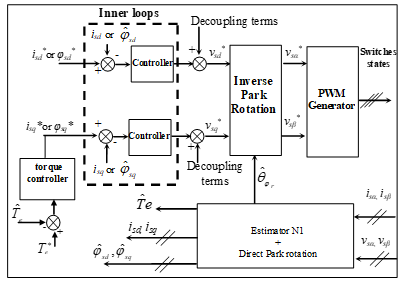
In this case, DRFOC diagram for IM supplied by SVI could be presented as shown in figure 1.
Figure 1. Voltage inverter based DRFOC drive
The estimator N1 estimates the stator flux components in the stationary reference frame (α, β)s [1]:
${{\hat{\phi }}_{s\alpha }}=\text{ }\int{({{v}_{s\alpha }}-}{{R}_{s}}\text{ }{{i}_{s\alpha }}\text{)}dt,\text{ }{{\hat{\phi }}_{s\beta }}=\text{ }\int{({{v}_{s\beta }}-}{{R}_{s}}\text{ }{{i}_{s\beta }})dt$ (6)
Then, the rotor flux components are estimated as given below:
${{\hat{\phi }}_{r\alpha }}=\frac{{{L}_{r}}}{{{L}_{m}}}\text{ (}{{\hat{\phi }}_{s\alpha }}-\sigma {{L}_{s}}\text{ }{{i}_{s\alpha }}\text{), }{{\hat{\phi }}_{r\beta }}=\frac{{{L}_{r}}}{{{L}_{m}}}\text{ (}{{\hat{\phi }}_{s\beta }}-\sigma {{L}_{s}}\text{ }{{i}_{s\beta }}\text{)}$ (7)
The rotor flux position with respect to the stator reference frame and the electromagnetic torque are estimated respectively by:
${{\hat{\theta }}_{{{\phi }_{r}}}}=arctg(\frac{{{{\hat{\phi }}}_{r\beta }}}{{{{\hat{\phi }}}_{r\alpha }}})$ (8)
${{\hat{T}}_{e}}=p\frac{{{L}_{m}}}{{{L}_{r}}}({{\hat{\phi }}_{r\alpha }}{{i}_{s\beta }}-{{\hat{\phi }}_{r\beta }}{{i}_{s\alpha }})=p\frac{{{L}_{m}}}{\sigma {{L}_{r}}{{L}_{s}}}({{\hat{\phi }}_{r\alpha }}{{\hat{\phi }}_{s\beta }}-{{\hat{\phi }}_{r\beta }}{{\hat{\phi }}_{s\alpha }})$ (9)
Actually, voltage inverter based DRFOC scheme can be significantly simplified if stator flux control is achieved in the stator reference frame (α, β)s. In fact, in this frame the stator resistance is often neglected. Also, the direct Park rotation could be removed because there is no need to compute direct and quadratic stator flux components. Moreover, in this frame, even the PWM generator block may be removed, as discussed below.
3.1 Controlling stator flux in (α, β)s reference frame and elimination of direct Park rotation
In the (α, β)s reference frame, when the stator resistance is neglected, the expression that links the stator flux and voltage become:
${{v}_{s\alpha }}=\frac{d{{\phi }_{s\alpha }}}{dt}$,${{v}_{s\beta }}=\frac{d{{\phi }_{s\beta }}}{dt}$ (10)
In order to achieve the stator flux control in the (α, β)s reference frame, we use the so-called discrete derivative controllers [1],which ensures the following computations :
$\left\{ \begin{align} & {{v}_{s{{\alpha }_{k}}}}^{*}=\frac{{{(\Delta {{\phi }_{s\alpha }}_{_{k}})}^{*}}}{{{T}_{s}}}\text{ with:}{{(\Delta {{\phi }_{s\alpha }}_{_{k}})}^{*}}={{\phi }_{s\alpha }}{{_{_{k}}}^{*}}-{{{\hat{\phi }}}_{s\alpha }}_{_{k-1}} \\ & {{v}_{s{{\beta }_{k}}}}^{*}=\frac{{{(\Delta {{\phi }_{s\beta }}_{_{k}})}^{*}}}{{{T}_{s}}}\text{with:}{{(\Delta {{\phi }_{s\beta }}_{_{k}})}^{*}}={{\phi }_{s\beta }}{{_{_{k}}}^{*}}-{{{\hat{\phi }}}_{s\beta }}_{_{k-1}} \\ \end{align} \right.$ (11)
where ${{{\hat{\phi }}}_{s\alpha }}_{_{k-1}}$ and ${{{\hat{\phi }}}_{s\beta }}_{_{k-1}}$ represent the estimated stator flux components at the time instant tk-1, and Ts is the used sampling time. Thus, the DRFOC diagram becomes:
Figure 2. DRFOC drive diagram in (α, β)s
We note that this technique is very close to the DTC-SVM. The only difference is the angle used for reverse Park rotation. The DTC-SVM uses the angle of the stator flux vector whereas here it is rather the rotor flux one.
3.2 Elimination of the PWM generator
Actually, in the stationary reference frame (α, β)s, it is possible to achieve stator flux control through hysteresis controllers as detailed in [28]. The diagram of the DRFOC could be illustrated as given by figure 3, where, Table I presents the switching table and the two chosen controllers are shown respectively in figures 4 and 5.
In fact, according to the effect brought by each voltage vector to the stator flux components in the (α, β)s reference frame, a switching table I is summarized as follow [28]:
Figure 3. DRFOC drive diagram in (α, β)s using a switching table
Figure 4. DRFOC drive diagram in (α, β)s using a switching table
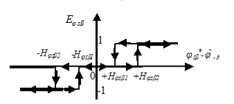
Figure 5. φsα hysteresis controller
Table 1. Switching table I
|
Eφsα |
1 |
-1 |
||||
|
Eφsβ |
1 |
0 |
-1 |
1 |
0 |
-1 |
|
$\bar{v}_s$ |
$\bar{v}_{s_2}$ |
$\bar{v}_{s_1}$ |
$\bar{v}_{s_6}$ |
$\bar{v}_{s_3}$ |
$\bar{v}_{s_4}$ |
$\bar{v}_{s_5}$ |
Eφsα =1 (Eφsβ=1) means that φsα (φsβ) should increase, Eφsα =-1 (Eφsβ=-1 ) means that φsα (φsβ) should decrease, and Eφsβ =0 means that φsβ should be kept unchanged. While Hφsα and Hφsβ represent respectively the half of the desired φsα and φsβ hysteresis bounds.
From figure 3, it’s clear that the DRFOC diagram, could be achieved by controlling the stator flux components expressed in the (α, β)s reference frame using two hysteresis controllers and a simple switching table (only six rules).
In order to validate the proposed DRFOC (figure 3), in terms of torque dynamics and both flux and stator current distortions, practical tests with various torque references were carried out. The realized experimental test rig is shown in figure 6. Indeed, it consists of:
After building the proposed DRFOC real-time Simulink-blocks, the C code is automatically generated by the Real-Time Workshop in conjunction with the DSPace’s Real-Time Interface. The Real-Time Application is downloaded and executed in the DSPace’s global memory (32 MB, SDRAM). To monitor and save all the experiment data, we use the ControlDesk which is a DSPace’s experiment software.
Figure 6. The experimental platform
Table 2. The IM parameters values
|
p |
2 |
P |
1.5 kW |
|
Rs |
4.75 Ω |
Isn |
4.2 A |
|
Rr |
1.2 Ω |
Vsn |
380 V |
|
Ls |
0.4 H |
Ten |
10 N.m |
|
Lr |
0.072 H |
ωn |
175 rad/s |
|
Lm |
0.163 H |
f=fIM+fload |
25 ×10-4 Kg.m2/sec |
|
J=JIM +Jload |
0.025 Kg.m2 |
Ten |
10 N.m |
In order to limit torque and stator flux ripples within ±2.5% of their nominal values, the synthesis of DRFOC controller has been done as detailed in [28]. The adopted controllers’ parameters are given as follow:
$Hφ_{sα}=Hφsβ1=1.38×10^{-4}Wb$ (12)
$Hφ_{sβ2}=1.5×10^{-2}Wb$ (13)
${{k}_{p}}=\text{0}\text{.12}$ (14)
${{k}_{i}}=4.44$ (15)
The torque reference sequence lasts 35 (sec): Te * = [8, 5, 2, -6, -2, 6] N.m (figure 7). It is clear that this sequence covers different operating torque points (large steps, positive, negative, small and medium torque values). After a first implementation, we have obtained a computation time Tc = 50 (μsec). So we have chosen to execute the control with a sampling time Ts = 60 (μsec). The obtained experimental results are presented in the following figures:
Figure 7. Estimated (Te est), reference (Te ref) and filtered (Te estf) torques
Figure 8. Stator flux vector locus
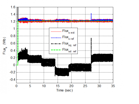
Figure 9. Stator flux: d-axis component (Fluxsd ref), q-axis component (Fluxs qref), reference magnitude (Fluxs ref) and estimated magnitude (Fluxs est)
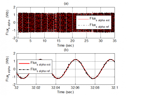
Figure 10. Stator flux α-axis component: (a) reference and estimated, (b) zoomed figure
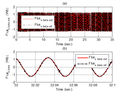
Figure 11. Stator flux β-axis component: (a) Reference and estimated, (b) zoomed figure
Figure 12. Stator current (a) measured, (b) zoomed figure
From Figure 7, we clearly see that the filtered estimated torque (dashed line) does not present any error with the use of the proposed DRFOC including a PI torque controller. Because the used sampling time is not small enough, we note that the torque ripple goes beyond the set hysteresis bounds (±0.25 N.m). Further, we note that the use of hysteresis stator flux controllers has improved the DRFOC torque dynamic that has become comparable to that of the classical DTC. The figure 8 shows that the flux vector locus presents few distortions, few ripples and closer circle shape.
From Figure 9, it’s clear that the estimated stator flux magnitude follows the desired magnitude reference and presents few ripples. For the same raison as for the torque, the magnitude flux ripples go beyond the set limits (±0.03 Wb). Less distortion could be achieved if less sampling time could have been used. The same figure shows also that the stator flux reference q-component follows exactly the torque shape, while, the d-component remains constant.
Figures 10 and 11 present the stator flux components waveforms in the stator reference frame. Indeed, Figures 10(b) and 11(b) show that the estimated values of these two components follows exactly their references and present almost-perfect sinusoidal forms. Thereby, even the stator current shape presents a sinusoidal form, as shown in Figure 12.
This paper has presented a novel approach to achieve DRFOC. In fact, from the possibility of realizing the DRFOC through stator flux inner loops performed in the stationary reference frame, we have confirmed theoretically and practically that this control can be achieved using: i) a linear torque controller, ii) Park inverse rotation, iii) a reduced switching table, iv) two hysteresis controller and v) a rotor flux angle and stator flux components estimator. In this case, DRFOC achieves better torque dynamic. Our practical realization was performed on a 1.5 kW IM torque drives.
The proposed control design has improved the torque dynamics and proved that the DRFOC could be achieved without using any current inner loop and no PWM bloc.
In this paper we have shown that the DRFOC could achieve the DTC dynamics. As a perspective, comparison with classical DRFOC and classical DTC, in terms of dynamic and steady state performance, might be investigated. Further, a comparison of THD/Torque ripple performance should be realized.
|
vs, is |
Stator voltage and current. |
|
φs, φr |
Stator and rotor flux. |
|
θφs ,θφr |
Positions of stator and rotor flux in the stator frame. |
|
ω |
Mechanical rotor speed. |
|
2.p |
number of poles. |
|
Te |
Electromagnetic torque. |
|
Tr |
Rotor time constant. |
|
Rs |
Stator resistance. |
|
Ls ,Lr ,Lm |
Stator, rotor and mutual inductances. |
|
σ |
Total leakage factor. |
|
H(.) |
Denotes hysteresis bound for a chosen variable. |
|
E(.) |
Denotes logical decision for a chosen variable. |
|
(.)* |
Denotes a reference value. |
|
(^) |
Denotes an estimated value. |
|
(.)α,β |
Denotes α and β axis-components for a chosen variable. |
|
(.)d,q |
Denotes d and q axis-components for a chosen variable. |
[1] Roubache T, Chaouch S, Natï-Sadï MS. (2018). Comparative study between luenberger observer and extended kalman filter for fault-tolerant control of induction motor drive. AMSE IIETA Advances in Modelling and Analysis C 73(2): 29-36. https://doi.org/10.18280/ama_c.730201
[2] Lokriti A, Salhi I, Doubabi S, Zidani Y. (2013). Induction motor speed drive improvement using fuzzy IP-self-tuning controller A real time implementation. ISA Transactions 52(3): 406-417. https://doi.org/10.1016/j.isatra.2012.11.002
[3] Belhamdi S, Amar G. (2017) Direct field-oriented control using fuzzy logic type-2 for induction motor with broken rotor bars. AMSE JOURNALS-AMSE IIETA Publication 72(4): 203-212. https://doi.org/10.18280/ama_c.720401
[4] Lallouani H, Belhamdi S. (2018). Speed control of doubly star induction motor (DSIM) using direct field-oriented control (DFOC) based on fuzzy logic controller (FLC). AMSE IIETA Advances in Modelling and Analysis C 73(4): 128-136. https://doi.org/10.18280/ama_c.730402
[5] Gastaldini CC, Vieira RP, Azzolin RZ, Grndling HA. (2013). Feedback linearization control with sliding mode speed observer for three-phase induction machines. 2013 Brazilian Power Electronics Conference, pp. 345-349. https://doi.org/10.1109/COBEP.2013.6785138
[6] Sira-Ramirez H, Gonzalez-Montanez F, Cortes-Romero JA, Luviano-Juarez A. (2013). A robust linear field-oriented voltage control for the induction motor: experimental results. IEEE Transactions on Industrial Electronics 60(8): 3025-3033. https://doi.org/10.1109/TIE.2012.2201430
[7] Gokdere LU, Simaan MA, Brice CW. (2001). Passivity-based control of saturated induction motors. IEEE Transactions on Industrial Electronics 48(4): 870-872. https://doi.org/10.1109/41.937423
[8] Amezquita-Brooks L, Liceaga-Castro J, Liceaga-Castro E. (2014). Speed and position controllers using indirect field-oriented control: A classical control approach. IEEE Transactions on Industrial Electronics 60(4): 1928-1943. https://doi.org/10.1109/TIE.2013.2262750
[9] Belhamdi S, Goléa A. (2015). Direct torque control for induction motor with broken bars using fuzzy logic type-2. AMSE Journals Series: Modelling C 70(1): 15-28.
[10] Sorchini Z, Krein PT. (2006). Formal derivation of direct torque control for induction machines. IEEE Transactions on Power Electronics 21(5): 1428-1436. https://doi.org/10.1109/TPEL.2006.882086
[11] Barika SK, Jaladi KK. (2016). Five-phase induction motor DTC-SVM scheme with PI controller and ANN controller. Procedia Technology 25: 816-823. https://doi.org/10.1016/j.protcy.2016.08.184
[12] Ammar A, Bourek A, Benakcha A. (2017). Nonlinear SVM-DTC for induction motor drive using input-output feedback linearization and high order sliding mode control. ISA Transactions 67: 428-442. https://doi.org/10.1016/j.isatra.2017.01.010
[13] Costa BLG, Graciola CL, Angélico BA, Goedtel A, Castoldi MF. (2018). Metaheuristics optimization applied to PI controllers tuning of a DTC-SVM drive for three-phase induction motors. Applied Soft Computing 62: 776-788. https://doi.org/10.1016/j.asoc.2017.09.007
[14] Ammar A, Benakcha A, Bourek A. (2017). Closed loop torque SVM-DTC based on robust super twisting speed controller for induction motor drive with efficiency optimization. International Journal of Hydrogen Energy 42(28): 17940-17952. https://doi.org/10.1016/j.ijhydene.2017.04.034
[15] Rezgui SE, Mehdi A, Legrioui S, Meddouce H. (2013). IRFOC vs DTC performance comparison analysis. 2013 3rd International Conference on Electric Power and Energy Conversion Systems. https://doi.org/10.1109/EPECS.2013.6713066
[16] Niu F, Wang K, Li B, Strangas EG. (2016). Comparative evaluation of direct torque control strategies for permanent magnet synchronous machines. IEEE Transactions on Power Electronics 31(2): 2438-2445. https://doi.org/10.1109/TPEL.2015.2421321
[17] Patil UV, Suryawanshi HM, Renge MM. (2012). Performance comparison of DTC and FOC induction motor drive in five level diode clamped inverter. IEEE-International Conference on Advances in Engineering, Science and Management (ICAESM -2012), pp. 227-230.
[18] Korkmaz F, Topaloglu I, Cakir MF, Gurbuz R. (2013). Comparative performance evaluation of FOC and DTC controlled PMSM drives. 4th International Conference on Power Engineering, Energy and Electrical Drives, 705-708. https://doi.org/10.1109/PowerEng.2013.6635696
[19] ElOuanjli N, Derouich A, El-Ghzizal A, Chebabhi A, Taoussi M. (2018). A comparative study between FOC and DTC control of the Doubly Fed Induction Motor (DFIM). 2017 International Conference on Electrical and Information Technologies (ICEIT). https://doi.org/10.1109/EITech.2017.8255302
[20] Struharňanský Ľ, Vittek J, Makyš P, Ilončiak J. (2017). Vector control techniques for traction drive with induction machines–comparison. Procedia Engineering 192: 851-856. https://doi.org/10.1016/j.proeng.2017.06.147
[21] Liu CA, Luo Y. (2017). Overview of advanced control strategies for electric machines. Chinese Journal of Electrical Engineering 3(2): 53-61. https://doi.org/10.23919/CJEE.2017.8048412
[22] Sudheer H, Kodad SF, Sarvesh BC. (2018). Improvements in direct torque control of induction motor for wide range of speed operation using fuzzy logic. Journal of Electrical Systems and Information Technology 5(3): 813-828. https://doi.org/10.1016/j.jesit.2016.12.015
[23] Fahassa C, Sayouti Y, Akherraz M. (2015). Improvement of the induction motor drive's indirect field oriented control performance by substituting its speed and current controllers with fuzzy logic components. 2015 3rd International Renewable and Sustainable Energy Conference (IRSEC). https://doi.org/10.1016/j.asoc.2017.09.00710.1109/IRSEC.2015.7454928
[24] Panchade VM, Chile RH, Patre BM. (2013). A survey on sliding mode control strategies for induction motors. Annual Reviews in Control 37(2): 289-307. https://doi.org/10.1016/j.arcontrol.2013.09.008
[25] Kaimierkowski MP, Dzieniakowski MA, Sulkowski W. (1991). Novel space vector based current controllers for pwm-inverters. IEEE Transaction on Power Electronics 6(1): 158-166. https://doi.org/10.1109/63.65014
[26] Kazmierkowski MP, Krishnan R, Blaabjerg F. (2002). Control in power electronics: Selected problems.
[27] Zhang Z, Tang R, Bai B, Xie D. (2010). Novel direct torque control based on space vector modulation with adaptive stator flux observer for induction motors. IEEE Transactions. on Magnetics 46(8): 3133-3136. https://doi.org/10.1109/TMAG.2010.2051142
[28] Lokriti A, Salhi I, Doubabi S. (2015). IM direct torque control with no flux distortion and no static torque error. ISA Transactions 59: 256-267. https://doi.org/10.1016/j.isatra.2015.08.014