Bhanuprasad Nuthalapati* | Umesh Kumar Sinha
OPEN ACCESS
Faults occurred in power system are common, all these faults are detected by protective devices but faults like Downed or Broken power line Fault not touching the ground, these faults not having enough faults current to operate fault detection devices in Over Head power distribution. Till now there is no protecting devices are identified this type of fault and location of this fault. As of now identifying by only by visual sighting. The proposed solution for finding Fault location Downed or Broken power line Fault not touching the ground.
power line communication (PLC), PLG (power line guardian), high impedance faults (HIF’s), fault current
In Power Transmission and distribution system line faults are common issues. Finding Fault and fault location is a critical issue for both Transmission and distribution system. An efficient fault protection and fault location scheme required to protects the equipment as well as public from hazardous over voltages. Downed conductors or broken power lines not touch the ground are of major concern to electric utilities because they may result in public hazard. Finding fault location of down power lines not touching ground is big problem because finding this type of fault is big concern in power system.
Downed conductors may not contact a conductive object and, therefore, have good probability of remaining energized. It’s not easy to find fault [1-5] and at present this fault comes under open-circuit fault. This paper mainly concentrated on location detection of Downed or Broken power line Fault not touching the ground. Transmission line Faults and fault location finding is very important for power system. So many methods using for finding open-circuit fault location. Currently travelling wave and impedance-based methods used for finding Open –circuit fault location. In Impedance bases method, phasor voltage and phasor current measured from either sides or single side of transmission line [6-14].
As compare to impedance method, travelling wave method would give accurate results [15-29]. The drawback of this method is depending upon system parameters and configuration of network [30-31]. Travelling waves measured by using Current transformers [32-33, 41-42].
Power Line Guardian’s (PLG’s) is a latest technology used for increasing or decrease power flow in a transmission line and as well as observe power line between pole to pole every time [34-36]. It’s used to find transmission line condition like voltage, current frequency, etc. Harmonics are another problem for power system, but effect of harmonics on power system is low. In some cases, effect of harmonics is more, and Harmonics will reduce power system reliability. The harmonics in power system generated by non-linear loads, if harmonics can control by conducting awareness of harmonics program for industries, so it helps to power system reliability and stability [37-40].
The travelling wave method for finding open-circuit location, Power line guardian (PLG) for power flow control, Harmonics in Power system (2nd harmonic). Using Travelling wave method, Power line guardian and 2nd harmonic, we are going to propose new method to find Location of Downed or Broken power line Fault not touching the ground. The proposed method is very simple, and less cost and it will give exact location. In this method PLG (Power line guardian) would play big role and using 2nd harmonic travelling wave, we are going to find Location of Downed or Broken power line Fault not touching the ground. PLG having Current transformer and it will measure High frequency ranges (Travelling wave frequency). To find distance of fault please follow below Operation of Hybrid AD Method.
Operation of Hybrid AD method: Please follow below Steps how to detect Location of downed power line conductors’ fault between two sub stations. Precondition:
1. First calculate Distance between two sub-stations (distance D).
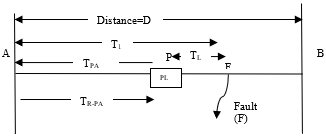
2. PLG connected between equal distance (at Pont P) (Figure1) from two sub-stations A and B. Please follow below cases how Hybrid AD method help to detect location of fault.
Case 1: Fault occurred between Station A and PLG
Step 1: When Downed or Broken power line Fault not touching the ground occurred (at Point F) (Figure 2) at that point 2nd harmonic first travelling wave generated and travelled towards Station A and Station B (Figure 2).
Step 2: measure 2nd harmonic first forward travelling wave timing between fault point “F” to PLG Point “P”.
Step 3: measure 2nd harmonic first forward travelling wave from fault point “F” to Station B.
Step 4: measure first reflected travelling wave from station B to fault point (at point F).
Step 5: measure first reflected travelling wave from station B to at Point P.
Figure 1. PLG between two substations
Figure 2. Type AD Method for fault near to station B
D=Total distance between station A and Station B[m]; DX= Fault location distance from Station B[m]
F=Fault point location, P=Power Line Guardian arranged on transmission line; TL =First forward travelling wave time between Fault point (F) and PLG point (P) [s]
TPB=First forward travelling wave time between PLG point (P) and Station B[s]; TR-PB =First reflected travelling wave time between PLG point (P) and Station B[s]
T=First forward travelling wave time between Fault point (F) and Station B[s]; PLG= Power Line Guardian, V = wave velocity [m/s], $T_x$=Total travelling time [s], $T_x=(\frac{T_{PB}+T_R-_{PB}}{2}+T_L)/10$ ,
Fault location distance from Station B $D_X=T_x$ $.V$
Case 2: Fault occurred between Station B and PLG.
Step 1: When Downed or Broken power line Fault not touching the ground occurred (at Point F) (Figure 3) at that point 2nd harmonic first travelling wave generated and travelled towards Station A and Station B (Figure 3).
Step 2: measure 2nd harmonic first forward travelling wave timing between fault point “F” to PLG Point “P”
Step 3: measure 2nd harmonic first forward travelling wave from fault point “F” to Station A
Step 4: measure first reflected travelling wave from station A to fault point (at point F)
Step 5: measure first reflected travelling wave from station A to at Point P
Figure 3. Type AD Method for fault near to station A
D=Total distance between station A and Station B[m]; DX= Fault location distance from Station B[m]
F=Fault point location; P= Power Line Guardian arranged on transmission line; TL =First forward travelling wave time between Fault point (F) and PLG point (P) [s]
TPA=First forward travelling wave time between PLG point (P) and Station A [s]; TR-PA = First reflected Travelling wave time between PLG point (P) and Station A[s].
T1=First forward travelling wave time between Fault point (F) and Station A[s]; PLG= Power Line Guardian, V= wave velocity [m/s], $T_x$=Total travelling time [s], $T_x=(\frac{T_{PA}+T_R-_{PA}}{2}+T_L)/10$ ,
Fault location distance from Station A $D_X=T_x$ $.V$
We used PSCAD V4.2 for this simulation results. if we apply in Theoretical calculation to simulation for Case 1, Distance between station A and B is 100 Kilo meters. If Downed or Broken power line Fault not touching the ground occurred at 25 Km from Station A
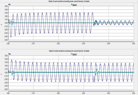
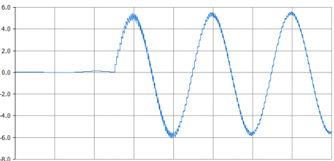
Figure 4. 2nd harmonic wave Generated at fault point
Figure 5. First forward Travelling wave travelling towards station B
Figure 4 and Figure 5. Explains how 2nd harmonic generated at fault point and fault travelling wave travelling towards station B.
From Simulation Results, $T_{PB}=0.188ms$, $T_{R-PB}=0.376ms$, $T_L=0.6837ms$, $T_x=(\frac{T_{PB}+T_R-_{PB}}{2}+T_L)/10$, Fault location distance from Station B $D_X=T_x$ $.V$=28.97 KM. Final value near to fault location.
In Smart grid, Fault location finding methods using travelling wave concept but all methods measuring travelling wave at end of source or destination. As compare to all that methods, my proposed Hybrid AD Method measure travelling wave at middle of Transmission line length. At present very, few methods for finding exact location of Downed power lines Fault without touching ground. As compare to all of that’s methods and process, the proposed solution will give better Solution, economic and within less time. I hope it will give almost 100% accurate solution for finding exact location Detect Downed power lines Fault without touching ground. This Paper provides solution used for between two substations. Further Research work will be finding exact location of Downed power lines Fault without touching ground between substations to rural area.
We would like to thank Siemens AG, Germany & Siemens Technology and Services Pvt Ltd, India sponsored for my research work & National institute of Technology, Jamshedpur supported my research work.
[1] Arehart RF. (1989). Downed power lines: Why they can’t always be detected. IEEE Transactions.
[2] O’Brien W, Udren E, Garg K, Haes D, Sridharan B. (2016). Catching falling conductors in midair-detecting and tripping broken distribution circuit conductors at protection speeds. 2016 69th Annual Conference for Protective Relay Engineers (CPRE), pp. 20-22. https://doi.org/10.1109/CPRE.2016.7914881
[3] Tengdin J. (1989). Detection of downed conductors on utility distribution systems. IEEE PES Tutorial course 90EH0310-3-PWR.
[4] Cook B, Garg K. (2013). Designing a special protection system to mitigate high interconnection loading under extreme conditions-a scalable approach. Proceedings of the 40th Annual Western Protective Relay Conference.
[5] Hou DQ. (2006). Detection of high-impedance faults in power distribution systems. 2007 Power Systems Conference: Advanced Metering, Protection, Control, Communication, and Distributed Resources. https://doi.org/10.1109/PSAMP.2007.4740902
[6] Covington T, Stankiewicz T, Anderson R, Wright L, Cockerham B. (2017). A simple method for determining fault location on distribution lines. Proceedings of the 71st Annual Georgia Tech, Protective Relaying conference as an alternate.
[7] Anderson PM. (1995). Analysis of faulted power system. IEEE press New York.
[8] Ajenikoko GA, Sangotola SO. (2016). An overview of impedance-based fault location techniques in electrical power- transmission network. International Journal of Advanced Engineering Research and Applications (IJA-ERA) 2(3): 2454-2377.
[9] Deepika KK, Kumar JV, Rao GK. (2017). A review on applications of PMUs in impedance-based fault location in transmission lines. International Journal of Pure and Applied Mathematics 114(8): 93-100.
[10] Saha MM, Das R, Verho P, Novosel D. (2002). Review of fault location techniques for distribution systems. Power Systems and Communications Infrastructures for the future.
[11] Zimmerman K, Costello D. (2006). Impedance-based fault location experience. 2006 Rural Electric Power Conference, pp. 9-11. https://doi.org/10.1109/CPRE.2005.1430435
[12] Roostaee S, Thomas MS, Mehfuz S. (2017). Experimental studies on impedance-based fault location for long transmission lines. Protection and Control of Modern Power Systems 2: 16. https://doi.org/10.1186/s41601-017-0048-y
[13] Goh HH, Sim SY, Mohamed MAH, Rahman AKA, Ling CW, Chua QS, Goh KC. (2017). Fault location techniques in electrical power system: A review. Indonesian Journal of Electrical Engineering and Computer Science 8(1): 206-212.
[14] Dugan RC, McGranaghan MF, Santoso S, Beaty HW. (1996). Electrical Power Systems Quality. McGraw-Hill Education.
[15] Röhrig J. (1931). Location of faulty places by measuring with cathode ray oscillographs. Elektrotech Zeits 8: 241-242.
[16] Ando M, Schweitzer EO, Baker RA. (1985). Development and field-data evaluation of single-end fault locator for two-thermal HVDC transmission lines, part i: Data collection system and field data. IEEE Transactions on Power Apparatus and Systems PAS-104(12): 3524-3530. https://doi.org/10.1109/TPAS.1985.318905
[17] Ando M, Schweitzer E, Baker RA. (1985). Development and field-data evaluation of single-end fault locator for two-terminal HVDV transmission lines-part 2: Algorithm and evaluation. IEEE Transactions on Power Apparatus and Systems PAS-104(12): 3531-3537. https://doi.org/10.1109/TPAS.1985.318905
[18] Krzysztof G, Kowalik R, Rasolomampionona D, Anwar S. (2011). Traveling wave fault location in power transmission systems: An overview. J. Electrical Systems 7-3: 287-296.
[19] Barburas I, Petrovan, TM, Nasui I, Bugnar S, Zah IN, Boiciuc I. (2015). Detecting the fault location using Traveling wave. 6th International Conference on Moderan Power systems MP2015, pp. 18-21.
[20] Xu BY, Xue YD, Li J, Yan TC, Gale P. (2005). Fault location on railway power lines using travelling wave transients. CIRED 2005 - 18th International Conference and Exhibition on Electricity Distribution, pp. 6-9. https://doi.org/10.1049/cp:20051190
[21] Andrade LD, Leão TPD. (2012). Travelling wave based fault location analysis for transmission lines. EPJ Web of Conferences 33: 9.
[22] Packard H. (1997). Traveling Wave Fault Location in Power Transmission Systems. Application Note 1285.
[23] Hossley P, Davidson M, Gale P. (1993). Fault location using travelling waves. The Smithsonian/NASA Astrophysics Data System.
[24] Bollen MHJ. (1989). On travelling-wave-based protection of high-voltage networks. Technische Universiteit Eindhoven.
[25] Ma G, Jiang LR, Zhou KH, Xu GC. (2016). A method of line fault location based on traveling wave theory. International Journal of Control and Automation 9(2): 261-270.
[26] Costa FB, Souza BA. (2011). Fault-induced transient analysis for real-time fault detection and location in transmission lines. International Conference on Power Systems Transients (IPST’11) in Delft.
[27] Baseer MA. (2013). Travelling waves for finding the fault location in transmission lines. Journal Electrical and Electronic Engineering 1(1): 1-19. https://doi.org/10.11648/j.jeee.20130101.11
[28] Papaleonidopoulos IC, Theodorou NJ, Capsalis CN. (2013). Travelling-wave modelling of uniform multi conductor transmission line networks-Part II: Experimental validation-applicability. Progress in Electromagnetics Research B 52: 295-305. https://doi.org/10.2528/PIERB13012008
[29] Gale PF, Stokoe J, Crossley PA. (1997). Practical experience with travelling wave fault locators on Scottish power’s 275 & 400 KV transmission system. 6th International Conference on Developments in Power Systems Protection, pp. 192-196. https://doi.org/10.1049/cp:19970061
[30] Idris MH, Mustafa MW, Yatim Y. (2012). Effective Two-Terminal Single Line to Ground Fault Location Algorithm. 2012 IEEE International Power Engineering and Optimization Conference Melaka, Malaysia. https://doi.org/10.1109/PEOCO.2012.6230869
[31] Kawady T, Stenzel J. (2002). Investigation of practical problems for digital fault location algorithms based on EMTP simulation. IEEE/PES Transmission and Distribution Conference and Exhibition 1: 118-123. https://doi.org/10.1109/TDC.2002.1178270
[32] Aurangzeb M, Crossley PA, Gale P. (2001). Fault location using the high frequency travelling waves measured at a single location on a transmission line. 7th International Conference on Developments in Power Systems Protection (DPSP 2001): 403-406. https://doi.org/10.1049/cp:20010185
[33] Redfem MA, Terry SC, Robinson FVP. (2004). The application of distribution system current transformers for high frequency transient based protection. Eighth IEE International Conference on Developments in Power System Protection, pp. 108-111. https://doi.org/10.1049/cp:20040075
[34] Milioudis AN, Andreou GT, Labridis DP. (2012). Enhanced protection scheme for smart grids using power line communications techniques-part i: Detection of high impedance fault occurrence. IEEE Transactions on Smart Grid 3(4): 1621-1630. https://doi.org/10.1109/TSG.2012.2208987
[35] Dolezilek DJ, Schweitzer S. (2009). Practical applications of smart grid technologies. Smart Grid RoadShow 2(1): 1-7.
[36] Zavoda F. (2011). Sensors and IEDs required by smart distribution applications. The First International Conference on Smart Grids, Green Communications and IT Energy-aware Technologies.
[37] Holey DM, Chandrakar VK. (2016). Harmonic analysis techniques of power system-a review. International Research Journal of Engineering and Technology (IRJET) 3(2): 680-684.
[38] Ellis RG. (1996). Harmonic: Analysis of industrial power systems. IEEE Transactions on Industry Applications 32(2): 417-421. https://doi.org/10.1109/28.491492
[39] Al-duaij EOS. (2015). Harmonics effects in power system. Journal of Engineering Research and Applications 5(2): 1-19.
[40] Acha E, Madrigal M. (2001). Power systems harmonics.
[41] Nuthalapati1 B, Sinha UK. (2018). Detection of downed or Broken power line Fault not touching the ground. Journal Européen des Systèmes Automatisés 51(4-6): 309-321. https://doi.org/10.3166/JESA.51.309-321
[42] Nuthalapati B, Sinha UK. (2018). Location and detection of downed power line fault not touching the ground. European Journal of Electrical Engineering 20(3): 347-362. https://doi.org/10.3166/ EJEE.20.347-362