Nawel Chikhi | Abdelber Bendaoud*
OPEN ACCESS
This work aims to investigate the electromagnetic disturbances generated by a rectifier-chopper association. Electromagnetic conducted emissions are a phenomenon that is difficult to predict, particularly within a complex power grid which includes static converters, considered to be the origin of these disturbances. In this paper, the EMC behavior of a switching cell is studied, using both experiments and simulations. A comparison results is also presented. Shape and amplitude of disturbances carried out will play an important role in the propagation phenomena of disturbances over a network using a Line Impedance Stabilizer Network (LISN), simulations have been done with Ltspice software. The results underscore that the nature of disturbances induced in the network is dependent on the operating region of the bridge.
The main conclusion of this work is that this device is really electromagnetic pollutant and must then be taken into account, as a whole, in any study implying this kind of converters.
The results will be used in optimizing the dimensions of EMC filters to be placed at the input side of the converter depending on the network and converter's impedances.
electromagnetic compatibility, static converters, LISN, simulation, experimental, switching, waveforms, DC motor
Today, Electromagnetic Compatibility (EMC) seems to be one of the major constraints of power electronics converters. Unfortunately, it is too often regarded as the last phase in the development of a converter since it represents the last step of its marketing. From an economic point of view, the estimation of conducted and radiated disturbances by simulation offers an important advantage [1, 2].
The conducted EMI noise, generated by power electronic converters, connected to the grid, seems to be as parasitic harmonic sources of current or voltage, circulating inside electrical networks and shielding structures. In addition, new constraints begin to appear related to modern network design, including increasable power electronic converters. Power electronic converters are widely used in many applications including renewable energy generation, industrial equipment/motor drives, electric vehicles/trains, air-crafts, household appliances, electronic ballasts, computer power supplies, power supplies for telecommunication equipment, etc. These power converters use fast switching power semiconductor switches, such as MOSFET (Metal-oxide semiconductor field effect transistor), IGBT (Insulated Gate Bipolar Transistor) as the preferred switching devices because of their various properties, such as higher efficiency, smaller size, and lower overall cost, low losses associated with switching device. However, the fast switching speed of new converter technologies has the potential to cause EMI and high dv/dt [3-6].
With the development of new sources of renewable energy, more static converters are connected to the power network. They supply of the network with electric power produced by generators; but in contrast to conventional systems, they usually introduce low frequency (LF) and high frequency (HF) switching harmonics [7-9].
Several works have focused on the electromagnetic disturbances generated by a rectifier-chopper association, but the objectives and the associated frequency band vary widely. The study in [1] investigated emissions conducted to the network.
This study covers the problem of conducted disturbances propagated along an electrical network using the LISN. The identification of the impedance of a single phase of electrical network is based on an experimental method introduced in the research works of reference [1].
The simulation has been done using accurate models of all components of the circuit, what allows to observe chosen voltage and current. The generation and properties of conducted disturbances have been analyzed. The impact of chosen components on perturbation level has been presented. The results from simulation and measurement have been compared.
This paper is organized as follows: Section 2 describes a simple switching cell filtered by a capacitor together with the waveforms associated with this structure. Section 3 introduces an evaluation of EMC effects on an electrical network introduced by associating two polluting devices: rectifier and chopper. Sections 4 describe the results and analysis for the rectifier bridge in the passing state and rectifier bridge in the half blocked state. Finally, Section 5 presents some conclusions and some recommendations for future studies.
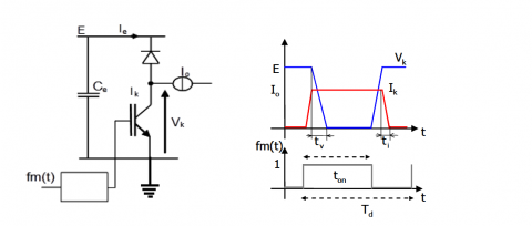
The harmonics Energy conversion in power electronics is based on two complementary stages, power switching and storage. Switching is done by semiconductors based power switches. Figure 1 shows a simple switching cell filtered by a capacitor together with the waveforms associated with this structure.
Figure 1. Switching cell and associated waveforms
The main switch is controlled by a periodic modulation function Fm(t) with Td as the binary period value and α=ton/Td as a variable duty cycle. This duty cycle modulates the power transfer.
For simplification, the external switching cell values (E, I0) are considered constant while internal ones (ie, vk) are taken as variables modulated by the fm(t) function [10-13].
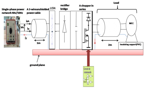
In this part of the study, we present an evaluation of EMC effects on an electrical network introduced by associating two polluting devices: a rectifier and a chopper. The purpose of this work is to investigate the impact of the EMC on a variable speed drive system when connected to single phased electrical network using a LISN together with analysis of disturbances generated by the switching cell as shown in Figure 2.
The experimental set up is placed in EMC normative measurement conditions (Figure 3). The rectifier, in series chopper along with the connecting cables are placed on a plane of 2 m2 which is electrically grounded, representing an ideal grounding or a metallic environment as in the case of an on-board network.
Figure 2. Experimental set up with a chopper connected to a network by using a LISN
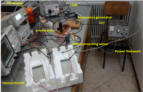
Figure 3. Photograph of Experimental EMC set up
To provide insulation from the ground and ensure no common-mode current is returned to the disturbance source by the grounding plane where current measurement is difficult to do, the motor is placed on a 5 cm thick PVC plate.
The experimental set up presented in figure 3 is made up of the following components:
A chopper in series composed of a MOSFET IRFP240 transistor switching at a frequency of 20 kHz and an FST30100 diode (Schottky diode 30A /100V/ TO247). The rectifier bridge includes a single phase diode (KBPC 5010) together with a filter capacitor of 1000 μF for the DC bus. The converter is loaded on a 2 m length of a 3 wire unshielded power cable (Figure 4) and a DC motor (0.1 kW, 0.63 A, 220 V). The modeling method of the conductors presented in the research works of reference [13] was used. The set-up is connected to a 40V/50 kHz network. A 3 wire unshielded power cable (Figure 4) of 1 m connects the converter to the network.
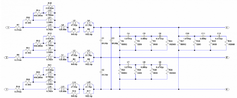
Figure 4. Basic cell of a 3 wire unshielded cable (2 cells per meter) [13]
The experimental validation is based on time-domain simulation under LTspice software for the entire conversion system using LTspice power switchers (MOSFET and diode) available in the software. However the rectified voltage and the input rectifier bridge voltage waveforms are distorted by abrupt changes due to MOSFET and diodes switching.
A zoom in on the corresponding to the switching time interval shows a periodic and oscillatory phenomenon is visible
This phenomenon is due to brutal switching of switches and to the effects of connecting inductors and passive components of converters [14-20].
Hence, by modeling the impedance circuit of a single phase of electrical network and different HF models making up the system presented in the research work of the reference [1]. It's possible to simulate the behavior of the entire conversion system for the different operating regions of the diode-based rectifier bridge. In what follows, a comparison between time-domain simulation of the studied system and experimental results was presented. The waveforms of the ground current iT at the network side and those of the network voltage iT will be thus presented successively.
The present work will particularly be interested in the waveforms generated by two types of MOSFET switching for the two operating regions of a diode-based rectifier bridge: passing and half-blocked [21-25].
4.1 Rectifier bridge in the passing state
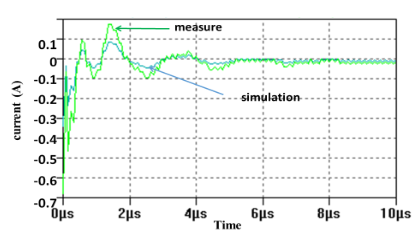
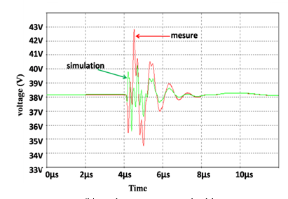
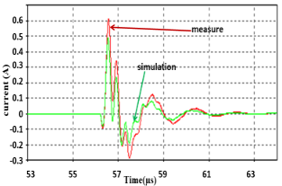
Figures 5 and 6 show the waveforms of the grounded current iT and voltage VR produced by simulation using LTspice models of the MOSFET and the diode for both types of switching when the rectifier bridge is in the passing state compared to the waveforms given by measurement.
(a) Grounded current iT network side
(b) Voltage VR network side.
Figure 5. Comparison of the simulation and experimental waveforms for iT and VR for the switching to blocking of the MOSFET (Rectifier Bridge in passing state)
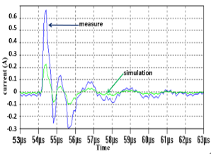
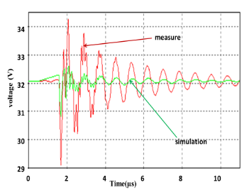
Figure 6 shows the experimental and simulated waveforms of the current iT and the voltage VR. It may also be observed that a comparison of the waveform of current and voltage in the time.
The consistency of the results shows that the model ensures good reproducibility of the disturbances. Other factors may contribute to the observed discrepancies such as cabling, routing, environment noises, etc., which were not accounted for during the simulation.
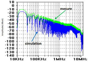
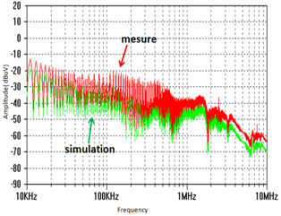
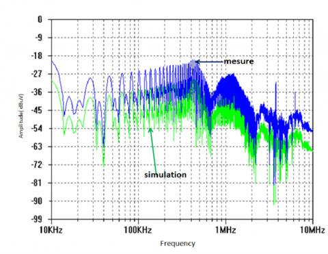
Figure 7 shows a comparison between simulated and measured iT and VR values in the frequency domain after FFT calculation. It can be observed that the shape of the disturbances decreases with increasing frequency. However, the amplitudes and the frequency of the oscillation present a slight difference.
(a) Grounded current iT
(b) Voltage VR
Figure 6. Comparison of the simulation and experimental waveforms of iT and VR during the switching to conduction of the MOSFET (Rectifier Bridge in passing state)
(a) FFT of iT current
(b) FFT of voltage VR
Figure 7. Comparison of the simulation and experimental waveforms of iT and VR in the frequency domain (Rectifier Bridge in passing state)
A comparison of the simulation and the experimental results shows good behavior of the proposed models in the time and frequency domains.
4.2 Rectifier bridge in the half blocked state
Figures 8 and 9 show a comparison of iT and VR waveforms during switching of the MOSFET in conduction when the rectifier bridge is in the half-blocked state.
(a) Grounded current iT
(b) Voltage VR
Figure 8. Comparison of the simulation and experimental waveforms of iT and VR during the switching to blocking of the MOSFET (Rectifier Bridge in the half blocked state)
(a) Grounded current iT
(b) Voltage VR.
Figure 9. Comparison of the simulation and experimental waveforms of iT and VR during the switching of the MOSFET to conduction (rectifier bridge in the half blocked state)
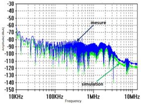
(a) FFT of current iT.
(b) FFT of voltage.
Figure 10. Comparison of simulation/experimental waveforms of iT and VR in the frequency domain (Rectifier Bridge in the half blocked state
The conclusion that can be drawn is similar to the previous one, except for the differences in amplitude seen in Figure 8 (a) and (b) as well as in figure 9 (b).
The comparison in the frequency domain is given in figure 10. We can see a discrepancy in the voltage spectrum VR (Figure 10 (b)).
This work concerns an EMC study of a chopper in series supplying a DC motor. The conversion system is directly connected to a single phase of electrical network by using a LISN. We have used simulation to investigate the propagation of the disturbances along the network and particularly, the influence of the diode-based rectifier bridge on this propagation. The results underscore that the nature of disturbances induced in the network is dependent on the operating region of the bridge.
The experimental validation has highlighted the difficulty of modeling the disturbances propagation for converters connected to the network. The experimental results have been shown and compared to those of the simulation. The comparison may be considered as acceptable. Indeed, the model gives a fair representation of the measured disturbances. The identification of interferences sources in an electrical device is not always obvious. In power electronics, the major disturbances are caused by the changes of state of the switches in the power converter. These sudden tilting brings rapid changes in current or voltage at the terminals of the different components.
Following this study, it may be interesting to focus on developing the simulation method, it will be necessary to validate the method on other multi-cell circuits.
|
EMC FFT fm(t) |
Electromagnetic compatibility Fast Fourier Transform a periodic modulation function |
|
Td |
a period value, s |
|
fm(t) (E, I0) (ie, vk) VR iT dv/dt |
modulation function the external values of the switching cell internal values(variables) Voltage network side, V Grounded current network side, A the instantaneous rate of voltage change over time, V.S-1 |
|
Greek symbols |
|
|
a |
duty cycle |
[1] Moreau M. (2009). Modélisation haute fréquence des convertisseurs d’énergie. Application à l’étude des émissions conduites vers le réseau. PHD Thesis, Electrical Engineering, Central School of Lille-France.
[2] Muttaqi KM, Haque ME. (2008). Electromagnetic interference generated from fast switching power electronic devices. International Journal of Innovations in Energy Systems and Power 3(1): 19-45.
[3] Fakhfakh L, Amous A. (2016). New simplified model for predicting conducted EMI in DC/DC converters. Electrical Engineering 99(3): 1087-1097. http://dx.doi.org/10.1007/s00202-016-0474-2
[4] Haque ME, Bokhari AA, Alolah AI. (2005). Simulink modeling of the problem associated with fast switching PWM IGBT-inverter fed AC motor drive with long cable and its remedies. IEEE International conference on Systems, Signals & Devices, Sousse-Tunisia.
[5] Boroyevich D, Zhang X, Bishinoi H, Burgos R, Mattavelli P, Wang F. (2014). Conducted EMI and systems integration. CIPS 2014 8th International Conference, Nurenberg.
[6] Ales A, Gouichiche Z, Karouche B, Moussaoui D, Schanen JL, Roudet J. (2015). The accurate input impedances of a DC- DC converters connected to the network. IEEE 15th International Conference on Environment and Electrical Engineering (EEEIC), Rome, Italy. http://dx.doi.org/10.1109/EEEIC.2015.7165183
[7] Christopoulos C, Bradley KJ, Clare JC, Gokani S, Ran L. (1996). Conducted emission measurements in the power electronics environment. EMC Testing for Conducted Mechanisms Conference. http://dx.doi.org/10.1049/ic:19960730
[8] Benhadda N, Bendaoud A, Chikhi N. (2018). A conducted EMI noise prediction in DC/DC converter using a frequency-domain approach. Elektrotehniški Vestnik Journal 85(3): 103-108.
[9] Mahesh G, Subbarao B, Karunakaran S. (2008). Effect of power frequency harmonics in Conducted Emission measurement. 2008 10th International Conference on Electromagnetic Interference & Compatibility, pp. 273-277.
[10] Liu Q, Wang F, Boroyevich D. (2006). Modular-Terminal-Behavioral (MTB) model for characterizing switching module conducted EMI generation in converter systems. IEEE Transactions on Power Electronics 21(6): 1804-1814. http://doi.org/10.1109/TPEL.2006.882903
[11] Miloudi M, Bendaoud A, Miloudi H. (2017). Common and differential modes of conducted electromagnetic interference in switching power converters. Revue Roumaine Science Technique – Électrotechnique. et Énergétique 62(3): 246–251.
[12] Rondon-Pinilla E. (2014). Conception de convertisseurs électroniques de puissance à faible impact électromagnétique intégrant de nouvelles technologies d’interrupteurs à semi-conducteurs. Thèse de doctorat de l’Université de Lyon.
[13] Weens Y. (2006). Modélisation des Câbles d’Energie Soumis aux Contraintes Générées par les Convertisseurs Electroniques de Puissance. Thèse de Doctorat de l’Université des Sciences et Technologies de Lille (L2EP).
[14] Liu T, Ning R, Wong TTY, Shen ZJ. (2016). Equivalent circuit models and model validation of SiC MOSFET oscillation phenomenon. 2016 IEEE Energy Conversion Congress and Exposition (ECCE), Milwaukee, WI, USA. http://dx.doi.org/10.1109/ECCE.2016.7855086
[15] Chikhi N, Bendaoud A, Slimani H, Benazza B, Miloudi H. (2015). Génération des perturbations dans un hacheur et identification des chemins de propagation vers le réseau électrique. 9th Conference on Electrical Engineering EMP, Bordj El Bahri, Algiers.
[16] Slimani H, Bendaoud A, Reguig A, Benazza B, Reineix A, Dafif O. (2016). Experimental study of coupling between an electromagnetic wave and transmission lines in a GTEM cell. Journal of Electrical Engineering 16(1): 195-203.
[17] Zhang DB, Chen DY, Nave MJ, Sable D. (2000). Measurement of noise source impedance of off-line converters. APEC '98 Thirteenth Annual Applied Power Electronics Conference and Exposition, Anaheim, CA, USA. https://doi.org/10.1109/APEC.1998.654007
[18] Fedyczak Z, Kempski A, Smoleński R. (2013). Conducted high frequency disturbances observed in electrical power systems with switch mode converters. Przegląd Elektrotechniczny, R. 89 NR 6/2013, 41-50.
[19] Moreau M, Videt A, Idir N, Franchaud JJ, Le Moigne P. (2008). Equivalent EMI noise source modelling in power converters. Int. Conf. PCIM, Nuremberg.
[20] Fakhfakh L, Alahal A, Amous A. (2016). Fast modeling of conducted EMI phenomena using improved classical models. 2016 Asia-Pacific International Symposium on Electromagnetic Compatibility (APEMC), Shenzhen, China. http://dx.doi.org/10.1109/APEMC.2016.7522795
[21] Miloudi H, Bendaoud A, Miloudi M. (2017). A method for modeling a common-mode impedance for the AC motor. Elektrotehniški Vestnik Journal 84(5): 241-246.
[22] Foissac M, Schanen JL, Frantz G, Frey D, Vollaire C. (2011). System Simulation for EMC Network Analysis. 2011 Twenty-Sixth Annual IEEE Applied Power Electronics Conference and Exposition (APEC), Fort Worth, TX, USA.
http://dx.doi.org/10.1109/APEC.2011.5744636
[23] Mrad R, Morel F, Pillonnet G, Vollaire C, Lombard P, Nagari A. (2013). N-conductor passive circuit modeling for power converter current prediction and EMI aspect. Electromagnetic Compatibility, IEEE Transactions on 55(6): 1169-1177.
http://dx.doi.org/10.1109/TEMC.2013.2265048
[24] Duan Z, Fan T, Zhang D, Wen X. (2017). Differential mode conducted EMI prediction in three phase SiC inverters. IOP Conference Series: Materials Science and Engineering 199: 012126.
http://dx.doi.org/10.1088/1757-899X/199/1/012126
[25] Miloudi H, Bendaoud A, Miloudi M. (2014). Réduction des perturbation électromagnétique conduites dans la machine asynchrone. Mediterranean Journal of Modeling and Simulation MJMS 2: 8-15.