Zhilei Wang![]() | Chuangju Zhang
| Chuangju Zhang![]() | Duoxin Zhang*
| Duoxin Zhang*![]()
© 2023 IIETA. This article is published by IIETA and is licensed under the CC BY 4.0 license (http://creativecommons.org/licenses/by/4.0/).
OPEN ACCESS
This paper discusses the influence of different seismic waves on the seismic response of the aqueduct structure, finds out the most unfavorable working conditions through the analysis of the dynamic characteristics of the aqueduct, selects three different seismic waves in line with the site conditions of the project, and calculates and analyzes the most unfavorable working conditions of the aqueduct under two different support modes. The following conclusions are drawn: when the ordinary basin rubber bearing scheme is adopted, the seismic response of the aqueduct structure under different seismic wave excitation is different, and the response value is large. The maximum tensile stress at individual positions is close to the design value of the tensile strength of the concrete of the aqueduct body, so there is a certain risk; After adopting the high damping isolation bearing, the change of the aqueduct structure is relatively stable, the maximum tensile stress decreases a lot, and the maximum value is controlled at about 0.7MPa. Its hysteretic curve is full, and the energy dissipation and damping effect is obvious, which can ensure that the aqueduct structure will not be damaged under the earthquake.
aqueduct, dynamic characteristic analysis, different seismic waves, high damping rubber bearing, seismic response
Earthquake is one of the most destructive natural disasters known to mankind, and it cannot be predicted well. Once a severe earthquake occurs, it will seriously threaten human survival [1]. The Dianzhong Water Diversion Project currently under construction is based on a 50-year exceedance probability of 10% for the basic seismic intensity, and the project is located in an area with a peak acceleration of 0.2g at 8 degrees. As the "throat" project of the water diversion project, if an accident occurs in the aqueduct, it will cause the entire water delivery line to be interrupted, resulting in immeasurable losses. Therefore, ensuring the normal use of the aqueduct under various load conditions during its design service life is of great significance.
Currently, the system of seismic isolation, energy dissipation and damping, and structural control technology is one of the most important innovations in earthquake engineering in the world in the past 40 years [2]. Over the last hundred years, many scholars at home and abroad have made certain achievements after field investigations and summary reflections on the seismic design of building structures and continuous exploration and research on design theories and new systems of structural seismic resistance. Liu et al. [3] used the bilinear principal structure model of LRB and analyzed the seismic isolation performance of LRB in the aqueduct project, showing that LRB has good seismic isolation for large ferries, the seismic response of large ferries varies with the LRB, and there is a potential for preferring LRB in the project; Zheng et al. [4], in order to solve the problem of excessive displacement of ferries with seismic isolation bearings under seismic action In order to solve the problem of excessive displacements of the aqueduct with seismic isolation bearings, seismic analysis of the aqueduct was carried out using an intelligent seismic isolation control system composed of seismic isolation bearings and magnetorheological dampers (MR dampers), which showed that the intelligent seismic isolation system could effectively reduce the seismic action and the lateral displacement of the aqueduct, and could significantly reduce the maximum shear force at the bottom of the pier. In terms of bearing design, Zhang et al. [5] designed SDBs with high vertical bearing capacity, low horizontal shear stiffness, and certain damping and resetting capabilities, and showed through calculations that the installation of SDBs in a large aqueduct can significantly reduce the stress response of the aqueduct structure and ensure the safe operation of the aqueduct structure under seismic effects. Liu and Wang [6] studied the seismic reduction effect of seismic isolation bearings and determined the design mechanical parameters of FPB for the South-North Water Transfer Double Cook River crossing, and proved that FPB can reduce the fundamental frequency of the crossing structure, change its dynamic characteristics, and reduce the seismic response of the crossing body and the pier of the crossing to a greater extent, thus improving the seismic safety of the large crossing structure. Huang et al. [7] compared the seismic damping effect of RB, tetrafluoro-plate rubber bearing and LRB, and showed that the seismic damping effect of LRB was better and reached the expected design goal.
Theory and practice show that the use of seismic isolation bearings, energy dissipation and damping devices and structural control techniques can well reduce the seismic response of large ferries and improve the overall seismic performance of ferries. However, the seismic isolation and damping mechanism of a large aqueduct is closely related to the dynamic characteristics of the structural system of the aqueduct, the spectral characteristics of the ground vibration, and the structural form of the aqueduct. The time analysis of the structure of the aqueduct is input in the form of acceleration time for the seismic load, and the results are greatly influenced by different seismic waves, so the selection of seismic waves is especially important. In this paper, in order to study the seismic isolation effect of common basin type rubber bearing and high damping bearing crossings under the action of different seismic waves, a general finite element program ANSYS is used to build a model and select different seismic waves as input for the seismic response time analysis of the crossings structure in the background of Dongjiacun crossings project.
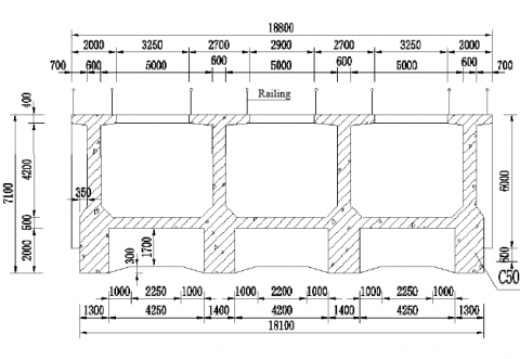
Dongjiacun aqueduct is located at about 1km north of Pindianhai, Yunnan Province, and the basic intensity of earthquake is Ⅷ degree. Crossing Dongjiacun turnip ditch, the design flow is 120m3/s, the aqueduct adopts simple-supported beam type aqueduct structure, the pier adopts solid gravity pier, the foundation selects the pile foundation treatment to strengthen. The total length of the channel body is 238.943m, and the span of the single-span channel is 30m, which is a simple-supported prestressed C50 concrete structure with three boxes of rectangular section type, totaling 8 spans, and the net size of the section is 3×5.2m×4.4m (number of holes×width×height), and the specific section size is shown in Figures 1 to 4.
Figure 1. Cross-sectional drawing of the span of the aqueduct structure
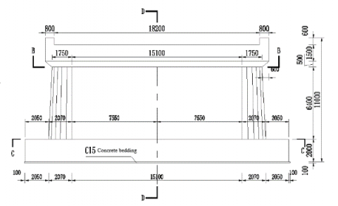
Figure 2. Cross section of the aqueduct structure across the end
Figure 3. Longitudinal schematic diagram of the structure of the aqueduct
Figure 4. Elevation of aqueduct channel pier structure
3.1 Parameter selection
(1) Slot body parameters: C50 concrete is used for the body of the aqueduct trough, C30 concrete is used for the pier on the trough pier, and C25 concrete is used for the pier of the aqueduct, with the specific parameters shown in Table 1.
Table 1. Material parameters of each part of the aqueduct
|
Part |
Material |
Density( kg/m3) |
Poisson's ratio |
Modulus of elasticity(GPa) |
|
Aqueduct body |
C50 Concrete |
2500 |
0.167 |
34.5 |
|
Aqueduct piers |
C30 Concrete |
2500 |
0.167 |
30 |
|
Aqueduct pier body |
C25 Concrete |
2500 |
0.167 |
29 |
Note: The above modulus of elasticity was static elastic modulus, and the dynamic elastic modulus is 1.3 times of the static elastic modulus for dynamic analysis.
(2) Support parameters: In this paper, two types of bearings are used in the research process: ordinary basin type rubber bearing and high damping vibration isolation rubber bearing. The specific stiffness parameters of the two types of bearings are shown in Table 2 and Table 3 below:
Table 2. Ordinary basin type rubber bearing stiffness parameters table
|
|
x |
z |
y |
|
Stiffness(N/mm) |
2.72×10⁸ |
2.72×10⁸ |
6×10⁸ |
Table 3. Parameters of high damping rubber vibration isolation bearing
|
Support parameters |
Takes values |
|
Design shear displacement ${x}_0 /{mm}$ |
209 |
|
Allowable shear displacement ${x}_1 /{mm}$ |
522 |
|
Ultimate shear displacement ${x}_2 /{mm}$ |
731 |
|
Horizontal yielding force ${Q}_0 /{kN}$ |
474 |
|
Vertical compression stiffness $K_v/({kN} /{mm})$ |
1642 |
|
Initial horizontal stiffness $K_1/({kN} /{mm})$ |
24.79 |
|
Horizontal stiffness after yielding $K_2/({kN} /{mm})$ |
2.92 |
|
Equivalent damping ratio $\xi / \%$ |
17 |
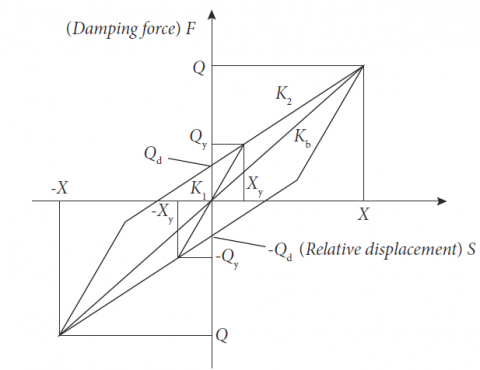
Figure 5. Equivalent bilinear restoring force
Among them, the high damping vibration isolation rubber bearing is selected according to the literature [8], and the type bearing is selected as the vibration isolation and damping bearing for the large aqueduct in this paper, and the bilinear restoring force model of this bearing is shown in Figure 5.
3.2 Dynamic analysis model
In order to eliminate the influence of boundary selection on the structural dynamic calculation, this study takes a three-span aqueduct as a calculation unit for analysis. Using the consistent excitation method for analysis, the study establishes a three-span three-dimensional finite element model of the Dongjiacun aqueduct in the whole section of eight spans, and the trough body, trough pier and the finite soil body of the foundation are simulated by using three-dimensional solid units, and for the common basin rubber bearing and the high damping vibration isolation bearing, a spring unit is used to combine the simulation to achieve. For how the soil body can be selected to approximate the actual situation instead of infinity, according to the relevant research results [9], this paper intends to establish the three-dimensional finite element model shown in Figure 6 below.
Figure 6. 3D finite element model
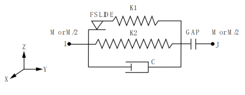
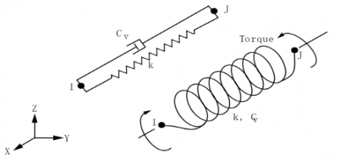
In particular, since there are no ready-made units for seismic isolation bearings in ANSYS. Considering that the mechanical model of the seismic isolation bearing can be simplified to consist of nonlinear springs in both horizontal directions, viscous dampers and linear springs in the vertical direction, and ANSYS provides a series of connection units such as spring damping. Therefore, this paper adopts the combination of several units to realize the simulation of the vibration isolation bearing. The combin40 unit is used in both horizontal directions, which can introduce the influence of bilinear strengthening model and viscous damping. The basic seismic isolation parameters are mainly Ku (pre-yield stiffness), Kd (post-yield stiffness), Qd (yield force), and damping ratio. From the combin40 mechanical schematic (see Figure 7 below), the selection of these real constants can be obtained: K2=Kd, K1=Ku-Kd, FSLIDE=Qd, GAP=0, and C is the damping coefficient. In this way, a seismic isolation bearing consists of three units. Among them, the vertical stiffness is simulated using the combin14 cell (see Figure 8 below).
Figure 7. Mechanical model diagram of combin unit
Figure 8. Combin14 unit mechanics model diagram
3.3 Analysis of the dynamic characteristics of the aqueduct
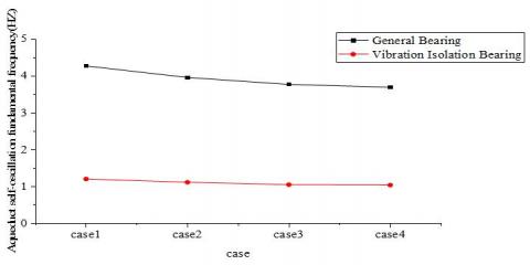
The four cases shown in Table 4 below were selected to analyze and calculate the self-vibration characteristics of the structure of Dongjiacun aqueduct under the support of ordinary basin rubber bearing and high damping vibration isolation bearing, and the self-vibration frequencies and vibration patterns of the aqueduct structure in different water depth cases and different bearings were obtained, and the specific results are shown in Table 5 and Figure 9 below.
Table 4. Selection table of different water depth cases
|
Group |
Brief description of cases |
|
case1 |
Self-weight + no water in the aqueduct trough |
|
case2 |
Self-weight + water level in the aqueduct trough is 1/2 trough water |
|
case3 |
Self-weight + water level in the aqueduct trough is 3/4 trough water |
|
case4 |
Self-weight + water level in the aqueduct trough is full trough water |
Table 5. Comparison of the self-vibration frequency of the aqueduct structure with different supports under different water depth cases
|
|
Base Frequency(Hz) |
Frequency reduction percentage |
|
|
General basin type rubber bearing |
High damping vibration isolation bearing |
||
|
case1 |
4.2700 |
1.2117 |
71.62% |
|
case2 |
3.9583 |
1.1222 |
71.65% |
|
case3 |
3.7709 |
1.0577 |
71.95% |
|
case4 |
3.6944 |
1.0466 |
71.67% |
Figure 9. Self-vibration frequency of the aqueduct structure under different water depth cases with different supports
From Table 5 and Figure 9, we can learn that with the increase of water level in the aqueduct, the vibration frequency of the aqueduct structure decreases, and the theoretical formula of the self-vibration frequency of the structure $\omega=\sqrt{k / m}$ shows that with the increase of the mass of the water body, it will decrease, which is in accordance with the theoretical formula. Compared with the common basin rubber bearing, the self-vibration frequency of the aqueduct structure is reduced significantly after setting the high damping vibration isolation bearing, and the maximum reduction is about 72%, which prolongs the self-vibration period of the structure and reduces the seismic response of the aqueduct structure, and provides a basis for the seismic design of the equivalent type of structure of the aqueduct, and the case 4 is selected as the research object in the next calculation.
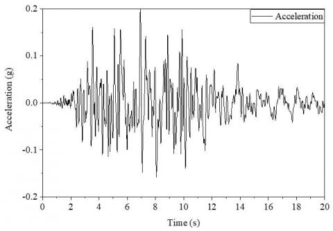
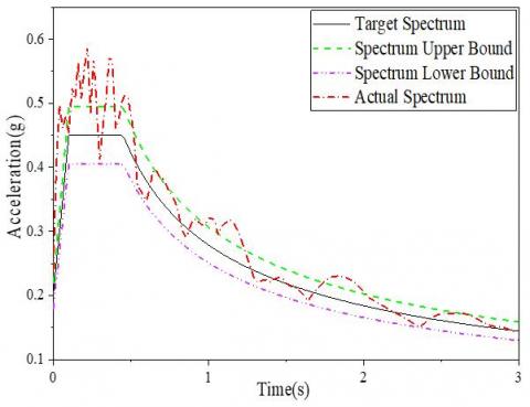
The principle of seismic wave selection is to make the characteristics of the input seismic waves and the building site conditions compatible [10, 11]. The seismic design standards for hydraulic buildings in China specify that three or more groups of seismic waves should be selected to act on the structure separately when the time course analysis is performed on the aqueduct structure. Therefore, a total of three different seismic waves, EL-Centro wave, Kobe wave, and artificial wave, were selected for the seismic response time analysis in this study. EL-Centro wave was widely used as a standard abroad, when the peak horizontal ground acceleration obtained was 341.7 cm/s2 and the duration of the shaking was about 30s [12]. Kobe wave was the seismic wave data recorded during the Great Hanshin. The peak horizontal ground acceleration obtained at that time was 535.8 cm/s2 and the duration of vibration was about 45s. In this study, the first 20 seconds of the representative time range records were selected for analysis and the peak acceleration was adjusted to 0.2g to meet the requirements. In addition, the basic intensity of the project site is 8 degrees, and the site condition is Class II. The peak acceleration of ground shaking with a probability of 10% in the reference period (50 years) is used as the design peak acceleration, the design peak horizontal acceleration is 0.2g, the characteristic period is 0.45s, and the damping ratio is 0.05. An artificial seismic wave with a peak acceleration of 0.2g was synthesized artificially as an input condition for comparative analysis study. As shown in Figure 10 to Figure 12, the comparison between the acceleration time, seismic wave response spectrum and design response spectrum curve is given for each seismic wave.
In Figures 10 to 12, each set of seismic waves is given with the acceleration timescale, the comparison between the acceleration response spectrum and the design response spectrum curve, the Fourier spectrum of the acceleration timescale, and the power spectrum. Analyzing the Fourier spectra of the three sets of seismic acceleration timescales, it can be seen that the low-frequency component of each set of ground shaking acceleration is less and the high-frequency component is more intensive; analyzing the power spectra of the three sets of artificial simulated seismic acceleration timescales, it can be seen that the power of the low-frequency component of the EL-Centro seismic wave is the largest, the power of the low-frequency component of the third set of artificial ground shaking is the second, the power of the low-frequency component of the second set of Kobe seismic wave is The power of the second Kobe seismic wave low-frequency component is the smallest, and the power of the high-frequency component of the three sets of artificial ground shaking is similar. Analyzing the comparison graph between each set of artificial simulated seismic acceleration response spectrum and the design response spectrum curve, it can be seen that all the three sets of ground vibration acceleration time courses meet the requirements of the Seismic Standard.
(a) EL-Centro wave acceleration time course curve
(b) Comparison of EL-Centro wave response spectrum and design response spectrum
Figure 10. Acceleration time course curve of EL-Centro seismic wave with artificially adjusted peak
(a) Kobe wave acceleration time course curve
(b) Comparison of Kobe wave response spectrum and design response spectrum
Figure 11. Acceleration time curve of artificially adjusted peak of Kobe seismic wave
(a) Acceleration time curve
(b) Comparison of EL-Centro wave response spectrum and design response spectrum
Figure 12. Synthetic seismic wave acceleration time curve
A study of the seismic response of a large aqueduct was conducted. To facilitate the discussion of the response of the aqueduct structure, several characteristic points on the transverse interrupted surface of the aqueduct structure were selected to analyze the seismic response in this study. The locations of the feature points are shown in Figure 13 on the right, where point A is located at the top of the side wall, point B is located at the bottom of the side wall, point C is located at the center of the bottom plate of the side channel, point D is located at the top of the middle wall, point E is located at the bottom of the middle wall, point F is located at the center of the bottom plate of the middle channel, and point H is located at one end of the tie rod.
Figure 13. Study feature point selection map
(a) EL-Centro wave
(b) Artificial wave
(c) Kobe wave
Figure 14. Time course of deformation of the vertical wall of the aqueduct structure in the transverse direction under different seismic wave excitation
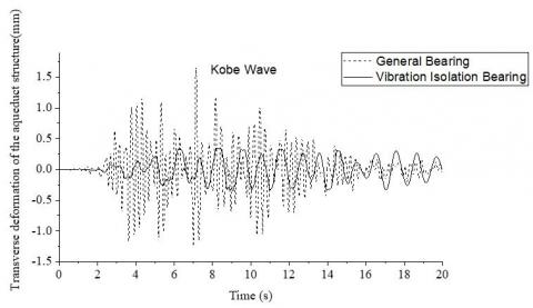
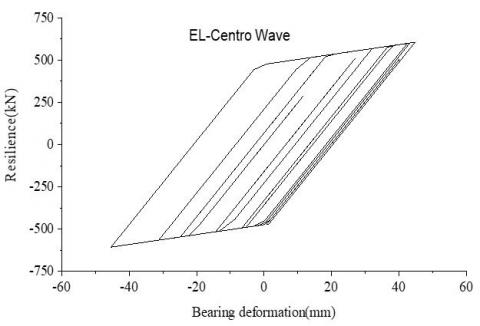
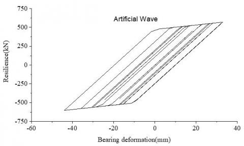
The seismic response of the aqueduct structure under the maximum response condition (condition 4) is calculated and analyzed by input seismic wave meter to explore the effect of different seismic waves on the seismic response of the aqueduct structure. Here, the most representative transverse seismic response of the aqueduct structure is selected for analysis. From its deformation time diagram (see Figure 14 below), it can be seen that the response value of the aqueduct structure under different seismic wave excitation increases or decreases after the adoption of high damping vibration isolation bearings, but the amount of change is relatively smooth compared with that of ordinary basin rubber bearings; from the force-displacement curve of the vibration isolation bearings (see Figure 15 below) we can see that The deformation of the bearing is larger, the hysteresis curve is full, and the effect of energy dissipation and seismic reduction of the bearing is more obvious. It shows that in the process of seismic wave propagation, regardless of the form of seismic wave, when the energy is transferred to the bearing, the high damping vibration isolation bearing can well weaken the energy value that continues to transfer to the upper part of the aqueduct structure, and dissipate a larger part of the energy at the bearing, so that the response of the upper structure is reduced to ensure the safety of the aqueduct structure.
(a) EL-Centro wave
(b) Artificial wave
(c) Kobe wave
Figure 15. Force-displacement curves of seismic isolation bearings under different seismic wave excitations
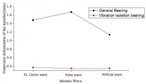
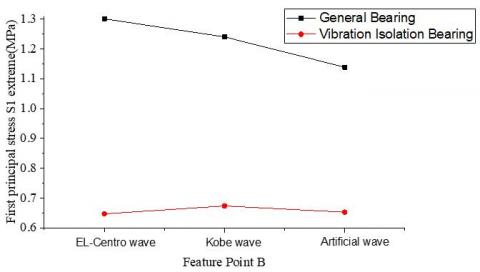
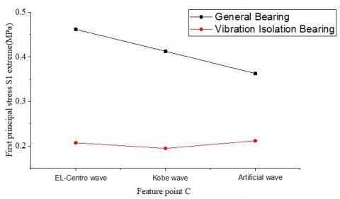
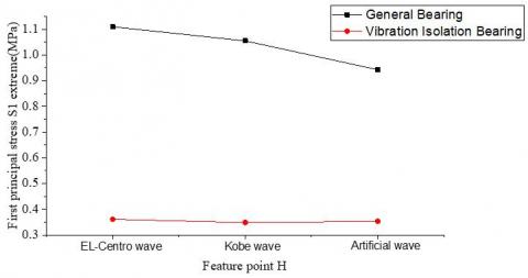
Input different seismic waves, do the time analysis of each characteristic point and select the maximum value for comparative analysis, and give the response of the aqueduct structure under different seismic waves, the results are shown in Figure 16 below. The maximum value of tensile stress at some locations is close to the design value of the concrete tensile strength of the tank body, which is dangerous, while the transverse deformation of the tank structure and the maximum value of tensile stress decrease a lot after adopting high damping vibration isolation bearing, and the maximum value is controlled at about 0.7MPa, which has a large safety reserve and ensures that the tank structure will not be damaged under earthquake.
(a) Transverse deformation of the aqueduct structure
(b) Maximum value of first principal stress at feature point A
(c) Maximum value of first principal stress at feature point B
(d) Maximum value of first principal stress at feature point C
(e) The maximum value of the first principal stress at the feature point D
(f) The maximum value of the first principal stress at the feature point E
(g) The maximum value of the first principal stress at the feature point F
(h) The maximum value of the first principal stress at the feature point H
Figure 16. Maximum seismic response of the aqueduct structure under different seismic wave excitation
The dynamic analysis model of the aqueduct structure is established, and the dynamic characteristics of the large aqueduct structure in Dongjiacun, a water diversion project in central Yunnan, are analyzed under different water depth conditions and different support methods. The calculation results show that the vibration pattern of the aqueduct is mainly based on three vibration patterns, namely, the overall flat motion of the aqueduct structure with the support, the local vibration of the aqueduct wall and the vibration in the cross channel direction, which indicates that the response of the aqueduct structure at the support and at the channel wall is larger and needs to be focused on during the seismic design of the aqueduct; in addition, the vibration frequency of the aqueduct structure decreases with the increase of the depth of the water body in the channel, and the theoretical formula of the self-oscillation frequency of the structure $\omega=\sqrt{k / m}$ shows that As the mass of the water body increases, it will decrease, which is in line with the theoretical formula. Compared with the ordinary basin rubber bearing, the use of high damping vibration isolation bearing makes the self-vibration frequency of the aqueduct structure reduced significantly, and the maximum reduction is about 72%, which prolongs the self-vibration period of the structure and reduces the seismic response of the aqueduct structure. All the table titles and figure captions should be centered, Times New Roman font and 10 pts in size. Just capitalize the first letter of words, phrases and sentences which are included in tables and figures.
Seismic response analysis was conducted for the large aqueduct structure with two different support methods: ordinary basin bearing and high damping vibration isolation bearing, and the effects of different seismic wave random inputs on the aqueduct structure were investigated. When ordinary basin type rubber bearing is used, the seismic response of the aqueduct structure under different seismic wave excitation is different and the response value is large, the maximum value of tensile stress is 1.87MPa at individual position, which is close to the design value of tensile strength of the concrete of the trough body, and there is a certain risk, while the transverse deformation of the aqueduct structure and the maximum value of tensile stress are reduced a lot when high damping vibration isolation bearing is used, and the maximum value is The maximum value is controlled at about 0.7MPa, which has a large safety reserve and ensures that the structure of the aqueduct will not be damaged under the action of earthquake. In addition, after adopting high damping vibration isolation bearing, the response value of the aqueduct structure under different seismic wave excitation is relatively smooth, although there is an increase or decrease, but the change amount is relatively smooth compared with the aqueduct using ordinary basin rubber bearing, which is mainly because, in the process of seismic wave propagation, regardless of the form of seismic wave, when the energy is transferred to the bearing, due to the energy dissipation mechanism of high damping vibration isolation bearing This is mainly because during the propagation of seismic waves, regardless of the form of seismic waves, when the energy is transferred to the bearing, the energy dissipation mechanism of the high damping vibration isolation bearing reduces the response of the upper structure and ensures the safety of the structure of the aqueduct.
[1] Zhao, X. (2004). The research about aqueduct bridge’s vibration reduction technology of SNWTP by the condition of structure-liquid couping. Dissertation. Dalian: Dalian University of Technology.
[2] Zhou, F. (2016). Seismic isolation, energy dissipation and damping and structural control system - an inevitable technical choice to terminate the earthquake disaster in China's urban and rural areas. City and Disaster Reduction, 05: 01-10.
[3] Liu, Y., Dang, K., Dong, J. (2017). Finite element analysis of the aseismicity of a large aqueduct. Soil Dynamics and Earthquake Engineering, 94: 102-108.
[4] Zheng, M., Yang, S., Li, Z. (2011). Numerical simulation of intelligent seismic isolation of large-scale aqueduct. Engineering Journal of Wuhan University, 44(01): 21-25.
[5] Zhang, Y., Hu, X., Hu, X., et al. (2011). Seismic isolation study of large-scale aqueduct with ball bearings. South-to-North Water Transfers and Water Science & Technology, 09(05): 01-05+10.
[6] Liu, X., Wang, J. (2013). Research on the design and application of seismic isolation bearings for the South-North water transfer Shuangcook river crossing. Henan Water Resources and South-to-North Water Diversion, 21: 49-50.
[7] Huang, J., Jiang, H., Pan, C. (2019). Anti-seismic damping technology of prestressed aqueduct project on kirzi river. Journal of Water Resources and Architectural Engineering, 17(02): 124-129.
[8] JT/T842-2012. (2013). High damping seismic isolation rubber bearings for highway bridges. Beijing: People's Traffic Publishing House.
[9] Lou, M., Pan, D., Fan, L. (2003). Effect of vertical artificial boundary on seismic response of soil layer. Journal of Tongji University(Natural Science), 31(07): 757-761.
[10] Wang, Y., Kou, L., Wang, B. (2008). Selection of earthquake wake for earthquake response analysis of aqueduct. Journal of Water Resources and Architectural Engineering, 04: 38-39.
[11] Tan, C. (2004). Study on dynamic property and dynamic responses of arched corrugated metal roof. Beijing: Tsinghua University.
[12] Chen, G. (2007). Dynamic analysis of the fluid-cylindrical digester interaction system. Tianjin: Tianjin University.