Bowen Tian* | Chuanfeng Zheng | Haisong Luo | Junpeng Xun
© 2021 IIETA. This article is published by IIETA and is licensed under the CC BY 4.0 license (http://creativecommons.org/licenses/by/4.0/).
OPEN ACCESS
Targeting at the problem of pavement cracking under long-term load, this study developed a new-type semi-rigid base layer structure based on the CGC (cement stabilized macadam - graded broken stone - cement stabilized macadam) combinations, and used ANSYS to simulate this proposed structure under conditions of different modulus combinations, deflection under different thickness, different vertical strain values on the top surface of roadbed, and different transverse tensile stress values of bottom base layer. The simulation results indicate that, the various mechanical properties of the proposed new structure can well meet the specifications, and the time of crack generation has been slowed down; the use of graded broken stone in the proposed structure has achieved both the purposes of saving construction cost and reducing construction difficulty. By reasonably controlling the CGC structure and modulus, this study has successfully suppressed the generation of reflection cracks, which can provide good theoretical evidence for prolonging the service life of semi-rigid base layer pavement.
asphalt pavement, finite element, reflection cracks, stress distribution, road performance
In China, more than 90% of road pavement structures adopted a semi-rigid base layer structure [1]. During the design process of semi-rigid asphalt base layer pavement, the elastic layered system theory is often used for the design and calculation of road structures. According to related research, the inter-layer bonding state can affect the mechanical response of the pavement structure, poor inter-layer bonding will degrade the performance of the pavement [2]. The semi-rigid asphalt base layer pavement has the properties of small deflection, high rigidity, and weak resistance to deformation, since its bottom base layer often bears a large tensile stress, the pavement can easily reach limit state and crack, and then the cracks will develop into reflection cracks [3]. In China, for most of the semi-rigid base layer pavement, before reaching the service life, its functions have already degraded and the structure has been damaged [4]. Combination analysis of the traditional semi-rigid base layer pavement suggests that it’s more reasonable to control the elastic modulus between 1500-3000Mpa and the thickness below 35cm [5], then, with the increase of the elastic modulus and thickness of the semi-rigid base layer, the change value of each indicator becomes smaller and smaller, so it’s meaningless to blindly increase the elastic modulus and thickness of the semi-rigid base layer. It is known that the graded crushed stone can fully absorb the strain energy released by cracks in the lower layer, in this way, it could suppress the generation of reflection cracks. In view of these facts, we propose a new-type inter-layer combination, the CGC (cement stabilized macadam - graded broken stone - cement stabilized macadam) structure for the target problem in this paper. Then, the ANSYS software is used to simulate the inter-layer state of the CGC structure, such as the stress and strain; through the research, we hope to reduce the thickness and cost as much as possible under the premise of meeting relevant specifications, so that the structure could exert a good role in suppressing reflection cracks.
2.1 Basic assumptions [6]
Following assumptions are usually made for elastic layered systems:
2.2 Structure of asphalt pavement
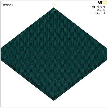
In ANSYS simulation, the influence of boundary size had been minimized as much as possible [7]. Therefore, the constructed semi-rigid asphalt base layer pavement model had a size of 10m×xm×10m, (length, height, and width), the pavement model was divided into 7 layers, from top to bottom, they are: top surface layer, middle surface layer, lower surface layer, top base layer, middle base layer, lower base layer, and soil base layer. Solid185 units were used to build the model, and there’re a total of 81608 units in the model, as shown in Figure 1.
Figure 1. Model of the pavement
2.3 Selection of material parameters
In terms of material selection, all layers in the model were elastic layered structures, the material parameters of each structure layer are listed in Table 1 below.
Table 1. Structure layers and material parameters of the pavement model [8]
|
Structure layer |
Thickness/cm |
Elastic modulus/Mpa |
Poisson’s ratio |
|
Asphalt top surface layer AC-13 |
5 |
1200 |
0.25 |
|
Asphalt middle surface layerAC-16 |
5 |
1450 |
0.25 |
|
Asphalt lower surface layerAC-20 |
10 |
1950 |
0.25 |
|
Cement stabilized macadam |
10/5/10/5 |
800/900/1000/1100/1200 |
0.4 |
|
Graded broken stone |
10/20/20/30 |
300/340/380/420/460 |
0.3 |
|
Cement stabilized macadam |
10/5/10/5 |
800/900/1000/1100/1200 |
0.4 |
|
Soil base |
- |
60 |
0.35 |
2.4 Load selection
The standard axle load of the pavement was indicated by BZZ-100, the value of axle load took 100KN, and the wheel pressure was 0.7Mpa [9, 10]. In this paper, based on the equivalent tire contact area, the shape of the contact area between the wheel and the ground was simplified into a rectangle with a length of 0.21m and a width of 0.167m, the distance between the centers of two wheels was 1.3m, see Figure 2.
Figure 2. Shape of the contact area between wheel and ground
2.5 Boundary conditions
To simulate real pavement conditions, it’s necessary to set boundary conditions for the pavement model. In the Y direction, namely the structure depth direction, the bottom position was fixed; there’s no displacement on the left and right sides of X direction, namely the driving direction; and there’s no Z-direction displacement on both sides of the cross section.
3.1 Vertical strain of the top surface of roadbed
The allowable vertical compressive strain on the top surface of roadbed was calculated by Formula 1.
[εz]=1.25×10⁴-0.1β (kT3Ne4)-0.21 (1)
where,
[εz] is the allowable vertical compressive strain on the top surface of roadbed (10-6);
β is the reliability index, according to the highway grade, its value took 1.28 in this paper;
Ne4 is the cumulative number of equivalent design axle loads on the designed lane within the designed service life, its value was 12000000;
kT3 is the temperature adjustment coefficient, its value took 1.129;
After calculation, it’s obtained that εz =0.29595×10⁻³.
3.2 Transverse tensile stress of the bottom base layer
Table 2. Allowable tensile stress of structure layers
|
Structure layer |
Allowable tensile stress/Mpa |
|
Asphalt pavement layer |
0.465 |
|
Base layer |
0.323 |
|
Bottom base layer |
0.087 |
The HPDS pavement design software allows users to design highways of different grades according to the latest highway design specifications, the purpose of this software is to alleviate the workload of constructors, reduce errors in manual calculations, and make the various grades of highways be more in line with national standards. After inputting the structure layers of the pavement and their elastic modulus values into the software, the output calculated allowable tensile stress of the bottom base layer was 0.087 MPa (Table 2).
4.1 Deflection value
Deflection is caused by the deformation of each structure layer of the pavement when the road surface is subject to a load, it can reflect the load-bearing capacity of each structure layer, to a certain extent, it can also reflect the use state of the road. A too-large deflection value indicates that the load-bearing capacity of each structure layer is insufficient, and the road’s ability to resist damages will weaken gradually, under the comprehensive effects of external factors such as traffic loads, and climate and environment conditions, a series of diseases will occur to the road. Therefore, deflection is a very important indicator for studying the different pavement structures [11], and the deflection values of pavements with different thickness and modulus obtained through simulation are given in Table 3.
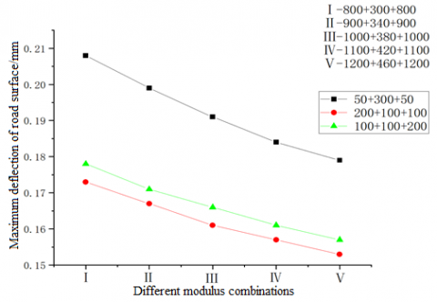
Figure 3. Deflection of the pavement under conditions of different modulus combinations and a base layer thickness of 300 mm
Figure 4. Deflection of the pavement under conditions of different modulus combinations and a base layer thickness of 400 mm
Figure 5. Simulation of the deflection of 100+100+100 pavement
Table 3. Deflection of pavements with different structures and modulus values
|
Base layer structure |
Different modulus combinations/Mpa |
Maximum deflection of road surface/mm |
|
100+100+100 |
800+300+800 |
0.172 |
|
900+340+900 |
0.165 |
|
|
1000+380+1000 |
0.160 |
|
|
1100+420+1100 |
0.156 |
|
|
1200+460+1200 |
0.152 |
|
|
50+200+50 |
800+300+800 |
0.191 |
|
900+340+900 |
0.183 |
|
|
1000+380+1000 |
0.177 |
|
|
1100+420+1100 |
0.171 |
|
|
1200+460+1200 |
0.167 |
|
|
100+200+100 |
800+300+800 |
0.191 |
|
900+340+900 |
0.183 |
|
|
1000+380+1000 |
0.176 |
|
|
1100+420+1100 |
0.171 |
|
|
1200+460+1200 |
0.166 |
|
|
50+300+50 |
800+300+800 |
0.208 |
|
900+340+900 |
0.199 |
|
|
1000+380+1000 |
0.191 |
|
|
1100+420+1100 |
0.184 |
|
|
1200+460+1200 |
0.179 |
|
|
200+100+100 |
800+300+800 |
0.173 |
|
900+340+900 |
0.167 |
|
|
1000+380+1000 |
0.161 |
|
|
1100+420+1100 |
0.157 |
|
|
1200+460+1200 |
0.153 |
|
|
100+100+200 |
800+300+800 |
0.178 |
|
900+340+900 |
0.171 |
|
|
1000+380+1000 |
0.166 |
|
|
1100+420+1100 |
0.161 |
|
|
1200+460+1200 |
0.157 |
The deflection of different base layer structures with different elastic modulus values was simulated using the constructed model, and the obtained values showed that, under each structure, the displacement of road surface had met the specifications. Under the condition that the thickness of the base layer was 300mm, the pavement deflection values of different base layer structures had all met the specifications (Figure 3, Figure 4). With the increase of modulus, the pavement deflection values decreased gradually (Figure 5). In case of the 50+200+50 base layer structure, when the modulus combination changed from 800+300+800 to 1200+460+1200, the maximum deflection of the pavement was 0.191mm, the minimum deflection of the pavement was 0.167mm, the deflection value of the pavement had reduced by 12.6%. In case of the 100+100+100 base layer structure, when the modulus combination changed from 800+300+800 to 1200+460+1200, the maximum deflection of the pavement was 0.172mm, the minimum deflection of the pavement was 0.152mm, the deflection value of the pavement had reduced by 11.6%. After analyzing the data, it’s found that under a same thickness, the thicker the cement stabilized macadam, the smaller the pavement deflection value. Under the condition that the thickness of the base layer was 400mm, the pavement deflection of different base layer structures had all met the specifications. With the increase of modulus, the pavement deflection values decreased gradually. In case of the 50+300+50 base layer structure, when the modulus combination changed from 800+300+800 to 1200+460+1200, the maximum deflection of the pavement was 0.208mm, the minimum deflection of the pavement was 0.179mm, the deflection value of the pavement had reduced by 13.9%. In case of the 200+100+100 base layer structure, when the modulus combination changed from 800+300+800 to 1200+460+1200, the maximum deflection of the pavement was 0.173mm, the minimum deflection of the pavement was 0.153mm, the deflection value of the pavement had reduced by 11.6%. In case of the 100+100+200 base layer structure, when the modulus combination changed from 800+300+800 to 1200+460+1200, the maximum deflection of the pavement was 0.178mm, the minimum deflection of the pavement was 0.157mm, the deflection value of the pavement had reduced by 11.8%. After analyzing the data, it’s found that under a same thickness, the thicker the cement stabilized macadam, the smaller the pavement deflection value. In case of a same base layer structure, if the cement stabilized macadam is placed in the bottom base layer, the deflection value of the pavement will increase slightly.
4.2 Tensile stress at the bottom of bottom base layer
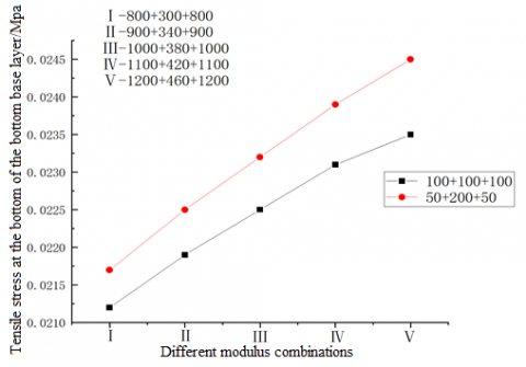
Figure 6. Tensile stress at the bottom of bottom base layer under the conditions of different modulus combinations and a base layer thickness of 300 mm
Figure 7. Tensile stress at the bottom of bottom base layer under the conditions of different modulus combinations and a base layer thickness of 400 mm
When the tensile stress at the bottom of bottom base layer is greater than the allowable tensile stress at the bottom of the base layer, cracks will appear in the base layer, and to a certain extent, the growth speed the cracks spreading to the surface layer is determined by the thickness of the base layer, namely the structure combination of the base layer (Figure 6, Figure 7). The too-thick base layer will greatly increase the construction cost of the pavement, during construction, it’ll be difficult to compact the pavement, moreover, after putting into real use, the pavement is prone to wheel rutting and other damages, which will seriously affect the quality of the pavement (Figure 8). If the thickness of the base layer is too small, the bottom layer stress is not obvious, therefore, a good choice of base layer structure combination can prevent the generation of cracks. According to the results of finite element analysis shown below, it’s obtained that the base layers of different modulus combinations had also met the specifications of tensile stress at the bottom of base layer in Table 4.
Figure 8. Tensile stress at the bottom of bottom base layer of the 100+100+100 pavement
Table 4. Vertical compressive strain on the top surface of roadbed with different base structure types
|
Base layer structure |
Different modulus combinations/Mpa |
Tensile stress at the bottom of bottom base layer/Mpa |
|
100+100+100 |
800+300+800 |
0.021188 |
|
900+340+900 |
0.021894 |
|
|
1000+380+1000 |
0.022511 |
|
|
1100+420+1100 |
0.023057 |
|
|
1200+460+1200 |
0.023545 |
|
|
50+200+50 |
800+300+800 |
0.02167 |
|
900+340+900 |
0.025509 |
|
|
1000+380+1000 |
0.023249 |
|
|
1100+420+1100 |
0.023908 |
|
|
1200+460+1200 |
0.024502 |
|
|
100+200+100 |
800+300+800 |
0.015931 |
|
900+340+900 |
0.016371 |
|
|
1000+380+1000 |
0.016755 |
|
|
1100+420+1100 |
0.017094 |
|
|
1200+460+1200 |
0.017396 |
|
|
50+300+50 |
800+300+800 |
0.016455 |
|
900+340+900 |
0.016957 |
|
|
1000+380+1000 |
0.017396 |
|
|
1100+420+1100 |
0.017784 |
|
|
1200+460+1200 |
0.01813 |
|
|
200+100+100 |
800+300+800 |
0.016358 |
|
900+340+900 |
0.016742 |
|
|
1000+380+1000 |
0.017073 |
|
|
1100+420+1100 |
0.017363 |
|
|
1200+460+1200 |
0.017619 |
|
|
100+100+200 |
800+300+800 |
0.017111 |
|
900+340+900 |
0.017525 |
|
|
1000+380+1000 |
0.017882 |
|
|
1100+420+1100 |
0.018194 |
|
|
1200+460+1200 |
0.018471 |
With the help of the constructed model, the tensile stress at the bottom of bottom base layer under different base layer structures and different elastic modulus values were simulated, and the results showed that for each structure type, the tensile stress at the bottom of bottom base layer had all met the specifications. After analyzing the data, it’s concluded that, under a same thickness, the thicker the cement stabilized macadam, the smaller the tensile stress at the bottom of the bottom base layer of the pavement. The thicker the graded crushed stone, the higher the growth rate of tensile stress at the bottom of the bottom base layer. Under the condition of a same type of base layer structure, if the cement stabilized macadam is placed in the bottom base layer, the tensile stress at the bottom of the bottom base layer of the pavement will increase slightly.
4.3 Vertical compressive strain on the top surface of roadbed
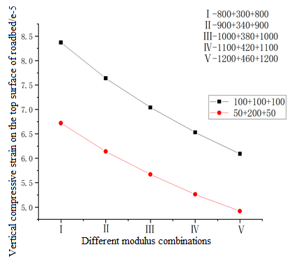
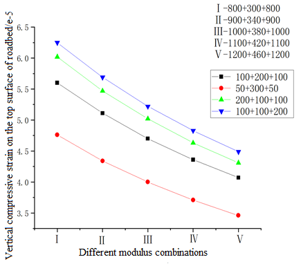
Figure 9. Vertical compressive strain on the top surface of roadbed under the conditions of different modulus combinations and a base layer thickness of 300 mm
Figure 10. Vertical compressive strain on the top surface of roadbed under the conditions of different modulus combinations and a base layer thickness of 400 mm
The obtained values showed that, under each structure, the vertical compressive strain on the top surface of roadbed had all met the specifications. After analyzing the data, it’s concluded that, under a same thickness, the thicker the cement stabilized macadam, the smaller the vertical compressive strain on the top surface of roadbed (Figure 9, Figure 10). The thicker the graded broken stone used in the pavement, the lower the growth rate of vertical compressive strain on the top surface of roadbed. Under the condition of a same type of base layer structure (Figure 11), if the cement stabilized macadam is placed in the bottom base layer, the vertical compressive strain on the top surface of roadbed will increase slightly in Table 5.
Table 5. Vertical compressive strain on the top surface of roadbed under different base layer structures
|
Base layer structure |
Different modulus combinations/Mpa |
Vertical compressive strain on the top surface of roadbed |
|
100+100+100 |
800+300+800 |
-8.37e-5 |
|
900+340+900 |
-7.64e-5 |
|
|
1000+380+1000 |
-7.04e-5 |
|
|
1100+420+1100 |
-6.53e-5 |
|
|
1200+460+1200 |
-6.09e-5 |
|
|
50+200+50 |
800+300+800 |
-6.72e-5 |
|
900+340+900 |
-6.14e-5 |
|
|
1000+380+1000 |
-5.67e-5 |
|
|
1100+420+1100 |
-5.26e-5 |
|
|
1200+460+1200 |
-4.92e-5 |
|
|
100+200+100 |
800+300+800 |
-5.6e-5 |
|
900+340+900 |
-5.11e-5 |
|
|
1000+380+1000 |
-4.7e-5 |
|
|
1100+420+1100 |
-4.36e-5 |
|
|
1200+460+1200 |
-4.07e-5 |
|
|
50+300+50 |
800+300+800 |
-4.76e-5 |
|
900+340+900 |
-4.34e-5 |
|
|
1000+380+1000 |
-4.0e-5 |
|
|
1100+420+1100 |
-3.71e-5 |
|
|
1200+460+1200 |
-3.46e-5 |
|
|
200+100+100 |
800+300+800 |
-6.02e-5 |
|
900+340+900 |
--5.47e-5 |
|
|
1000+380+1000 |
-5.02e-5 |
|
|
1100+420+1100 |
-4.63e-5 |
|
|
1200+460+1200 |
-4.31e-5 |
|
|
100+100+200 |
800+300+800 |
-6.25e-5 |
|
900+340+900 |
-5.69e-5 |
|
|
1000+380+1000 |
-5.22e-5 |
|
|
1100+420+1100 |
-4.83e-5 |
|
|
1200+460+1200 |
-4.49e-5 |
Figure 11. Vertical compressive strain on the top surface of roadbed of the 100+100+100 pavement
By conducting numerical simulation on base layer structures of different thickness and modulus combinations, this paper obtained a new-type pavement structure, the CGC structure. Simulation data showed that, the proposed structure had met relevant specifications in terms of deflection value, tensile stress at the bottom of bottom base layer, and vertical strain on the top surface of roadbed. In engineering projects in the future, by reasonably controlling the CGC structure and modulus of the pavement, the design ideas of suppressing crack generation and optimizing pavement structure could be realized, which has a certain reference value for the structure design of asphalt pavement.
[1] Assogba, O.C., Sun, Z., Tan, Y., Nonde, L., Bin, Z. (2020). Finite-element simulation of instrumented asphalt pavement response under moving vehicular load. International Journal of Geomechanics, 20(3): 04020006. https://doi.org/10.1061/(ASCE)GM.1943-5622.0001616
[2] Zhao, B.W. (2020). Mechanical response analysis of semi -rigid base asphalt pavement based on different bonding conditions. Northern Communications, 11: 66-69. https://doi.org/10.15996/j.cnki.bfjt.2020.11.017
[3] Zhao, J. (2020). Comparative analysis of asphalt pavement structure between semi-rigid base and flexible base. China Housing Facilities, 6: 97, 112.
[4] Lv, S., Yuan, J., Peng, X., Cabrera, M.B., Liu, H., Luo, X., You, L. (2021). Standardization to evaluate the lasting capacity of rubberized asphalt mixtures with different testing approaches. Construction and Building Materials, 269: 121341. https://doi.org/10.1016/j.conbuildmat.2020.121341
[5] Zhang, R.Z., Ling, T.Q., Yuan, M., Ning, H.Y. (2011). Influence of Asphalt Semi-rigid Base Modules on Pavement Structural Stress. Journal of Chongqing Jiaotong University (Natural Science), 30(4): 755-758, 863.
[6] Si, W.B. (2017). Analysis of Asphalt Pavement Structure with Combined Base Course Based on Finite Element. Chongqing Jiaotong University.
[7] Wang, X., Ma, X. (2020). Responses of semi-rigid base asphalt pavement with interlayer contact bonding model. Advances in Civil Engineering, 2020: 8841139. https://doi.org/10.1155/2020/8841139
[8] Luo, Y.S. (2016). The influence analysis of structural parameters on the mechanical behavior of asphalt pavement. Shanxi Science & Technology of Communications, 3: 26-28.
[9] Hu, X.D., Sun, L.J. (2005). Measuring tire ground pressure distribution of heavy vehicle. Journal-Tongji University, 33(11): 1443.
[10] Dong, H.B. (2012). Indoor Evaluation Test Research on Top-down Cracks of Asphalt Pavement. Changan University.
[11] Wang, G., Zhang. Y.B. (2020). Finite Element Analysis of Asphalt Pavement Structure with Semi-rigid Base Under Overload. Journal of Wuhan University of Technology(Transportation Science & Engineering), 44(3): 579-583. https://doi.org/10.3963/j.issn.2095-3844.2020.03.035