Chao Zhang![]() | Lei Yu
| Lei Yu![]() | Xiaoqing Hu
| Xiaoqing Hu![]() | Qian Wu
| Qian Wu![]() | Ju Wang
| Ju Wang![]() | Zhuo Xu*
| Zhuo Xu*![]()
© 2023 IIETA. This article is published by IIETA and is licensed under the CC BY 4.0 license (http://creativecommons.org/licenses/by/4.0/).
OPEN ACCESS
The conventional method to locate acupuncture points (acupoints) on human body requires the massagists to have rich experience and skillful performance, and the learning cost is always high. The visual positioning technology of massage acupoints based on image registration can lower the technical difficulty, thereby allowing more people to enjoy and benefit from massage therapy. However, existing algorithms for this technology generally have a series of shortcomings including the unstable matching results, the inaccurate image registration effect, and the unsatisfactory results in case of obvious local deformation or occlusion. In view of these matters, this paper studied a novel visual positioning algorithm for acupoints based on image registration. At first, an Image Acupoints Positioning algorithm was proposed based on Convolution Neural Network (CNN-based IAP algorithm), the algorithm can combine the prior information of acupoint positions in visual images with 3D CNN, which has a stronger feature expression ability, and maintain high positioning accuracy under unfavorable conditions such as image noise, illumination change, or occlusion. Then, based on the structure of Fully Convolutional Network (FCN), a multi-scale parallel FCN was constructed, which has introduced the techniques of multi-scale parallel downsampling, spatial pyramid of dilated convolutions, adaptive channel attention mechanism, direction perception, and upsampling, intending to improve the model’s performance in non-rigid registration of the visual images of massage acupoints. At last, the validity of the proposed model was verified by experimental results.
image registration; massage acupoints; visual positioning; convolution neural network (CNN)
Health issues are always a major concern for most people and massage has becoming an increasingly popular therapy as it is natural and has no side effect [1-3]. Acupoint massage is an important part of traditional Chinese medicine therapy, and by stimulating certain acupoints, some curative effects, such as conditioning the human body, relieving fatigue and strain, or curing diseases, could be achieved [4-11]. Apparently, the accurate positioning of acupoints is related to the effect of massage therapy. The conventional method to locate acupoints on human body requires the massagists to have rich experience and skillful performance, and the learning cost is always high [12-16]. The visual positioning technology of massage acupoints based on image registration can lower the technical difficulty, thereby allowing more people to enjoy and benefit from massage therapy, thus it is of utterly importance to research the visual positioning of massage acupoints based on image registration [17-21], and this research can spur technical advancement in fields such as computer vision, image processing, and biomedical engineering, enlightening new sparkles in research ideas and methods.
Lin and Yi [22] considered an automatic human acupoints recognition system based on computer binocular vision technology for the purpose of accurately locating and recognizing acupoints on human body during medical treatment, their method adopted the binocular vision technology to collect images of human body limbs and attain 3D coordinates in space; then to verify their method, the positioning errors of each marked point calculated by the binocular vision technology and measured by a 3D coordinate measuring instrument were compared, the results proved that the proposed system can help therapists locate and recognize acupoints and it could meet clinical application requirements. Wei et al. [23] pointed out that finding and positioning acupoints precisely is one critical factor for massage robots, and they proposed a modeling method for robot positioning based on least squares. In their work, a knowledge consultation mechanism was set for the calculation of acupoint positions as a robot would need feature points of the foot to be massaged to divide and fit foot contour sampling data into piece-wise curves. Since the robots are model-free, Q-learning was adopted to optimize robot positioning, and robots could calculate the approximate positions of acupoints through the prediction model, and meanwhile performing online adjustments to get the accurate positions through Q-learning. These strategies enable robots to automatically search and position the pelma acupoint with little real-time computation and storage, and the idea of this paper provides a clue for Chinese medical standardization. Hao and Han [24] introduced the current research progress of Acupoints positioning and tracking technology (APTT), including the APTT based on vision, based on template matching, and based on Back-Propagation neural network, also, the drawbacks of existing techniques and the prospect of APTT were discussed in their paper.
Existing image registration-based IAP algorithms can be divided into three major categories: those based on feature points, those based on regions, and those based on deep learning, wherein feature point extraction and matching are easily affected by image noise, illumination change, and occlusion, leading to unstable matching results; and for elastic biological tissues such as muscle and skin, the feature points may deform, lowering image registration precision. Besides, those region-based methods need a long computation time since their computation load is large, and such load will be particularly high when there are obvious local deformations or occlusions, and a longer computation time is required. As for the third type, those based on deep learning, massive tag data is required for training, but in the acupoint massage scenario, it’s difficult to acquire so large amounts of data, and moreover, these deep learning-based methods also need high computational resources and may not be current enough. So, to overcome the shortcomings of above-said algorithms, this paper studied a novel IAP algorithm based on image registration. In the second chapter, an CNN-based IAP algorithm was proposed which can combine the prior information of acupoint positions in visual images with 3D CNN and maintain high positioning accuracy under unfavorable conditions such as image noise, illumination change, or occlusion. In the third chapter, based on the structure of FCN, a multi-scale parallel FCN was constructed, with multi-scale parallel downsampling, spatial pyramid of dilated convolutions, adaptive channel attention mechanism, direction perception, and upsampling introduced, intending to improve the model’s performance in non-rigid registration of the visual images of massage acupoints. At last, the validity of the proposed model was verified by experimental results.
When researching positioning algorithms for visual images of massage acupoints, the prior information of inherent acupoint positions in the image is helpful for positioning, but it has seldom been applied in CNN-based positioning algorithms. In order to make the model focus more on the features of acupoint positions and improve the positioning accuracy, this paper proposed a novel IAP algorithm based on CNN that combines the prior information of acupoint positions in visual images with 3D CNN, which has a stronger feature expression ability, and gives highly accurate positioning results under unfavorable conditions such as image noise, illumination change, or occlusion.
Patch-based prediction strategy could be adopted to realize the combination of the said prior information and 3D CNN, namely to crop a small patch from a local area of the acupoint image, and this local area needs to contain the target acupoint and its surrounding area, then the cropped patch is input into to CNN for feature extraction, and the relative position between the acupoint and the patch is predicted according to the extracted features. Since the coordinates of the cropped patch are known, the absolute position of the target acupoint in the image could be calculated based on the prediction results of the relative position. Through above operations, the model could focus on the target acupoint and its surrounding area, in this way, the interference of the background to the positioning task could be reduced, and the positioning accuracy could be improved; in the meantime, it could flexibly cope with different scales, angles, and deformations with high adaptability.
There are individual differences between people, and such differences would accumulate and enlarge as the distance in the acupoint image increases, resulting in a lower prediction accuracy. If the patch is far from the target acupoint, then it’s likely that the content of the target acupoint is not contained in the patch, so it’s impossible to accurately predict the shape and size of the target acupoint through the extracted features. To fully consider situations at different distances from the target acupoint so that the training process is more comprehensive and the prediction is more accurate, this paper proposed a multi-density sampling strategy, that is, to sample in areas at different distances from the target acupoint with different densities. Such multi-density sampling strategy enables the network to prediction tasks of different distances, it could enhance the generalization ability of the network, increase the diversity of training samples, and reduce the over-fitting risk of the model.
The prediction tasks of patches closer to the target acupoint are simpler and the prediction of farther patches is more difficult. If patch-based loudness prediction at different distances is to be realized in the true sense, then different loss functions for long distance, medium distance and short distance need to be set and adopted based on multi-density sampling, this is because the different loss functions enable the network to make effective predictions at different distances, and the overall prediction performance of the network could be enhanced.
In the model output, besides a 6-dimensional 3D box coordinate is output for each acupoint, a binary variable ind is also output for each acupoint, which is used to judge whether the sampled patch is within the predictable region of the corresponding acupoint or not. When the patch is within the predictable range, the tag of ind is 1, indicating that the model can predict the acupoints in this patch; when the patch is not within the predictable range, the tag of ind is 0, indicating that the model can not make effective predictions on acupoints in this patch. As mentioned above, different loss functions need to be set to enable the network to make effective predictions at different distances, these loss functions judge the region type of the patch according to the value of ind, and then adjust the learning strategy of the network based on the region type. In this way, the network can better learn how to make effective acupoint predictions at various distances.
For patches at long distances from the sampling region of each acupoint, only a binary variable MSE needs to be considered during training. Assuming: t represents the number of sample points; ycz represents the predicted value, zsz represents the true value, then the following formula gives the loss function for long distance:
$\operatorname{Loss}_Y=\frac{1}{t} \sum_{i=1}^t\left(y c z_i-\overline{z s z_i}\right)^2$ (1)
For patches at medium distances from the sampling region of each acupoint, both the center point offset prediction of the target acupoint and the binary variable need to be considered during training, that is, the MSE loss functions of the two are calculated and superimposed separately. Assuming: ai, bi, ci respectively represent the predicted offset in the three coordinate axis directions between the patch center and the target acupoint center; a¯i, b¯i, c¯i respectively represent the corresponding true offset values, then the following formula gives the loss function for medium distance:
$\begin{align} & Los{{s}_{Z}}=\frac{1}{t}\sum\limits_{i=1}^{t}{{{\left( yc{{z}_{i}}-{{\overline{zsz}}_{i}} \right)}^{2}}} \\ & +\frac{1}{3t}\sum\limits_{i=1}^{t}{\left[ {{\left( {{a}_{i}}-{{a}_{i}} \right)}^{2}}+{{\left( {{b}_{i}}-{{{\bar{b}}}_{i}} \right)}^{2}}+{{\left( {{c}_{i}}-{{{\bar{c}}}_{i}} \right)}^{2}} \right]} \\\end{align}$ (2)
In practice, whether the box in the acupoint image is an axially aligned one can be represented by a 6-dimensional vector (a, b, c, g, e, f), specifically, it contains the center point coordinates (a, b, c) and lengths (g, e, f) in three orthogonal directions; assuming hz1 and hz2 represent two boxes, then the following formula calculates their intersection over union (IOU):
$IOU=\frac{hzj\cap hz2}{hzj\cup hz2}$ (3)
As a result, the formula for the IOU loss function can be derived:
$Los{{s}_{IOU}}=1-IOU$ (4)
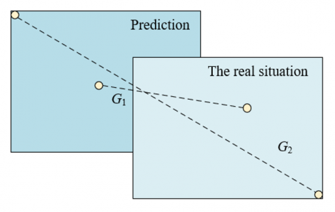
Figure 1. G1 and G2
To allow loss functions to continue to operate even in cases there is no intersection between two boxes, the above formula needs to be updated to the formula below. Assuming: G1 represents the distance of center points of the prediction box and the box of real situation (target box); G2 represents the length of the diagonal line of the minimum enclosing rectangle enclosed by the prediction box and the target box, see Figure 1 for details, then there is:
$Los{{s}_{IOU}}=1-IOU+\frac{G_{1}^{2}}{G_{2}^{2}}$ (5)
Based on above formula, a term of length-width ratio is added, and the loss function formula is further updated to:
$Loss_{IOU}^{*}=1-IOU+\frac{G_{1}^{2}}{G_{2}^{2}}+\left( {{\beta }_{1}}{{u}_{1}}+{{\beta }_{2}}{{u}_{2}} \right)$ (6)
Assuming: fkl, ekl, gkl respectively represent the length of the target acupoint box on the three orthogonal axes; f, e, g respectively represent the length of the prediction box on the three orthogonal axes, then the specific parameters of the above formula can be calculated by the following formulas:
$u_1=\frac{4}{\pi^2}\left(\arctan \frac{f^{k d}}{e^{k d}}-\arctan \frac{f}{e}\right)^2$ (7)
${{u}_{2}}=\frac{4}{{{\pi }^{2}}}{{\left( \arctan \frac{{{f}^{kl}}}{{{g}^{kl}}}-\arctan \frac{f}{g} \right)}^{2}}$ (8)
${{\beta }_{1}}=\frac{{{u}_{1}}}{1-IOU+{{u}_{1}}}$ (9)
${{\beta }_{2}}=\frac{{{u}_{2}}}{1-IOU+{{u}_{2}}}$ (10)
For patches sampled at short distances from a certain acupoint, the final loss function is:
$Loss=\frac{1}{t}\sum\limits_{i=1}^{t}{{{\left( ys{{z}_{i}}-{{\overline{zsz}}_{i}} \right)}^{2}}+Loss_{IOU}^{*}}$ (11)
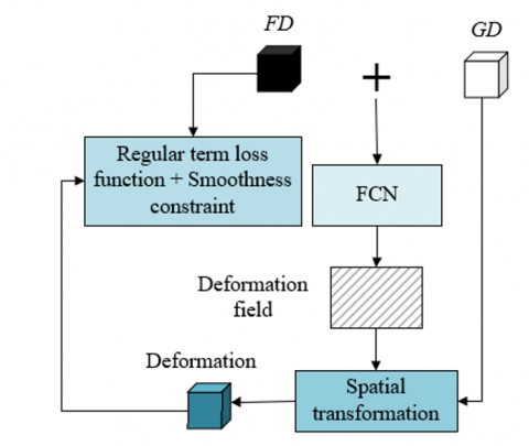
The traditional method of attaining the optimal transformation parameters through iterations of objective deformation function has a slow speed and can not meet real-time requirements, while the deep learning-based visual image registration algorithm that requires supervision information has a poor performance in registration of acupoint images with large deformations, regarding these shortcomings, this paper built a multi-scale parallel FCN to perform non-rigid registration on acupoint images. For the purpose of reducing the need for supervision information, this paper built an end-to-end registration model based on FCN algorithm; in order to capture feature information of different scales and improve the adaptability of the model to acupoint images with large deformations, a multi-scale parallel down-sampling module was set; moreover, a spatial pyramid of dilated convolutions was set to enlarge receptive field and better capture local and global information of the images; and an adaptive channel attention module was set to strengthen the model’s feature perception and expression abilities. Still, for the sake of restraining convergence and enabling the deep network model to learn more suitable deformation parameters, a loss function was set based on image dissimilarity metrics and regularization function. Figure 2 shows the flow of the registration algorithm.
Through above design, the trained deep network model only needs one calculation to predict the deformed image, and it meets real-time requirements. Moreover, through techniques of multi-scale parallel downsampling, spatial pyramid of dilated convolutions, and adaptive channel attention, the model’s feature expression ability could be enhanced and the registration accuracy could be improved.
Figure 3 shows a diagram of the multi-scale parallel downsampling module. After going through the processing of multi-scale parallel downsampling, the feature images contain many information of multiple scales which can hardly be processed by ordinary convolution at a time. In the meantime, the concentrated features of pooling layer used during downsampling might lead to partial information loss, thereby affecting the registration effect. The pyramid dilated convolution module uses dilated convolutions with different dilation factors to process multi-scale information. These dilated convolutions with different dilation factors have receptive fields with varying sizes, enabling the network to capture feature information of different scales simultaneously. Assuming: km represents the m-th layer of receptive field; km-1 represents the m-1-th layer of receptive field; SIi represents the step of the i-th layer of convolution or pooling; r represents the size of convolution kernel, then the following formula gives the method for calculating the receptive field:
${{k}_{m}}={{k}_{m+1}}+\left( r+1 \right)*\prod\limits_{i=1}^{m-1}{S{{I}_{i}}}$ (12)
Figure 2. Flow of registration algorithm
Figure 3. Diagram of multi-scale parallel downsampling module
Figure 4 gives a diagram showing the attenuation of the spatial pyramid of dilated convolutions. After going through the two-step processing of multi-scale parallel sampling and pyramid dilated convolution, the number of acupoint images of with large deformation features is significantly higher than that with minor deformation features. The improvement of registration accuracy requires to extract more minor deformation features. The adaptive channel attention module can carry out adaptive channel attention calculations on feature images and realize adaptive weighting on minor deformation features of different channels, thereby enhancing the expression ability of these minor deformation features in the model and improving the non-rigid registration effect of acupoint images.
Figure 4. Attenuation of the spatial pyramid of dilated convolutions
Since the FCN used in this paper is relatively shallow and it’s difficult to fully exert the powerful channel screening function of channel attention mechanism, in this study, a trainable soft threshold with image similarity as the operator was set for the channel attention mechanism, which can assist the model in adaptively screening out the feature images that have a greater impact on the registration effect. By discarding feature images that are not of interest, the model can focus more on feature images that contribute more to the registration effect, in this way, model performance and registration accuracy could be improved. Specifically, when a feature image is judged to be of minor deformation, its weight is increased r(r>1); if it is judged to be of large deformation, its weight is decreased r-1(r>1), that is:
$scal{{e}^{*}}=\left\{ \begin{align} & r*scale,xi<\varepsilon \\ & (r-1)*scale,xi\ge \varepsilon \\\end{align} \right.$ (13)
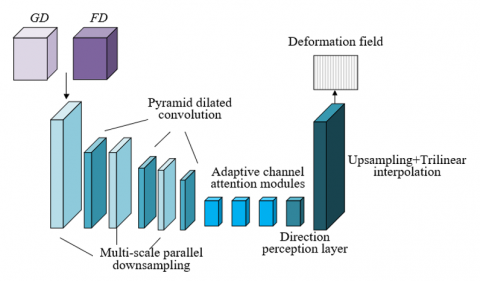
Figure 5. Structure of the constructed neural network
This paper constructed the multi-scale parallel FCN based on the structure of ordinary FCN, and introduced multi-scale parallel downsampling, pyramid dilated convolution, adaptive channel attention, direction perception, and upsampling to improve the non-rigid registration performance of acupoint images. Figure 5 shows the structure of the constructed neural network. Wherein, the multi-scale parallel downsampling module attains feature images at different scales by reducing image size, thereby realizing extraction of features of multiple scales. The pyramid dilated convolution module further enhances the feature perception ability based on extracted multi-scale features. The adaptive channel attention module introduces attention mechanism into feature processing to highlight important features and improve model performance. The direction perception layer and the upsampling layer use a 1×1×1 convolution layer to replace the fully-connected layer of CNN to perform linear prediction on the offset of pixels in X, Y and Z directions, also, the upsampling layer restores the resolution of original images to attain a dense vector deformation field.
The primary objective of image registration is to find a spatial transform that can maximize the pixel-by-pixel relationship between a floating image FD and a fixed image GD. The loss function of the proposed model includes two parts: image dissimilarity metric and regular term. The main reason is that by measuring the differences between the two images, the loss function can guide the network to find a spatial transform that maximizes the pixel-by-pixel relationship between the floating image and the fixed image. Through the image dissimilarity metric, the loss function directly reflects the image registration effect, which can assist the network to better learn the correspondence between images. Introducing regular terms makes the attained dense displacement vector field have a spatial smoothness constraint, which not only ensures that the deformations are reasonable, but also avoids too complicated or unnatural deformations, thus the quality of registration results could be improved.
Assuming: LOSS(·) represents the loss function, which consists of image dissimilarity metric FI(·) and regular term SI(·), δ represents the dense deformation vector field, λ represents the coefficient of regular term, then there is:
$LOSS\left( FD,GD,\delta \right)=FI\left( FD,\delta \left( GD \right) \right)+\chi SI\left( \phi \right)$ (14)
In medical image registration, the various dissimilarity metrics based on image intensity mean variance, cross correlation, or mutual information are greatly affected by image intensity distribution and contrast, so their robustness is generally unsatisfactory. Compared with global cross-correlation methods, taking the local cross-correlation function as the loss function of image dissimilarities can exhibit better performance in capturing local image features. By minimizing the dissimilarity metric, the network can learn the spatial transform that makes the local areas of two images as consistent as possible, and this helps to capture and retain detail information of images with a smaller impact on image intensity distribution and contrast, thereby improving the registration accuracy. In case of acupoint image processing scenario, adopting the local correlation function of a 5×5×5 window could get ideal results.
Assuming: by minimizing the dissimilarity metric FI(·) between FD and GD, the model is trained, and the corresponding deformation field DF can be attained; JCH(·) represents the cross correlation function; the dissimilarity metric formula is as follows, wherein CC represents the cross correlation function, then there is:
$FI\left( FD,\varphi \left( GD \right) \right)=1-JCH\left( FD,\varphi \left( GD \right) \right)$ (15)
In the training process, minimizing the dissimilarity metric FI(·) can make FD align with GD as much as possible, but the attained deformation field DF only has a poor spatial smoothness. Because the L2 regular term can prevent the model from over-fitting and improve the generalization ability of the model. In order to restrain over-fitting, this paper added a regular term into the loss function, namely the square sum of model parameters, to punish model parameters and prevent the model from being too complicated. The expression of the corresponding space regular term SI(ϕ) is given by the following formula:
$SI\left( \varphi \right)=\frac{1}{m}\sum{\left\| GD-\varphi \left( GD \right) \right\|_{2}^{2}}$ (16)
Weight values are the trade-off coefficients in loss functions between patches sampled at different distances from the acupoint. The error before optimization indicates the error level before adjusting the weight values, and the error after optimization indicates the error level after weight adjustment. The error data before and after the optimization of the positioning algorithm are given in Table 1.
Table 1. Errors before and after positioning algorithm optimization
|
Weight |
Error before optimization |
Error after optimization |
Weight |
Error before optimization |
Error after optimization |
Weight |
Error before optimization |
Error after optimization |
|
0.95 |
7.61E+01 |
7.61E+01 |
0.9 |
7.68E+01 |
7.61E+01 |
0.85 |
7.65E+01 |
7.69E+01 |
|
0.8 |
7.54E+01 |
7.51E+01 |
0.75 |
7.51E+01 |
7.59E+01 |
0.7 |
7.59E+01 |
7.55E+01 |
|
0.65 |
7.42E+01 |
7.41E+01 |
0.6 |
7.41E+01 |
7.48E+01 |
0.55 |
7.46E+01 |
7.45E+01 |
|
0.5 |
7.34E+01 |
7.46E+01 |
0.45 |
7.39E+01 |
7.41E+01 |
0.4 |
7.38E+01 |
7.49E+01 |
|
0.35 |
7.63E+01 |
7.81E+01 |
0.3 |
7.58E+01 |
7.53E+01 |
0.25 |
7.55E+01 |
7.68E+01 |
|
0.2 |
7.62E+01 |
7.68E+01 |
0.15 |
7.62E+01 |
7.58E+01 |
0.1 |
7.61E+01 |
7.63E+01 |
|
0.05 |
7.95E+01 |
7.89E+01 |
0.01 |
7.84E+01 |
7.79E+01 |
|
|
|
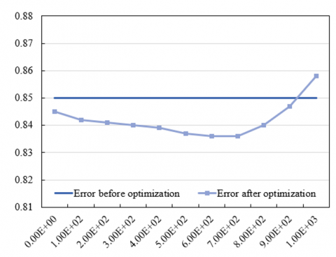
First, by observing changes in the errors before and after optimization under each weight value, it can be seen that, when the weight value is relatively low (such as 0.01 or 0.05) or relatively high (such as 0.9 or 0.95), after optimization, the error values are large still, indicating that under these weight values, the trade-off between patches sampled at different distances from the acupoint may not be reasonable enough. Second, by observing weight values with smaller errors after optimization, it can be found that when the weight is 0.65, the error after optimization is the smallest, which is 7.41E+01, indicating that under this weight, the model has found an optimal trade-off point between patches sampled at different distances from the acupoint. To further verify this conclusion, data near other weight values (such as 0.6 and 0.7) was observed, and it’s found that under these weight values, although the error values after optimization are small still, they are larger than those under a weight of 0.65, and this has further proved the conclusion that 0.65 is the optimal weight. Therefore, this paper took 0.65 as the optimal weight to optimize the performance of the AIP algorithm. Figure 6 compares the errors before and after optimization of the AIP algorithm, which can further verify the correctness of above conclusion.
Next, to analyze the acupoint registration errors of different algorithms, several reference algorithms were introduced for comparison, including two feature point-based methods, SIFT (Scale-invariant feature transform) and ORB (Oriented FAST and Rotated BRIEF), two region-based methods, MI (Mutual Information) and NCC (Normalized Cross-Correlation), a deep learning-based image registration algorithm (FCN), and the proposed model.
According to the data in the Table 2, the acupoint registration errors of various algorithms vary on different samples, and an overall comparison could be made by calculating the average errors on all samples. The average error of SIFT algorithm is about 8.60; the ORB algorithm has an average error of about 4.14; this value for the MI algorithm is about 2.49; as for NCC algorithm and FCN model, the average error is 2.76 and 2.86, respectively; the average error of the proposed method is about 1.27.
Figure 6. Error before and after optimization of the AIP algorithm
Table 2. Acupoint registration errors of different registration algorithms (mm)
|
Sample No. |
SIFT |
ORB |
MI |
NCC |
FCN |
The proposed method |
|
1 |
3.58(2.14) |
1.27(0.83) |
1.39(1.85) |
1.23(1.95) |
1.47(0.62) |
1.05(0.66) |
|
2 |
4.16(3.62) |
2.17(1.06) |
1.25(1.36) |
1.49(1.08) |
1.38(0.67) |
1.02(0.58) |
|
3 |
6.29(4.18) |
3.62(1.27) |
2.48(1.92) |
1.63(1.07) |
1.17(0.91) |
1.07(0.72) |
|
4 |
9.15(4.27) |
4.85(2.16) |
3.27(1.84) |
2.48(1.26) |
2.36(1.69) |
1.06(0.95) |
|
5 |
7.95(5.03) |
3.62(2.59) |
2.06(1.59) |
1.25(2.37) |
2.11(1.95) |
1.17(1.14) |
|
6 |
11.29(6.24) |
3.04(1.35) |
2.64(1.41) |
5.84(7.63) |
2.74(2.88) |
1.03(1.62) |
|
7 |
13.62(7.95) |
4.69(2.57) |
3.05(2.39) |
3.18(3.27) |
3.58(3.04) |
1.48(1.58) |
|
8 |
15.38(9.26) |
9.28(5.36) |
5.28(3.47) |
6.29(5.13) |
8.59(7.24) |
2.39(3.74) |
|
9 |
7.42(3.28) |
3.47(1.02) |
3.62(1.22) |
2.03(1.69) |
2.31(1.69) |
1.05(0.86) |
|
10 |
7.11(6.14) |
5.36(2.57) |
3.59(2.48) |
2.27(2.11) |
2.48(2.57) |
1.84(1.39) |
Figure 7. Accuracy curve
Figure 8. Loss value curve
According to above results, the average error of the proposed method is the smallest, indicating that the proposed method outperforms other methods in terms of acupoint registration accuracy. Comparing with region-based methods (MI and NCC) and deep learning-based method (FCN), the feature point-based image registration algorithms (namely SIFT and ORB) have larger errors since they are not robust enough for local image features. Although the region-based methods (MI and NCC) and the deep learning-based method (FCN) have smaller errors, still, they are greater than the error of the proposed method. To sum up, the proposed method has a higher accuracy in acupoint registration than other reference algorithms, this is because the proposed method has effectively combined multi-scale parallel FCN with adaptive channel attention and other techniques, and the combined effect has improved the acupoint registration accuracy.
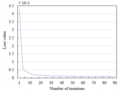
During model training, the iteration was performed 100 times and the loss value curve and accuracy curve were observed. In analysis, 5 key acupoints were selected for detailed discussions. As shown in Figures 7 and 8, the loss value curve decreases gradually during iterations, indicating that the prediction error of the model decreases constantly, and this reflects that the fitting degree of the model to the training data increased constantly during the learning process, which gradually narrowed down the difference between the predicted results and the actual results. This phenomenon indicates that the model can effectively learn acupoint data during training, which is beneficial to accurately positioning the acupoints. In terms of the accuracy curve, the curve rises gradually, indicating that the model’s performance in recognizing acupoint positions is enhancing, after 100 iterations, the model exhibits a good performance in the accuracy of the fifth key acupoint, which has further verified the effectiveness of the model in the acupoint positioning task. Experiments show that the design of the proposed model has fully considered the characteristics of acupoint positioning task, and adopted loss functions, regularization method and optimization strategy that are suitable for the task, and this is conductive to accurately positioning the acupoints. During training, the model can learn features of acupoints from the large amounts of sample data, forming abstract expressions of the acupoints, thereby improving the prediction accuracy.
Table 3 compares the positioning performance of different acupoints, as can be seen from the table, the proposed method’s performance differs in terms of IOU (intersection over union) and distance. At first, in terms of IOU indicators, the IOU Mean indicator and the IOU Worst indicator of the eighth acupoint are 83.62% and 69.38%, respectively, the performance is the best. The IOU Mean indicator and the IOU Worst indicator of the eighth acupoint are 51.27% and 31.42%, respectively, the performance is relatively poor. The values of other acupoints’ IOU indicators are between the two extreme values. By analyzing the Wall dist. (surface distance) indicator and the Centroid dist (centroid distance) indicator of the ninth acupoint, it’s found that the values of the two indicators are 1.62 mm and 2.57 mm respectively, its positioning accuracy is the highest. As for the No. 4 acupoint, the values of the two indicators are 3.95 mm and 5.62 mm, respectively, the positioning accuracy is relatively low, and the values of the two indicators of other acupoints are all between the two extreme values.
Thus, comprehensively analysis of the IOU and distance indicators suggest that, the proposed method show different performance in positioning different acupoints, but its overall performance is good.
Table 3. Positioning of different acupoints
|
Acupoint No. |
IOU[%]Mean |
IOU[%]Worst |
Wall dist.[mm] |
Centroid dist.[mm] |
|
1 |
62.15 |
41.62 |
2.16(3.48) |
3.47(2.14) |
|
2 |
68.35 |
49.28 |
2.04(2.69) |
4.69(2.57) |
|
3 |
51.27 |
31.42 |
2.84(2.04) |
3.57(1.28) |
|
4 |
50.63 |
39.16 |
3.95(4.57) |
5.62(3.15) |
|
5 |
59.68 |
38.02 |
2.85(1.31) |
3.59(1.27) |
|
6 |
54.27 |
25.74 |
2.51(2.69) |
4.16(2.31) |
|
7 |
65.28 |
45.16 |
2.34(2.74) |
4.58(2.67) |
|
8 |
83.62 |
69.38 |
2.69(2.49) |
3.42(1.95) |
|
9 |
67.49 |
47.51 |
1.62(1.04) |
2.57(1.63) |
Table 4. Positioning Detection Rate (PDA) of acupoints
|
Sample group No. |
PDA of acupoints |
|||||||
|
1 |
92.15% |
85.62% |
83.29% |
84.57% |
86.59% |
94.51% |
97.02% |
90.62% |
|
2 |
91.35% |
91.24% |
91.62% |
91.35% |
94.57% |
91.48% |
93.61% |
96.38% |
|
3 |
90.41% |
95.62% |
94.57% |
97.58% |
93.62% |
90.26% |
94.58% |
94.72% |
|
4 |
93.62% |
95.82% |
91.85% |
96.31% |
91.24% |
93.58% |
90.16% |
93.62% |
|
5 |
94.57% |
94.51% |
93.69% |
97.48% |
90.15% |
97.41% |
94.58% |
94.18% |
|
6 |
90.52% |
93.62% |
90.48% |
95.62% |
94.57% |
97.58% |
93.62% |
94.51% |
Table 5. Acupoint pixel difference
|
Sample group No. |
Acupoint pixel difference |
|||||||
|
1 |
1.52 |
2.61 |
2.06 |
2.18 |
2.05 |
1.55 |
1.95 |
1.37 |
|
2 |
1.39 |
1.35 |
1.59 |
1.52 |
1.24 |
1.04 |
1.38 |
1.58 |
|
3 |
1.52 |
1.02 |
1.35 |
1.2 |
1.51 |
1.2 |
1.22 |
1.06 |
|
4 |
1.47 |
1.41 |
1.24 |
1.41 |
1.33 |
1.1 |
1.14 |
1.62 |
|
5 |
1.02 |
1.18 |
1.48 |
1.62 |
1.84 |
1.62 |
1.85 |
1.59 |
|
6 |
1.63 |
1.36 |
1.41 |
1.35 |
1.59 |
1.52 |
1.24 |
1.14 |
Tables 4 and 5 respectively give the detection rate and pixel accuracy error of six groups of acupoints in case of 500 epoch iterations. According to Table 4, the proposed method exhibits different accuracy of acupoint registration on different sample groups. At first, observation of the PDA indicator of different sample groups shows that the accuracy of the 5-th sample group is the best, the highest PDA reaches 97.41%, and the lowest PDA reaches 90.15%, the overall performance is good. In contrast, in terms of accuracy, the performance of the proposed method on Sample Group 1 is poor, although the highest PDA reaches 97.02%, the lowest PDA is only 83.29%. Values of the PDA indicator of other sample groups are all between these two extremes. Analysis shows that the proposed method performs differently in terms of acupoint registration accuracy on different sample groups, but the overall performance is good, which has further verified that the proposed method has certain advantages in terms of acupoint registration.
According to Table 5, it’s known that the proposed method has some differences in acupoint registration accuracy on different sample groups. At first, by observing the acupoint pixel difference of each sample group, it can be seen that the acupoint registration accuracy of the second sample group is the best, the highest pixel difference is 1.59, and the lowest pixel difference is 1.04, the overall performance is good. In contrast, the acupoint registration accuracy of the fifth sample group is the worst, although its lowest pixel difference is 1.85, its highest pixel difference reaches 1.02. Values of this acupoint pixel difference indicator of other sample groups are all between these two extremes. Comprehensive analysis of the acupoint pixel difference indicator of each sample group suggests that, the proposed method shows different acupoint registration accuracy on different sample groups, but its overall performance is satisfactory.
This paper studied a novel AIP algorithm based on image registration. The second chapter proposed the AIP algorithm based on CNN which combines the prior information of acupoint positions in visual images with 3D CNN and can give high accurate positioning results under unfavorable conditions such as image noise, illumination change, or occlusion. The third chapter constructed a multi-scale parallel FCN that introduces multiple techniques, including multi-scale parallel downsampling, spatial pyramid of dilated convolutions, adaptive channel attention mechanism, direction perception, and upsampling, aiming at improving the model’s performance in non-rigid registration of the visual images of massage acupoints. Then, the ideal weight was determined based on the error value before and after the optimization of the positioning algorithm, and analysis of the acupoint registration error of different algorithms showed that the average error of the proposed algorithm is the smallest, indicating that the proposed algorithm outperformed others in terms of acupoint registration performance. After that, by observing the loss value curve and accuracy curve of the proposed model during training, we can see that the proposed model can effectively learn the acupoint data during training, which is conductive to realizing accurate acupoint positioning. At last, this paper gave the positioning detection rate and pixel accuracy difference of six groups of samples when the iteration reaches 500 epochs, and the results indicated that the proposed method showed different positioning performance on different acupoints but its overall performance was good.
This work was supported by the project of Jilin Provincial Science and Technology Department (Grant No.: 20230204096YY and 20230101233JC) and Project of Jilin Provincial Development and Reform Commission (Grant No.: 2023C042-4).
[1] Shu, J., Ding, R., Jin, A., Zhu, H., Chen, S. (2022). Acupoint selection for autonomous massage based on infrared thermography. Traitement du Signal, 39(1): 355-362. https://doi.org/10.18280/ts.390137
[2] Zhu, W., Wang, S. (2021). Design and realization of acupoint tapping massage system with three degrees of freedom based on STM32. In 2021 IEEE 4th Advanced Information Management, Communicates, Electronic and Automation Control Conference (IMCEC), Chongqing, China, pp. 519-522. https://doi.org/10.1109/IMCEC51613.2021.9482084
[3] Jia, Y., Ding, R., Ren, W., Shu, J., Jin, A. (2021). Gesture recognition of somatosensory interactive acupoint massage based on image feature deep learning model. Traitement du Signal, 38(3): 565-572. https://doi.org/10.18280/ts.380304
[4] Sun, F., Liu, Z., Zhang, W. (2021). Clinical acupoint selection for the treatment of functional constipation by massage and acupuncture based on smart medical big data analysis. Journal of Healthcare Engineering, 2021: 9930412. https://doi.org/10.1155/2021/9930412
[5] Hu, W., Sheng, Q., Sheng, X. (2021). A novel realtime vision-based acupoint estimation for TCM massage robot. In 2021 27th International Conference on Mechatronics and Machine Vision in Practice (M2VIP), Shanghai, China, pp. 771-776. https://doi.org/10.1109/M2VIP49856.2021.9665080
[6] Zhu, L., Gong, Y. (2021). Analysis on the application effect of abdominal acupoint massage on feeding intolerance in premature infants. Journal of Healthcare Engineering, 2021: 2883597. https://doi.org/10.1155/2021/2883597
[7] Gong, Y., Zhu, L. (2021). Application effect of acupoint massage on ZUSANLI on premature infants with feeding intolerance and their clinical symptoms. Journal of Healthcare Engineering, 2021: 7772543. https://doi.org/10.1155/2021/7772543
[8] Wang, X.J., He, N.N., Ji, W.B., Yu, L., Zhang, P. (2021). Effect of penetration electroacupuncture combined with intermediate frequency electrotherapy, facial acupoint massage, and cervical reduction on facial nerve function and curative effect of senile refractory facial paralysis. Journal of Healthcare Engineering, 2021: 3776006. https://doi.org/10.1155/2021/3776006
[9] Chen, C., Lu, P., Wang, S., Li, Z. (2020). Posenet based acupoint recognition of blind massage robot. In 2020 5th International Conference on Computer and Communication Systems (ICCCS), Shanghai, China, pp. 251-255. https://doi.org/10.1109/ICCCS49078.2020.9118466
[10] Hu, X., Bo, W., Chai, J. (2019). Research on the visual simulation platform of acupoint massage based on unity 3D. In 2019 IEEE 4th International Conference on Image, Vision and Computing (ICIVC), Xiamen, China, pp. 1-5. https://doi.org/10.1109/ICIVC47709.2019.8981062
[11] Lee, Y.T., Chiang, T.S., Chiu, C.S. (2016). Neural network data modeling and its application on effect analysis of head and shoulder acupoint massage. In 2016 IEEE/ACIS 15th International Conference on Computer and Information Science (ICIS), Okayama, Japan, pp. 1-6. https://doi.org/10.1109/ICIS.2016.7550774
[12] Fu, Z., Wei, Q., Liu, J., Zhang, W. (2022). Application research of automatic acupoint finding based on binocular vision positioning and skeleton recognition. In 2022 8th Annual International Conference on Network and Information Systems for Computers (ICNISC), Hangzhou, China, pp. 590-595. https://doi.org/10.1109/ICNISC57059.2022.00121
[13] Masood, D., Qi, J. (2022). 3D localization of hand acupoints using hand geometry and landmark points based on RGB-D CNN Fusion. Annals of Biomedical Engineering, 50(9): 1103-1115. https://doi.org/10.1007/s10439-022-02986-1
[14] Chen, Y.Z., Maigre, C., Hu, M.C., Lan, K.C. (2017). Localization of acupoints using augmented reality. In Proceedings of the 8th ACM on Multimedia Systems Conference, Taipei, Taiwan, pp. 239-241. https://doi.org/10.1145/3083187.3083225
[15] Zheng, L., Qin, B., Zhuang, T., Tiede, U., Höhne, K.H. (2005). Localization of acupoints on a head based on a 3D virtual body. Image and Vision Computing, 23(1): 1-9. https://doi.org/10.1016/j.imavis.2004.03.005
[16] Yan, Y., Ouyang, J., Ma, X., Zhai, Y. (2014). Feature extraction of anatomical landmark using 2-D Gabor filters for localizing acupoints. Infrared and Laser Engineering, 43(5): 1685-1689.
[17] Yan, Y.G., Ouyang, J.F., Ma, X., Han, Q. (2013). Laser projection system to localize acupoints on face using 3D head model. Biomedical Engineering: Applications, Basis and Communications, 25(4): 1350043. https://doi.org/10.4015/S1016237213500439
[18] Weng, T.C., Lyau, N.M. (2018). Concept development of personified digital prosthesis teaching model–fused application of acupoint-located method by anatomical landmark and 3D composition method. In Innovative Technologies and Learning: First International Conference, ICITL 2018, Portoroz, Slovenia, pp. 631-639. https://doi.org/10.1007/978-3-319-99737-7_68
[19] Chen, Y., Yang, H., Chen, D., Chen, X. (2021). Facial acupoints location using transfer learning on deep residual network. In 2021 7th International Conference on Computer and Communications (ICCC), Chengdu, China, pp. 1842-1847. https://doi.org/10.1109/ICCC54389.2021.9674348
[20] Wang, Y., Ouyang, J.F. (2011). Location and measurement of acupoints on head-model based on structured-light scanning. Applied Mechanics and Materials, 48: 660-663. https://doi.org/10.4028/www.scientific.net/AMM.48-49.660
[21] Lian, Y., Wang, Z., Yuan, H., Gao, L., Yu, Z., Chen, W., Xing, Y., Xu, S., Feng, L. (2020). Partial occlusion face recognition method based on acupoints locating through infrared thermal imaging. In 2020 International Wireless Communications and Mobile Computing (IWCMC), Limassol, Cyprus, pp. 1394-1399. https://doi.org/10.1109/IWCMC48107.2020.9148064
[22] Lin, S., Yi, P. (2019). Human acupoint positioning system based on binocular vision. IOP Conference Series: Materials Science and Engineering, 569(4): 042029. https://doi.org/10.1088/1757-899X/569/4/042029
[23] Wei, Y., Gu, K., Cui, X., Hao, C., Wang, H., Chang, Y. (2016). Strategies for feet massage robot to position the pelma acupoints with model predictive and real-time optimization. International Journal of Control, Automation and Systems, 14: 628-636. https://doi.org/10.1007/s12555-014-0273-3
[24] Hao, C.Z., Han, F. (2012). Review of acupoints positioning and tracking technology for Chinese massage robot. In Advanced Materials Research, 542: 741-744. https://doi.org/10.4028/www.scientific.net/AMR.542-543.741