Faris Keti![]()
© 2024 The author. This article is published by IIETA and is licensed under the CC BY 4.0 license (http://creativecommons.org/licenses/by/4.0/).
OPEN ACCESS
In recent years, the technology of fiber optics communication has experienced immense evolution due to the huge data rates and transmission capacity requirements of emerging communication systems. However, nonlinear effects and dispersion which are challenging impairments are among the main issues that have an impact on the optical fiber systems performance. As a result, to solve this challenging issue, the utilization of a dispersion compensating technique such as Dispersion Compensating Fiber (DCF) or Fiber Bragg Grating (FBG) is an urgent necessity. In this paper, a new model for dispersion compensation utilizing Fiber Bragg Grating is proposed. Tanh apodization and linear chirp functions are added to the proposed model to provide a Linear Chirped FBG. In addition, it has been used with a Gaussian filter of low pass type to enhance the proposed system in terms of performance parameters such as: BER, Q-factor, and eye-diagram. These parameters are the most significant performance measurements that impact any optical communication system. The proposed model is simulated via Optisystem and analyzed via Python. Simulation results for different lengths of fiber show that the BER, Q-factor, and eye diagrams of the proposed model have a better performance compared to that of the other systems where either no FBG is applied or a traditional uniform FBG is used. The Q-factor values and BER values for 40km fiber length were 29.5524 and 9.3407*10-182 for the system model proposed in this study, 13.9969 and 6.5823*10-45 for the system with uniform FBG, and 5.0736 and 1.1792*10-7 for the system without FBG. Finally, the eye diagrams of the proposed model also show a better opening compared to other systems.
dispersion compensation, fiber optics, Fiber Bragg Grating, Gaussian filter, Optisystem
The traditional generations of communication systems (First Generation-to-Fourth Generation) couldn't support the increased demands on mobile networks. As a result, an emergent wireless network architecture is needed. Therefore, Fifth Generation (5G) is a promised solution and a great opportunity to offer this integrated framework [1]. 5G is predicted to become a backbone for future communication systems requirements. 5G systems can provide a sustainable infrastructure which can overcome the challenging demands of traditional generations and handle the further development of emerging communication systems [2]. In 5G, there is a massive amount of traffic for each user and the network service providers are required to adapt with these demands [3]. Therefore, various techniques such as C-RAN [4], RoF [5], MIMO [6], etc. are suggested [7]. In response, optical fiber system become one of the robust systems to be deemed. These proposed techniques need to use fiber optics because of its ability to fulfill 5G requirements due to its low attenuation and large transmission bandwidth [8]. However, nonlinear effects and dispersion which are challenging impairments are among the main issues that have an impact on the optical fiber systems performance [9]. Dispersion is known as the broadening of the light pulse while spreading in a fiber optical cable. It leads to weak SNR, affects the quality of the system, and results in lower throughputs. As light pulses with multiple wavelengths propagate through a fiber optical cable, they suffer from the dispersion. As a result, errors occur at the receiver side and prevents the received signal to be detected correctly [10].
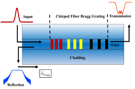
The favored solution for dispersion compensation is Fiber Bragg Grating (FBG) due to its ability to compensate dispersion at different wavelength variations. Bragg gratings have an index of refraction with a periodic variation within the medium of propagation [11]. If the refractive index’s period changes along the grating length, then it’s referred to as chirp FBG (CFBG) [12]. Uniform FBG (UFBG) is characterized by a narrow reflection spectrum and is frequently utilized in optical filtering. CFBG is characterized by a wide reflectance spectrum and its able to reflect light signals of different frequencies, which are mainly used for the purposes of dispersion compensation [13]. Figure 1 shows the scheme of CFBG.
As the signal spreads along the CFBG, distinct wavelength components will be reflected at varying instances through the grating. The transmitted optical signal comprises multiple wavelength components, and these elements will be reflected at different locations along the grating based on their respective wavelengths. Therefore, this ability can be used for dispersion compensation. Compared to other dispersion compensation methods such as Dispersion Compensating Fiber, CFBG offers several advantages. These advantages include a smaller physical size, low insertion loss, negligible nonlinearities, and more cost-effective [14, 15].
Figure 1. CFBG scheme [16]
Many researchers have considered and discussed this topic. Mainly, their researches have been carried out to discover the utilization of Linear-CFBG in optical fiber systems and specifically for purposes of dispersion compensating. In Sayed et al. [17], four cascaded FBGs are connected to minimize the optical signal’s spectral width of optical signal at transmitter side and a CFBG is used at the receiver for dispersion compensation. However, in their proposed system, they didn’t focus on dispersion compensation as they concerned more on the reduction of the width of spectrum via the utilization of various apodization functions. In Meena and Meena [18], the authors reported the impact that CFBG has in compensating dispersion in communication systems. However, they were interested more in the utilization of their proposed model in DWDM systems and obtained their simulations results via an old version of Optisystem. On the other hand, some of the researches were carried out about the role of CFBG in improving the sensitivity of the sensors such as the previous research [16]. In this research the use of apodization Tanh and linear functions with CFBG along with some other materials such as polymer materials to enhance sensors’ sensitivity were reported. Furthermore, the application of CFBG in the applications of sensors and its usage in some of the biomedical field’s applications were conducted in the previous researches [19-21].
Since the fronthaul link of 5G’s C-RAN architecture is almost a fiber optic link. The maximum proposed length of that link between the Remote Radio Heads (RRHs) and the Base Band Units (BBUs) of this architecture is 40km [22]. Furthermore, to the best of our knowledge, the application of Linear-CFBG along with Tanh apodization and linear chirp functions in such fronthaul links and system architecture were not covered very well in the related works. Therefore, to compensate dispersion in such system architectures, a new model proposed in this study. The proposed model is based on the utilization of FBG along with linear chirp and Tanh apodization functions to provide a new Linear-CFBG model. Furthermore, to enhance the performance of the model in terms of performance parameters a Gaussian filter of low pass type is integrated into the model. Finally, to ensure its application in 5G C-RAN’s fronthaul link, the superior performance of the proposed model compared to that of the related works at the fiber length of 40km is also conducted. The addition of the Gaussian filter to the receiver side of the proposed model has a significant role in its performance enhancement. The remaining of this paper is organized as follow. The main theory of the topic and analytical mathematics are presented in section 2. Section 3 presents the applied method. The obtained results and discussions are provided in Section 4. While Section 5 concludes the paper.
Due to the CFBG’s characteristics, when the signal spreads in it, the signal is filtered, part of it is reflected and some of the signal is forwarded. The reflected part is referred to as Bragg wavelength. It can be represented as shown in Eq. (1) [23]:
$\lambda_{\mathrm{bg}}=2 \mathrm{n}_{\mathrm{eff}} \Lambda$ (1)
where,
$\lambda_{b g}$: the wavelength of Bragg,
$n_{e f f}$: effective refractive index, and
$\Lambda$: the period of grating.
Then, $n_{e f f}$ along any fiber can be calculated as shown in Eq. (2):
$\mathrm{n}_{\mathrm{eff}}(\mathrm{p})=\mathrm{n}_0+\mathrm{f}(\mathrm{p}) \Delta \mathrm{n}_{\mathrm{am}} \mathrm{v} \cos \left(\left(\frac{2 \pi}{\Lambda}\right)+\theta(\mathrm{p})\right)$ (2)
where,
p: position,
$n_0$: initial index of refraction,
f(p): the function of apodization,
$\Delta n_{a m}$: the amplitude of the refractive index of modulation,
v: the visibility of fringe, and
$\theta(p)$: the function of chirp.
Bragg wavelength is primarily influenced by two factors: the grating period and the effective refractive index distribution as explained in Eq. (1). On the other hand, as it has been proofed mathematically in Eq. (2), the FBG’s effective refractive index is affected by the chirp type and apodization profile. There are different types of chirping on FBGs as shown in Table 1.
In Linear-CFBG, the CFBG’s grating is linearly arranged along with the FBG’s core. Therefore, the distances between its gratings are linear. Based on Table 1, the period of grating of Linear-CFBG is presented in Eq. (3):
$\Lambda(p)=\Lambda_0-\frac{p-0.51}{l} \Delta$ (3)
where,
$\Lambda(p)$: grating period,
$\Lambda_0$: the initial period of grating,
l: length of grating, and
$\Delta$: total chirp.
Table 1. CFBG grating’s types
|
Type of Grating (CFBG) |
Period of Grating |
Description |
|
Linear |
$\Lambda(p)=\Lambda_0-\frac{p-0.5 l}{l} \Delta$ |
The gratings’ distance is linear. |
|
Quadratic |
$\Lambda(p)=\Lambda_0-\left[\left(\frac{p}{l}\right)^2-0.25\right] \Delta$ |
The gratings’ distance is based on the quadratic function. |
|
Square-Root |
$\Lambda(p)=\Lambda_0-\left[\sqrt{\frac{p}{l}}-\frac{1}{\sqrt{2}}\right] \Delta$ |
The gratings’ distance is equal to the function of square root. |
|
Cubic-Root |
$\Lambda(p)=\Lambda_0-\left|\sqrt[3]{\frac{p}{l}}-\frac{1}{\sqrt[3]{2}}\right| \Delta$ |
The gratings’ distance is equal to the function of cubic root. |
In this paper, the Linear-CFBG and Tanh apodization function are used. In addition, to improve the Q-factor and the eye-diagram, and thus enhance the system performance a Gaussian filter of low pass type is integrated into the proposed model.
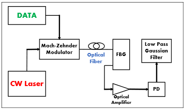
OptiSystem which is a simulation software is used in this study to design and simulate the proposed new model of dispersion compensation. It is a simulation software of optical fiber communication systems released by Optiwave. OptiSystem is vastly used to help in testing, planning, simulating, and designing optical fiber systems [24]. Figure 2 shows the scheme of the system proposed in this study.
Figure 2. The proposed model’s schematic setup
In the system model proposed in this study, FBG is used with a linear chirping function and a Tanh apodization function. While, because of the significant effect of the length of grating on FBG functionality, an optimal length of grating is employed. Furthermore, a Gaussian filter is integrated into the electrical system part following the photodetector on the receiver side. The filter is of low pass type and its integration is intended to boost system performance by enhancing both the Q-factor and the openness of the eye diagram. The proposed model is intended to work at 193.1THz frequency and 1550nm wavelength. A CW-Laser at the designated frequency and an optimal output power is applied. The CW-Laser's output signal and the bit rate’s signal encoded by a pulse generator are then combined at MZM modulator. Then, the modulated signal is transferred to the receiver side via a SMF. To examine the influence of fiber length on system performance in terms of Q-factor, BER, and the eye diagram, different lengths of fiber are used. Moreover, the impact of various output powers of CW-laser on system performance is taken into consideration. Finally, the influence of the effective index of CFBG along with various grating length’s values on the performance of the system in terms of Q-factor are examined.
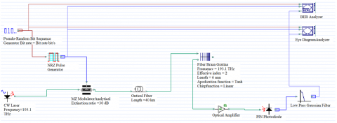
The simulation setup for the proposed Linear-CFBG compensation model is shown in Figure 3. The addition of the Tanh apodization and linear chirp functions, and the Gaussian filter of low pass type being added in the receiver side of the proposed model can be noticed very clearly. As it can be noticed from the figure, the 10Gbps data rate are encoded with the pulses of the NRZ pulse generator via the utilization of the pseudo-random bit sequence generator. The CW-Laser source’s signal and the pulse generator’s signal are combined at MZM with extinction ratio of 30dB. Then, the signal is transmitted to the receiver side over SMF of different lengths. The dispersion, attenuation, and dispersion slope of the optical fiber are set to be 17ps/nm/km, 0.02dB/km, and 0.005ps/nm2/km respectively.
Figure 3. The proposed model’s simulation setup
Table 2. Parameters’ values of the model of Figure 3
|
Parameter |
Value |
|
Data Rate |
10Gbps |
|
Source Frequency |
193.1THz |
|
Extinction Ratio of Mach-Zehnder Modulator |
30 dB |
|
The length of Single Mode Fiber (SMF) |
4km-40km |
|
Attenuation |
0.02dB/km |
|
Dispersion |
17ps/nm/km |
|
Dispersion Slope |
0.005ps/nm2/km |
|
Apodization Function |
Tanh |
|
Chirp Function |
Linear |
|
The Gain of Optical Amplifier |
10dB |
|
The Noise Figure of Optical Amplifier |
4dB |
|
PIN Photodiode Responsivity |
1 A/W |
|
Cut-off Frequency of Low Pass Gaussian Filter |
0.75 * The Symbol Rate |
On the other hand, the functions of CFBG are set to Tanh and linear respectively. Then, to amplify and improve the signal, an optical amplifier is added. The amplifier noise figure and gain are set to 4dB and 10dB respectively. After that, the PIN photodiode is used to receive the signal and its responsivity is set to 1 A/W. Finally, a Gaussian filter of a low pass type is connected. The cut-off frequency of the filter is set to be 0.75 of symbol rate. The eye-diagram and BER analyzers are used to show the eye diagram, Q-factor, and BER results of the received signal. To further simplify the explanation of the simulation setup for the proposed model which is shown in Figure 3, the parameters of the proposed model and their corresponding values are summarized in Table 2.
Because, both effective index and grating length are important factors that have a significant impact on the performance of FBG and the entire system, their values have been calculated by the simulations for a fiber length of 40km as shown in Table 3. Based on the obtained results of Table 3, the best Q-factor value for effective index of 1 is (10.9937) at FBG grating length of 7mm, effective index of 2 is (29.5524) at FBG grating length of 6mm, effective index of 3 is (25.2222) at FBG grating length of 7mm, and effective index of 4 is (24.3607) at FBG grating length of 7mm. It has been concluded that the best Q-factor value from all the combinations of effective index and FBG grating length for the entire system is obtained at effective index of 2 and FBG grating length of 6mm which is (29.5524). Therefore, these determined values of effective index and grating length (2, 6mm) have been considered for the rest of the simulations of this study.
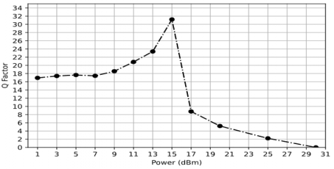
Furthermore, after conducting additional simulations using the aforementioned simulation tools [25] to identify the optimal CW-laser output power for a 40km fiber length, it was found that a power setting of 15dB provides the best Q-factor result for this study’s system as shown in Figure 4. After identifying the optimal values for influencing factors (input power, effective index, and grating length) in addition to the previously determined parameters of the system. Finally, the Min-BER and the Max Q-factor are calculated for the proposed system across various length instances of fiber, the system model without FBG, and the system model with uniform FBG as shown in Table 4.
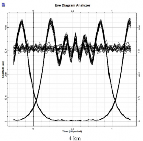
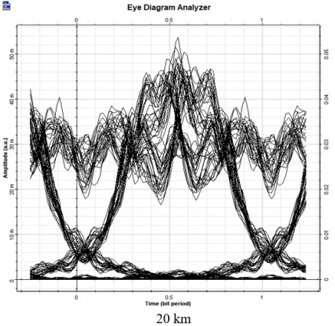
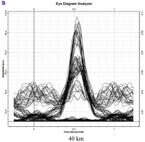
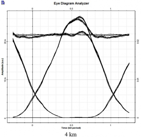
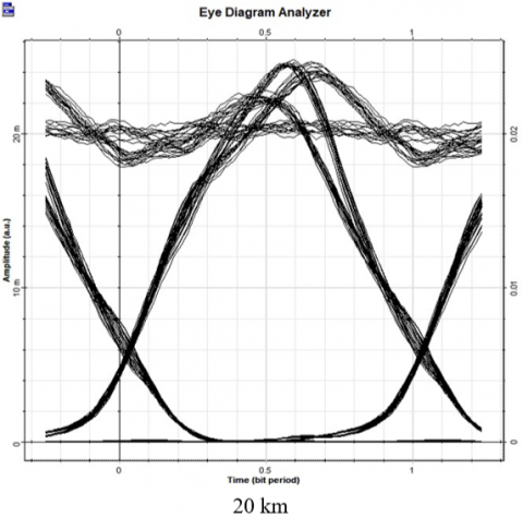
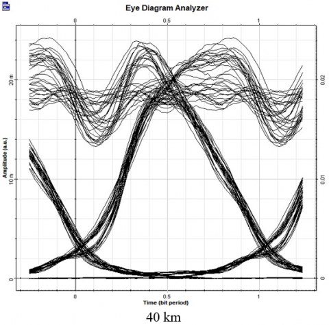
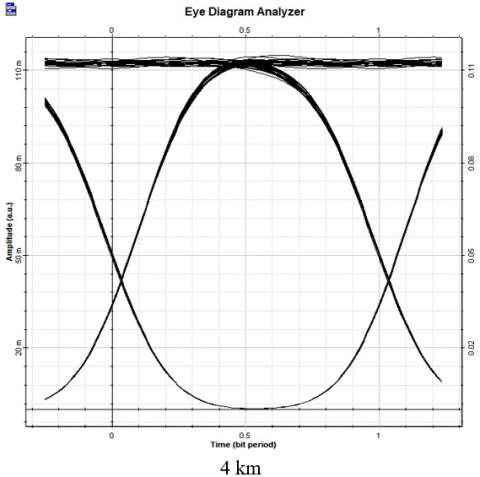
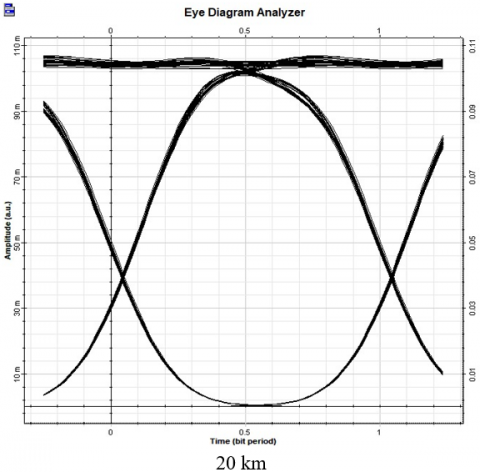
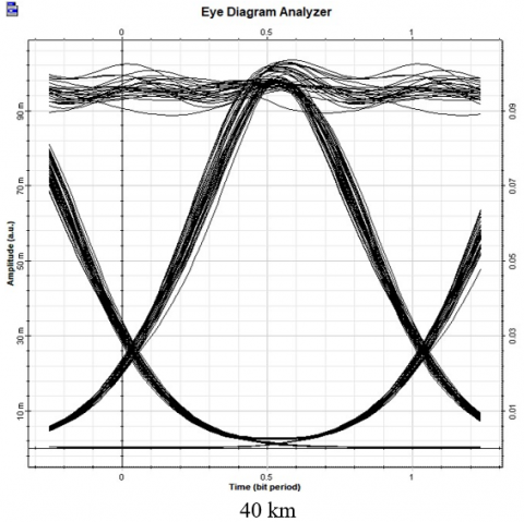
Furthermore, the eye diagrams for various fiber lengths are acquired as displayed in Figures 5, 6, and 7 in sequence. The results of simulation in both the figures and the table explain the superior performance of the new proposed model of this study. They confirmed its superiority compared to the other two systems through the performance measurement metrics.
Figure 4. The values of Q-factor versus input power
Table 3. The values of Q-factor corresponding to both FBG length and effective index
|
FBG Length (mm) |
Effective Index |
|||
|
1 |
2 |
3 |
4 |
|
|
1 |
10.0535 |
10.8633 |
9.6935 |
10.4016 |
|
2 |
9.5467 |
9.2611 |
11.7121 |
13.7517 |
|
3 |
8.9570 |
10.4999 |
17.0612 |
16.4148 |
|
4 |
9.99 |
13.5951 |
22.3156 |
17.88 |
|
5 |
10.3995 |
18.8694 |
21.87 |
19.9871 |
|
6 |
10.5601 |
29.5524 |
18.5411 |
20.6538 |
|
7 |
10.9937 |
21.8183 |
25.2222 |
24.3607 |
Table 4. The values of Max Q-factor and Min BER at various lengths of for different models
|
Fiber Leng-th (Km) |
Without FBG Model |
With FBG Model |
Proposed Model |
|||
|
MaxQ-factor |
Min-BER |
Max Q-factor |
Min-BER |
Max Q-factor |
Min-BER |
|
|
4 |
40.8194 |
0 |
85.6243 |
0 |
136.548 |
0 |
|
8 |
15.7909 |
1.0860*10-56 |
64.6501 |
0 |
118.034 |
0 |
|
12 |
14.9098 |
1.0555*10-50 |
68.0275 |
0 |
104.7 |
0 |
|
16 |
10.7701 |
2.0132*10-27 |
39.157 |
0 |
87.8136 |
0 |
|
20 |
7.8601 |
1.7650*10-15 |
22.1339 |
4.1351*10-109 |
76.2916 |
0 |
|
24 |
5.4287 |
1.5705*10-8 |
19.7062 |
6.7105*10-87 |
57.4176 |
0 |
|
28 |
8.7930 |
2.6667*10-18 |
18.8204 |
1.8707*10-79 |
43.0726 |
0 |
|
32 |
8.4321 |
1.2624*10-17 |
18.54 |
3.8776*10-77 |
33.7275 |
7.8817*10-250 |
|
36 |
5.3761 |
2.8953*10-8 |
15.5261 |
9.1700*10-55 |
31.4359 |
2.9906*10-217 |
|
40 |
5.0736 |
1.1792*10-7 |
13.9969 |
6.5823*10-45 |
29.5524 |
9.3407*10-182 |
Figure 5. Eyes diagrams for various lengths of fiber before FBG
Figure 6. Eye diagrams for various lengths of fiber with Uniform FBG
Figure 7. Eye diagrams for various lengths of fiber with the proposed Linear-CFBG
The traditional generations of communication systems (1G-4G) can't support the huge data rates and transmission capacity requirements of emerging communication systems. In beyond 4G systems, higher capacity, massive data rates, low latency, and improved security must be provided. As a result, a new wireless network architecture is required. Therefore, 5G is a promised candidate that is predicted to become a backbone for future communication systems requirements. 5G systems can provide a sustainable infrastructure which can overcome the challenging demands of traditional generations and handle the further development of emerging communication systems. In response to the diverse innovative technologies been used in 5G mobile communications, one of the robust systems to be considered is fiber optics. These proposed techniques need to use fiber optics because of its ability to fulfill 5G requirements due to its advantageous characteristics such as low attenuation and large transmission bandwidth. However, nonlinear effects and dispersion which are challenging impairments are among the main issues that have an impact on the optical fiber systems performance.
As a result, to solve this challenging issue, the utilization of dispersion compensating techniques such as DCF and FBG were used in traditional studies. However, to the best of our knowledge, the application of Linear-CFBG along with Tanh apodization and linear chirp functions in 5G’s C-RAN architecture were not covered very well in the related works. Therefore, since the fronthaul link of 5G’s C-RAN architecture is almost a fiber optic link. Whereas the maximum proposed length of that link between the RRHs and the BBUs of this architecture is 40km. As a result, a new model for dispersion compensation utilizing FBG is proposed in this paper. linear chirp and Tanh apodization functions are added to the proposed model to provide a Linear CFBG. In addition, it has been used with a Gaussian filter of low pass type to enhance the performance of the proposed model in terms of performance parameters. These performance parameters are the most significant metrics that impact any optical communication system.
On the other hand, to ensure its application in 5G C-RAN’s fronthaul link, the performance comparison of the proposed model in this study to that of the related works is also conducted. It could be noticed that the addition of the Gaussian filter to the receiver side of the system had a significant role in its performance enhancement. Based on the simulation results, it could be confirmed that the linear chirp and the Tanh apodization functions, and the Gaussian filter have their impact on the performance of the proposed model of this study. In addition, the optimum values of effective index and grating length of FBG were obtained via the simulations. Then the Max Q-factor, Min BER, and eye diagrams of the proposed and the traditional models with different fiber lengths and input powers were determined. It could be concluded that for a 10Gbps data rate system, operating at 193.1THz and 1550nm wavelength, and different fiber lengths, the optimum values of input power, effective index, and FBG’s grating length are15dBm, 2 and 6mm respectively. It is also concluded that the performance measuring parameters of the proposed system show better results and a superior performance than that of the compared system models.
[1] Agiwal, M., Kwon, H., Park, S., Jin, H. (2021). A survey on 4G-5G dual connectivity: Road to 5G implementation. IEEE Access, 9: 16193-16210. https://doi.org/10.1109/ACCESS.2021.3052462
[2] Khurpade, J.M., Rao, D., Sanghavi, P.D. (2018). A survey on IOT and 5G network. In 2018 International conference on smart city and emerging technology (ICSCET), Mumbai, India, pp. 1-3. https://doi.org/10.1109/ICSCET.2018.8537340
[3] Navarro-Ortiz, J., Romero-Diaz, P., Sendra, S., Ameigeiras, P., Ramos-Munoz, J.J., Lopez-Soler, J.M. (2020). A survey on 5G usage scenarios and traffic models. IEEE Communications Surveys & Tutorials, 22(2): 905-929. https://doi.org/10.1109/COMST.2020.2971781
[4] Kadan, F.E., Yılmaz, A.Ö. (2021). A theoretical performance bound for joint beamformer design of wireless fronthaul and access links in downlink C-RAN. IEEE Transactions on Wireless Communications, 21(4): 2177-2192. https://doi.org/10.1109/TWC.2021.3109837
[5] Xie, C., Bai, W., Li, P., Du, Y., Zhong, N., Pan, W., Zou, X. (2022). Bidirectional WDM multi-nodes analog radio-over-fiber mobile fronthaul link enhanced by photonic integrated devices. IEEE Photonics Journal, 14(6): 1-7. https://doi.org/10.1109/JPHOT.2022.3220821
[6] Feng, R., Wang, C.X., Huang, J., Gao, X., Salous, S., Haas, H. (2022). Classification and comparison of massive MIMO propagation channel models. IEEE Internet of Things Journal, 9(23): 23452-23471. https://doi.org/10.1109/JIOT.2022.3198690
[7] Al-Falahy, N., Alani, O.Y. (2019). Millimetre wave frequency band as a candidate spectrum for 5G network architecture: A survey. Physical Communication, 32: 120-144. https://doi.org/10.1016/j.phycom.2018.11.003
[8] de Souza Lopes, C.H., Lima, E.S., Pereira, L.A.M., et al. (2020). Non-standalone 5G NR fiber-wireless system using FSO and fiber-optics fronthauls. Journal of Lightwave Technology, 39(2): 406-417. https://doi.org/10.1109/JLT.2020.3029500
[9] Keti, F., Atroshey, S.M., Hamadamin, J.A. (2022). A review of the impairments and challenges of radio over fiber technology and their mitigation strategies. In 2022 International Conference on Computer Science and Software Engineering (CSASE), Duhok, Iraq, pp. 95-100. https://doi.org/10.1109/CSASE51777.2022.9759619
[10] Chen, Y., Dai, H., Si, H., Wang, F., Wang, B., Wang, L. (2022). Long-haul high precision frequency dissemination based on dispersion correction. IEEE Transactions on Instrumentation and Measurement, 71: 1-7. https://doi.org/10.1109/TIM.2022.3214617
[11] Sliti, M. (2022). 16 Channels WDM radio over fiber system with DCF and FBG compensators. In 2022 27th Asia Pacific Conference on Communications (APCC), Jeju Island, Korea, pp. 54-59. https://doi.org/10.1109/APCC55198.2022.9943747
[12] Tosi, D. (2018). Review of chirped Fiber Bragg Grating (CFBG) fiber-optic sensors and their applications. Sensors, 18(7): 2147. https://doi.org/10.3390/s18072147
[13] Xia, P., Zhang, L.H., Lin, Y. (2019). Simulation study of dispersion compensation in optical communication systems based on optisystem. Journal of Physics: Conference Series, 1187(4): 042011. https://doi.org/10.1088/1742-6596/1187/4/042011
[14] Düendorfs, V., Spolitis, S., Bobrovs, V. (2017). Comparison of dispersion compensation methods for 40Gbit/s WDM-PON transmission systems. In 2017 Progress in Electromagnetics Research Symposium-Spring (PIERS), St. Petersburg, Russia, pp. 2431-2436. https://doi.org/10.1109/PIERS.2017.8262159
[15] Gharat, A., Nawale, P., Waje, P., Borse, B., Patel, D. (2020). Performance analysis of CFBG and DCF based on dispersion compensation. In 2020 IEEE International Students' Conference on Electrical, Electronics and Computer Science (SCEECS), Bhopal, India, pp. 1-5. https://doi.org/10.1109/SCEECS48394.2020.170
[16] Irawan, D., Ramadhan, K., Saktioto, S., Marwin, A. (2022). Performance comparison of Topas chirped Fiber Bragg Grating sensor with Tanh and Gaussian apodization. Indonesian Journal of Electrical Engineering and Computer Science, 26(3): 1477-1485. https://doi.org/10.11591/ijeecs.v26.i3.pp1477-1485
[17] Sayed, A.F., Mustafa, F.M., Khalaf, A.A., Aly, M.H. (2021). Spectral width reduction using apodized cascaded Fiber Bragg Grating for post-dispersion compensation in WDM optical networks. Photonic Network Communications, 41: 231-241. https://doi.org/10.1007/s11107-021-00926-y
[18] Meena, D., Meena, M.L. (2020). Design and analysis of novel dispersion compensating model with chirp Fiber Bragg Grating for long-haul transmission system. Optical and Wireless Technologies: Proceedings of OWT 2018, Springer Singapore, pp. 29-36. https://doi.org/10.1007/978-981-13-6159-3_4
[19] Rosolem, J.B., Penze, R.S., Floridia, C., et al. (2020). Dynamic effects of temperature on FBG pressure sensors used in combustion engines. IEEE Sensors Journal, 21(3): 3020-3027. https://doi.org/10.1109/JSEN.2020.3025376
[20] Peng, J., Jia, S., Yu, H., Kang, X., Yang, S., Xu, S. (2020). Design and experiment of FBG sensors for temperature monitoring on external electrode of lithium-ion batteries. IEEE Sensors Journal, 21(4): 4628-4634. https://doi.org/10.1109/JSEN.2020.3034257
[21] Presti, D.L., Massaroni, C., Leitão, C.S.J., et al. (2020). Fiber Bragg Gratings for medical applications and future challenges: A review. IEEE Access, 8: 156863-156888. https://doi.org/10.1109/ACCESS.2020.3019138.
[22] Alimi, I.A., Teixeira, A.L., Monteiro, P.P. (2017). Toward an efficient C-RAN optical fronthaul for the future networks: A tutorial on technologies, requirements, challenges, and solutions. IEEE Communications Surveys & Tutorials, 20(1): 708-769. https://doi.org/10.1109/COMST.2017.2773462
[23] Kaur, M., Sarangal, H. (2015). Simulation of optical transmission system to compensate dispersion using chirped Fiber Bragg Grating (FBG). International Journal of Advanced Research in Computer and Communication Engineering. https://doi.org/10.17148/IJARCCE.2015.4281
[24] Atieh, A., Mirza, J., Ghafoor, S. (2022). Optical fiber sources design in optisystem software. In 2022 Photonics North (PN), pp. 1-1. https://doi.org/10.1109/PN56061.2022.9908384
[25] Wang, Z., Bu, D., Sun, A., Gou, S., Wang, Y., Chen, L. (2022). An empirical study on bugs in python interpreters. IEEE Transactions on Reliability, 71(2): 716-734. https://doi.org/10.1109/TR.2022.3159812