Pawan Dubey![]() | Tirupathiraju Kanumuri
| Tirupathiraju Kanumuri![]() | Ritesh Vyas
| Ritesh Vyas![]() | Keerty Venkata Sri Ramachandra Murthy
| Keerty Venkata Sri Ramachandra Murthy![]() | Chandan Kumar Choubey
| Chandan Kumar Choubey![]() | Durgesh Nandan*
| Durgesh Nandan*![]()
© 2023 IIETA. This article is published by IIETA and is licensed under the CC BY 4.0 license (http://creativecommons.org/licenses/by/4.0/).
OPEN ACCESS
The inherent curvature in palm lines can pose challenges for palmprint recognition, particularly at lower resolutions where wrinkles become indistinguishable, leading to performance degradation. To address these issues, this study introduces a novel methodology employing curvi-linear anisotropic Gaussian filter-based Combined Differential Concavity and Infirmity (CDCI) codes. The use of curved filters has been proposed to represent curved palm lines more accurately, while anisotropic filtering is expected to enhance the extraction of blurred palm lines. The new representation, grounded in curvi-linear anisotropic Gaussian filtering, is posited to improve the recognition system's performance by effectively addressing these challenges. The proposed approach's effectiveness has been tested using the touchless IITD database and the contact-based PolyU 2D database. The experimental results suggest that the proposed methodology surpasses the performance of state-of-the-art coding-based procedures in palmprint recognition with the improvement of 3.82% and 36.36% in recognition rate and equal error rate.
palmprint recognition, curvilinear anisotropic filters, differential concavity, differential infirmity bits
Biometric traits such as palm prints have garnered attention due to the ease of capturing templates, high discriminative features, universal acceptability, richness in features even at low resolution, and permanence. The inherent features for differentiating one person's palmprint from another's lie in the edges, comprised of principal lines and wrinkles [1]. Principal lines, due to slower intensity variation, are considered low-frequency information, while wrinkles, with their abrupt intensity changes, represent high-frequency information. Moreover, these inherent lines display curvature [1].
Past approaches primarily employed the even part of Gabor filters for palmprint representation, akin to Laplace of Gaussian (LOG) filters [2]. However, LOG filters are susceptible to noise and demonstrate an imbalance in the susceptibility to low and high-frequency information [3]. This approach failed to represent both principal lines and wrinkles, despite the enhancement of system performance from wrinkles [4]. Given that line frequency within local neighborhoods of the palmprint is fixed within a certain range, accurate feature extraction becomes dependent on the challenging task of frequency estimation for specific local neighborhoods.
Existing palmprint representation algorithms can be broadly classified into structural, subspace, statistical, transform, and coding-based approaches [5]. Among these, coding approaches, a subcategory of transform-based algorithms [6-9], have shown remarkable performance, ease in implementation, and rapid feature extraction.
The evolution and development of coding approaches has seen numerous research contributions. Zhang et al. [4] presented the first binary feature representation for palmprint, in which binary features were extracted through zero crossings of a filtered image using a single-orientation Gabor filter. However, given that palm lines are oriented in various directions, a single orientation proved insufficient for comprehensive palmprint representation. Subsequent research saw the development of fusion codes [10], dominant orientation extraction and encoding [11-13], binary orientation co-occurrence vector (BOCV) [14], the incorporation of fragile bits with BOCV [15], XOR-SUM codes [16], Double Orientation Code (DOC) [17], half orientation codes (HOC) [18], discriminative and robust dominant orientation (DRCC) [19], neighboring Directional Indicator Code (NDIC) [20], and banana filter-based concavity code [21].
Palmprint representation can be enhanced using Anisotropic filtering (AF). Unlike Gabor filters, AF is frequency-independent and eliminates the need for correct frequency assessments within local neighborhood blocks. The filters serve as a low-resolution smoothing function along the line direction, and as orthogonal smoothing filters perpendicular to the palm lines. AF has been shown to be robust to noise and distortion and capable of collecting evidence along inherently interrupted lines [22, 23]. In light of these advantages and the curved characteristics of palm lines, this paper proposes a novel Curvilinear Anisotropic Gaussian filter (CAGF) based combined differential concavity and infirmity, (CDCI) codes for palmprint representation.
The proposed CAGF, derived from AF, retains the frequency-independency towards palm line width and the noise removal capability of AF. Furthermore, the curvilinear filters are embedded with curvature in their shapes, providing a true representation of curved palm lines within palmprints. The performance of the proposed filter-based method is tested with the IIT Delhi touchless database [24] and the PolyU 2D database [25]. Both databases were chosen for their diverse inter and intra-class variations within their palmprint samples in terms of illumination and palm line width, and for their different capture techniques and environmental conditions.
The key contributions of this work include the proposal of the novel Curvilinear Anisotropic Gaussian filter (CAGF) that incorporates the properties of anisotropic filters and considers the curved nature of the palm lines. The CAGF is frequency-independent and capable of representing both types of palm lines, i.e., principal lines and wrinkles, irrespective of their frequencies. The novel CDCI codes are a combined binary representation of the curvature property of palm lines and the precise filtered image coefficient representation. This method discards repeated coefficients that can be captured at different orientations, known as infirmity codes. Thus, the proposed CDCI codes take advantage of the true structural representation of palm lines and incorporate vital features to enhance recognition performance.
The rest of the paper is organized as follows: Section 2 discusses the mathematical preliminaries to derive the CAGF, Section 3 elaborates the steps for generating the CDCI and the template matching, Section 4 discusses experimental results, and Section 5 concludes the paper.
2.1 The curvilinear anisotropic gaussian filter
Let X= [x1, x2] be the coordinates of the of the 2D palmprint image, and also assume that U= [u1, u2]T be the Cartesian coordinates of the 2-D Gaussian convolution kernel in a certain orientation, where u1 and u2 are anticipated to be parallel and orthogonal coordinates to the palm lines, respectively. Further, let the anticlockwise angle between the x1 and u1 is denoted by θ, then the coordinates, U from X, can be computed as:
$U=\left[\begin{array}{cc}1 / \alpha & 0 \\ 0 & 1 / \beta\end{array}\right]\left[\begin{array}{cc}\cos \theta & \sin \theta \\ -\sin \theta & \cos \theta\end{array}\right] X^T$ (1)
where, $T$ is the transpose operator, $\alpha$ and $\beta$ are the contour adjustment parameters of the filter. The AFs are formulated by combining the Gaussian function in one direction, and second derivative of the Gaussian function in other direction (orthogonal direction) [26]. An anisotropic Gaussian filter kernel tuned to orientation $\theta$, is described as a function of $U$.
$\operatorname{AGF}\left(u_1, u_2\right)=\left(4 u_1^2-2\right) \times\exp \left(-\left(\left[\begin{array}{ll}u_1, & u_2\end{array}\right]\left[\begin{array}{ll}u_1, & u_2\end{array}\right]^T\right)\right)$ (2)
The curved 2-D function from, f (m, n), can be derived by introducing the curvature into the function variables, m and n. This curvature property [21] can be deployed by the operator, Cc, which is defined as:
$C_c\left(\begin{array}{l}m \\ n\end{array}\right)=\left[\begin{array}{c}m-\chi \cdot n^2 \\ n\end{array}\right]$ (3)
where, $\chi$denotes curvature parameter and represented mathematically as follows:
$\chi=c \times .01 \times(-1)^\gamma$ (4)
Concavity $= \begin{cases}(+) v e & \text { if } \gamma=0 \\ (-) v e & \text { if } \gamma=1\end{cases}$
and $c$ is the parameter related to curvature. Therefore, the coordinates, to acquire curved 2-D Gaussian filter kernel, denoted as $U^c=\left[u_1^{c \gamma} u_2^{c \gamma}\right]$ at certain orientation, $\theta$, are obtained using following equation:
$\left[u_1^{c \gamma}, u_2^{c \gamma}\right]=C_c\left(\left[\begin{array}{cc}\cos \theta & \sin \theta \\ -\sin \theta & \cos \theta\end{array}\right] X^T\right)$ (5)
where, Cc introduces the curvature property up to the extent of c in $u_1^{c \gamma}$ and $u_2^{c \gamma}$. Thus, the $C_{A G F}$$\begin{aligned} & c \gamma \\ & \theta\end{aligned}$ can be obtained by substituting the coordinates, obtained through Eq. (6), into Eq. (7), and can be represented as:
$\begin{aligned} C_{A G F \theta}\,^{c \gamma}\left(u_1^{c \gamma}, u_2^{c \gamma}\right) & =\left(4\left(u_1^{c \gamma}\right)^2-2\right) \times\exp \left(-\left(\left[\begin{array}{ll}u_1^{c \gamma}, & u_2^{c \gamma}\end{array}\right]\left[\begin{array}{ll}u_1^{c \gamma}, & u_2^{c \gamma}\end{array}\right]^T\right)\right)\end{aligned}$ (6)
The shape of the fitters with curvature features are shown in Figure 1.
Figure 1. Curvilinear anisotropic filter shapes with: Positive concavity (LHS top and bottom shows front and top view, respectively); and Negative concavity (RHS top and bottom shows front and top view, respectively)
The different stages of proposed approach are shown in Figure 2 and detailed procedure is elaborated below:
Figure 2. Filtering stages: Convolution of the input image and filters with $\pi / 3$ Orientation (left); filtered images (middle); differential concavity (top) and infirmity codes (bottom); and fusion of both obtained Differential concavity and infirmity codes (right most)
3.1 Differential concavity codes
To obtain the differential concavity codes, Dcc, the input image is convolved with the curvilinear anisotropic Gaussian filter, $C_{A G F}$$\begin{aligned} & c \gamma \\ & \theta\end{aligned}$, of different concavity at a particular orientation. Thereafter, differential concavity codes (Dcc) are obtained through zero crossings of these responses. Let I, be the input palmprint image of size M×M.
By fixing the value of c, $C_{A G F}$$\begin{aligned} & c 0 \\ & \theta\end{aligned}$ and $C_{A G F}$$\begin{aligned} & c 1 \\ & \theta\end{aligned}$ be the respective filter kernels, with positive (when $\gamma$=0) and negative (when $\gamma$=1) concavity, in a particular direction, $\theta_i$ , that are obtained from Eq. (7). Thereafter, the filtered image responses, ($R_{C_{A G F}}^{P c}$ and $R_{C_{A G F}}^{N c}$ ), for both (positive and negative) concavity filters are computed as:
$R_{C_{A G F}}^{P C}\,\,\left(x_1, x_2, \theta_i\right)=I^* C_{A G F \,\theta_i}\,^{c 0}$ (7)
$R_{C_{A G F}}^{N c}\,\,\left(x_1, x_2, \theta_i\right)=I * C_{A G F \,\theta_i}\,^{c 1}$ (8)
where, Pc and Nc stands for positive and negative concavities of the filter.
By utilizing the filter responses obtained in Eq. (8) and Eq. (9), the Differential Concavity Codes, (Dcc)s, are derived as:
$D_{c c}\left(x_1, x_2, \theta_i\right)=\left\{\begin{array}{cc}1 & \nabla\left(\left|R_{C_{A G F}}^{P c}\,\,\,\right|,\left|R_{C_{A G F}}^{N c}\,\,\,\right|\right) \leq 0 \\ 0 & \text { Otherwise }\end{array}\right.$ (9)
where, $\nabla$ represents difference operator which calculates the difference between its variables and |. | absolute operators, respectively.
3.2 Differential infirmity codes
For computing differential infirmity codes (Dic), the difference plane, between the $R_{C_{A G F}}^{P C}\,\,\left(x_1, x_2, \theta_i\right)$ and $R_{C_{A G F}}^{N c}\,\,\left(x_1, x_2, \theta_i\right)$ is employed. Thereafter, a particular percentage, (Pr) of locations with minimum difference magnitude are identified and replaced with black pixels or masked as zeros. From the locations for lowest difference values of certain percentage, (Pr), finally Differential Infirmity codes are obtained by zero crossings of magnitudes in resulting difference plane, $\nabla\left(R_{C_{A G F}}^{P c}\,\,\left(x_1, x_2, \theta_i\right)\right.$, $\left.R_{C_{A G F}}^{N c}\,\,\left(x_1, x_2, \theta_i\right)\right)$.
The step-by-step procedure for computing, Dic is as follows:
3.3 Combined differential concavity and infirmity codes (CDCI)
The Combined differential concavity and infirmity codes $(C D C I)$ are derived by simple concatenation of the $D_{c c}$ and $D_{i c}$. Let $D_{c c}\left(x_1, x_2, \theta_i\right)$ and $D_{i c}\left(x_1, x_2, \theta_i\right)$ be the differential concavity and infirmity codes, respectively. The fusion of both of these codes takes place using following equation:
$C D C I=\left[D_{c c}\left(x_1, x_2, \theta_i\right), D_{i c}\left(x_1, x_2, \theta_i\right)\right]$
where, $i \in 1,2,3, \ldots$, number of orientations (N).
3.4 Template matching
The hamming distance [16] between database template, CDCIP and test template, CDCIQ features are employed to find similarity.
$D_{\text {ham }}=\frac{\sum_{x_1=1}^M \sum_{x_2=1}^M \sum_{i=1}^{2 N} C D C I_P\left(x_1, x_2, i\right) \otimes C D C I_Q\left(x_1, x_2, i\right)}{M \times M \times 2 N}$,
where, i denotes the ith bit plane and $\otimes$ is bitwise XOR operation.
4.1 Experimental set up
The proposed approach is evaluated with touchless (IITD Touchless Database [24]) and contact based (PolyU 2D/3D database [25]) databases provided by IIT Delhi and Hong Kong Polytechnic university, Hong Kong, respectively.
The IITD database was collected by Biometrics Research Laboratory of IIT Delhi, from 230 individuals. Each individual was asked to put 5 palmprint samples of their left and right hand. The extracted size of the region of interest (ROI) for each sample was kept 150×150. In order two evaluate the proposed method, both left- and right-hand samples were considered as a separate individual which result 2300 palmprint images from 460 individuals. The huge intensity and rotation variation, this database, makes this database very challenging. The contact based PolyU 2D/3D palmprint database was collected biometric research center of HKPU, Hong Kong from 400 individuals with 8000. Every individual was urged to provide 20 samples of the one hand in two sessions. In this way, 4000 samples in each session were collected. The size of ROI for this database, was 128×128.
The proposed approach is investigated for verification mode. Since the proposed filter is dependent on certain parameters (i.e., contour adjustment parameters (α, β), concavity control parameter ϒ and percentage differential infirmity magnitude locations (Pr)), the optimal values of these parameters are required to be explored firstly. The angles of orientation for the proposed work are fixed to three (i.e., 2π/6, 4π/6 and 5π/6) which limits the feature size.
The reason for selecting the specific orientations is that while experimentation it is observed that filters at these particular orientations not only preserve curvature property but also maintain uniform excitatory of the filter. Thereafter, the performance of the proposed approach with particular database is compared with existing popular and recently published approaches. The size of databases is considered as a key factor for opting such evaluation process. Since the size of touchless database is small, the single stage evaluation is carried for it, whereas for contact-based database dual stage evaluation process is adopted. The single stage evaluation involves both parameter as well as performance estimation.
Table 1. Experimental results of the proposed approach for extracting the optimal performance for IITD database and optimal parameters PolyU 2D database
|
Databases |
IITD |
PolyU 2D |
|||
|
Parameters (α, β, c) |
EER |
GAR |
EER |
GAR |
|
|
α=9, β=15, |
c=2 |
11.11 |
89.22 |
1.39 |
98.61 |
|
c=3 |
10.93 |
89.17 |
1.40 |
98.57 |
|
|
α=9, β=17, |
c=2 |
10.86 |
90.03 |
1.30 |
98.74 |
|
c=3 |
90.00 |
10.73 |
1.30 |
98.78 |
|
|
α=9, β=19, |
c=2 |
10.06 |
90.50 |
1.51 |
98.55 |
|
c=3 |
10.00 |
90.39 |
1.35 |
98.75 |
|
|
α=9, β=21, |
c=2 |
9.42 |
90.39 |
1.35 |
98.75 |
|
c=3 |
9.33 |
90.33 |
1.51 |
98.55 |
|
|
α=11, β=15, |
c=2 |
9.17 |
91.61 |
1.35 |
98.62 |
|
c=3 |
9.12 |
91.56 |
1.37 |
98.63 |
|
|
α=11, β=17 |
c=2 |
8.84 |
91.72 |
1.53 |
98.39 |
|
c=3 |
8.84 |
91.72 |
1.54 |
98.37 |
|
|
α=11, β=19 |
c=2 |
8.33 |
91.72 |
1.85 |
98.05 |
|
c=3 |
8.36 |
91.66 |
1.84 |
98.07 |
|
|
α=11, β=21 |
c=2 |
7.90 |
91.44 |
2.18 |
98.02 |
|
c=3 |
7.96 |
91.24 |
2.17 |
97.99 |
|
|
α=13, β=15, |
c=2 |
8.23 |
91.50 |
2.46 |
97.77 |
|
c=3 |
8.35 |
91.50 |
2.44 |
97.71 |
|
|
α=13, β=17, |
c=2 |
8.06 |
91.78 |
3.14 |
96.96 |
|
c=3 |
8.04 |
91.78 |
3.15 |
96.96 |
|
|
α=13, β=19, |
c=2 |
7.89 |
91.50 |
3.48 |
96.24 |
|
c=3 |
7.86 |
91.50 |
3.48 |
96.13 |
|
|
α=13, β=21, |
c=2 |
8.02 |
91.06 |
4.02 |
95.66 |
|
c=3 |
8.57 |
91.06 |
4.00 |
95.62 |
|
The experimental outcomes are given in Table 1. and the best outcomes are highlighted in boldface letters. While for PolyU 2D database, in first stage, the optimum parameters are explored out with first session database. The Table displays the outcomes for the first session database. Thereafter, tuning the proposed method with optimal parameters, which are boldfaced in the Table 1, the performance is evaluated in terms of equal error rate (EER), genuine acceptance rate (GAR), receiver operating curve (ROC) with second session of the database.
These performance measures are computed using the match scores which are generated by matching each image of the database to all other images in the database. The obtained match scores are categorized into two type genuine scores and impostor scores. The genuine scores are obtained by matching feature templates within the same class itself while impostor scores are generated by matching each feature template of one class to all other feature templates of other classes. For IITD database, aggregated scores are 2,64,3850 in which 46,000 are genuine scores and 2,63,9250 are impostor scores. The obtained genuine scores and impostor scores for PolyU 2D database with II session images are 18,000 and 7,98,0000, respectively.
4.2 Performance with IITD touchless database
The proposed approach is evaluated with aforementioned experimental set-up and the performance of the proposed is compared with existing popular and latest schemes such as Competitive code [11], Ordinal code [12], BOCV [14], DOC [17], DRCC [19], neighboring directional indicator code [20] and Concavity orientation code [21]. Since the contour adjustment parameters α and β affect the detection of different width palm lines, multiple combinations of these parameters are explored in the performance evaluation process.
The major aim of this parameter investigation is to find out optimum parameters at which it can better represent both the fine and thick lines of the palmprint. Thus, the range of α= [7, 9, 11, 13] and β= [15, 17, 19, 21] are chosen into the consideration. The curvature of the proposed filter is controlled by parameter, c which is fixed to 2 and 3 for each pair of α and β. Here, the optimal value of Pr is obtained experimentally which is found to be 25%. It is observed from the experimental outcomes that if we increase this percentage for this database then it results less amount of infirmity bits which consequently reduces the performance of the proposed work. Taking the above-mentioned parameters, optimum results for the proposed approach with touchless IITD database are obtained at c=3, α=13 and β=17.
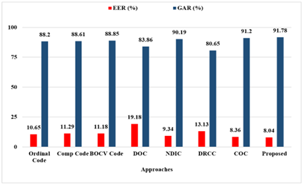
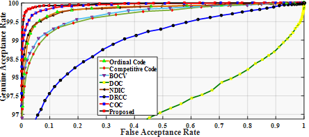
The obtained EER (%) and GAR (%) for the proposed approach is displayed in Table 2. and pictorially shown in Figure 3. The reported percentage of EER and GAR with this set up is 8.02 (%) and 91.71 (%), respectively. The efficacy of the proposed work can also be observed by ROC curves shown in Figure 4. It apparent from the ROC curve that the proposed approach is demonstrating the better performance compared to all listed approaches in Table 2. The experimental outcomes reveal that the proposed approach is the best among all listed approaches in the table.
Table 2. EER (%) comparison of proposed and existing approaches with IITD palmprint database
|
Approaches |
[12] |
[11] |
[14] |
[17] |
[20] |
[19] |
[21] |
Proposed |
|
EER |
10.65 |
11.29 |
11.18 |
19.18 |
9.34 |
13.13 |
8.36 |
8.04 |
|
GAR |
88.20 |
88.61 |
88.85 |
83.86 |
90.19 |
80.65 |
91.20 |
91.78 |
Figure 3. Bar chart representation of performance parameter comparison for the proposed Vs. existing recent approaches
Figure 4. Comparative performance for the proposed approach Vs. existing recent and popular approaches with IITD touchless database
Figure 5. Bar chart representation of performance parameter comparison for the proposed Vs. existing recent and popular approaches for PolyU 2D database
Table 3. EER (%) comparison of proposed and existing approaches with PolyU 2D palmprint database
|
Approaches |
[12] |
[11] |
[14] |
[17] |
[20] |
[19] |
[21] |
Proposed |
|
EER |
1.45 |
1.82 |
1.74 |
5.91 |
1.20 |
3.65 |
0.88 |
0.56 |
|
GAR |
98.51 |
98.12 |
98.46 |
94.06 |
98.81 |
96.53 |
99.14 |
99.35 |
Figure 6. Comparative performance of the proposed approach Vs. Existing approaches on PolyU 2D database
4.3 Performance with PolyU 2D database
In the evaluation and comparative analysis with PolyU 2D database, images of both sessions are employed. The experimentation process is divided into two stages. In first stage, the optimum parameters of the filter are derived using the images of first session.
Thereafter, performance of the proposed approach is derived using the filter bank tuned at optimum parameters and compared with existing state-of-the-art approaches. The different combinations of the α, β and c are explored for determining the optimum combination of the parameters. For this database, the optimum results were obtained at 9, 17 and 3 for α, β and c, respectively. The value of Pr, for this database is found optimum at 15%. Since palm line width within this database are thin as compared to IITD touchless database, it may be the possible reason behind the drop in the percentage of infirmity bits compared to IITD touchless database.
The experimental results of the proposed approach tuned to above experimental setup and images of the second session are tabulated in Table 3. and graphically represented in Figure 5. These results reveal that the proposed approach outperforms and displays EER of 0.56% and GAR of 99.35% which is the best among all methods reported in the Table 3. The method demonstrates lowest equal error rate which may be due to the constrained capturing environment with uniform lighting conditions. The corresponding ROC curves on PolyU 2D database, for both existing and proposed approach are shown in Figure 6, which confirms the effectiveness of the proposed scheme by outperforming the reported ones.
The most of the work in the literature considers palm lines as straight line. However, these are the curved. Thus, A novel curvilinear anisotropic filter-based coding approach, CDCI has proposed which considers curved palm lines of the palmprint. The proposed curvilinear anisotropic filter based CDCI representation employs fusion of two different binary representation, i.e., differential concavity and infirmity codes for palmprint representation. The reported performance of the proposed approach (in terms of Equal Error Rate) with touchless database is 8.04% which is 3.82% from the other curvature-based approach. In contrast, the reported error rate on contact-based database was found to be 0.56%, which is found to be the lowest among the all considered for this study and demonstrates 36.36% of improvement from the other curvature-based approach. approaches. In future, the proposed approach can be investigated with Neural Network and machine learning based approaches. Moreover, the method can be tested with more contact-based datasets.
[1] Shu, W., Zhang, D. (1998). Palmprint verification: An implementation of biometric technology. In Proceedings. Fourteenth International Conference on Pattern Recognition (Cat. No. 98EX170), IEEE, 1: 219-221. https://doi.org/10.1109/ICPR.1998.711120
[2] Lee, T.S. (1996). Image representation using 2D Gabor wavelets. IEEE Transactions on Pattern Analysis and Machine Intelligence, 18(10): 959-971. https://doi.org/10.1109/34.541406
[3] Yao, P., Li, J., Ye, X., Zhuang, Z., Li, B. (2006). Iris recognition algorithm using modified log-gabor filters. In 18th International Conference on Pattern Recognition (ICPR'06), IEEE, 4: 461-464. https://doi.org/10.1109/ICPR.2006.726
[4] Zhang, D., Kong, W.K., You, J., Wong, M. (2003). Online palmprint identification. IEEE Transactions on Pattern Analysis and Machine Intelligence, 25(9): 1041-1050. https://doi.org/10.1109/TPAMI.2003.1227981
[5] Kong, A., Zhang, D., Kamel, M. (2009). A survey of palmprint recognition. Pattern Recognition, 42(7): 1408-1418. https://doi.org/10.1016/j.patcog.2009.01.018
[6] Badrinath, G.S., Gupta, P. (2012). Palmprint based recognition system using phase-difference information. Future Generation Computer Systems, 28(1): 287-305. https://doi.org/10.1016/j.future.2010.11.029
[7] Prasad, S.M., Govindan, V.K., Sathidevi, P.S. (2011). Palmprint authentication using fusion of wavelet and contourlet features. Security and Communication Networks, 4(5): 577-590. https://doi.org/10.1002/sec.234
[8] Li, W., Zhang, D., Xu, Z. (2002). Palmprint identification by Fourier transform. International Journal of Pattern Recognition and Artificial Intelligence, 16(04): 417-432. https://doi.org/10.1142/S0218001402001757
[9] Dubey, P., Kanumuri, T., Vyas, R. (2018). Sequency codes for palmprint recognition. Signal, Image and Video Processing, 12: 677-684. https://doi.org/10.1007/s11760-017-1207-3
[10] Kong, A.W.K., Zhang, D. (2004). Feature-level fusion for effective palmprint authentication. In International Conference on Biometric Authentication, Berlin, Heidelberg: Springer Berlin Heidelberg, pp. 761-767. https://doi.org/10.1007/978-3-540-25948-0_103
[11] Kong, A.K., Zhang, D. (2004). Competitive coding scheme for palmprint verification. In Proceedings of the 17th International Conference on Pattern Recognition, 2004. IEEE, 1: 520-523. https://doi.org/10.1109/ICPR.2004.1334184
[12] Sun, Z., Tan, T., Wang, Y., Li, S.Z. (2005). Ordinal palmprint representation for personal identification [represention read representation]. In Proceedings of the IEEE Conference on Computer Vision and Pattern Recognition (CVPR’05), 1: 279-284. https://doi.org/10.1109/CVPR.2005.267
[13] Jia, W., Huang, D.S., Zhang, D. (2008). Palmprint verification based on robust line orientation code. Pattern Recognition, 41(5): 1504-1513. https://doi.org/10.1016/j.patcog.2007.10.011
[14] Guo, Z., Zhang, D., Zhang, L., Zuo, W. (2009). Palmprint verification using binary orientation co-occurrence vector. Pattern Recognition Letters, 30(13): 1219-1227. https://doi.org/10.1016/j.patrec.2009.05.010
[15] Zhang, L., Li, H., Niu, J. (2012). Fragile bits in palmprint recognition. IEEE Signal Processing Letters, 19(10): 663-666. https://doi.org/10.1109/LSP.2012.2211589
[16] Tamrakar, D., Khanna, P. (2015). Palmprint verification with XOR-SUM code. Signal, Image and Video Processing, 9(3): 535-542. https://doi.org/10.1007/s11760-013-0475-9
[17] Fei, L., Xu, Y., Tang, W., Zhang, D. (2016). Double-orientation code and nonlinear matching scheme for palmprint recognition. Pattern Recognition, 49: 89-101. https://doi.org/10.1016/j.patcog.2015.08.001
[18] Fei, L., Xu, Y., Zhang, D. (2016). Half-orientation extraction of palmprint features. Pattern Recognition Letters, 69: 35-41. https://doi.org/10.1016/j.patrec.2015.10.003
[19] Xu, Y., Fei, L., Wen, J., Zhang, D. (2016). Discriminative and robust competitive code for palmprint recognition. IEEE Transactions on Systems, Man, and Cybernetics: Systems, 48(2): 232-241. https://doi.org/10.1109/TSMC.2016.2597291
[20] Fei, L., Zhang, B., Xu, Y., Yan, L. (2016). Palmprint recognition using neighboring direction indicator. IEEE Transactions on Human-Machine Systems, 46(6): 787-798. https://doi.org/10.1109/THMS.2016.2586474
[21] Tabejamaat, M., Mousavi, A. (2017). Concavity-orientation coding for palmprint recognition. Multimedia Tools and Applications, 76: 9387-9403. https://doi.org/10.1007/s11042-016-3544-6
[22] Li, H., Zhang, J., Wang, L. (2014). Robust palmprint identification based on directional representations and compressed sensing. Multimedia Tools and Applications, 70: 2331-2345. https://doi.org/10.1007/s11042-012-1240-8
[23] Liu, J.L., Feng, D.Z. (2014). Two-dimensional multi-pixel anisotropic Gaussian filter for edge-line segment (ELS) detection. Image and Vision Computing, 32(1): 37-53. https://doi.org/10.1016/j.imavis.2013.12.001
[24] Hong Kong PolyU 2D /3D Database. https://www4.comp.polyu.edu.hk/~csajaykr/Database/3Dhand/Hand3DPose.htm.
[25] IITD Touchless Palmprint Database (version1.0). https://www4.comp.polyu.edu.hk/~csajaykr/IITD/Database_Palm.htm.
[26] Dubey, P., Kanumuri, T. (2015). Optimal local direction binary pattern based palmprint recognition. In 2015 2nd International Conference on Computing for Sustainable Global Development (INDIACom), Delhi, India, pp. 1979-1984.