Maryam Jebur Al-Sultan*![]() | Ali Al-Rifaie
| Ali Al-Rifaie![]()
© 2024 The authors. This article is published by IIETA and is licensed under the CC BY 4.0 license (http://creativecommons.org/licenses/by/4.0/).
OPEN ACCESS
The absence of specific guidelines to enhance the integrity of structural members to resist accidental loading such as impact, explosion and fire highly motivated the researchers to cover such a knowledge gap. In the current study, one of the most common structural members that used widely in structural frames named steel beams with large web openings (SBLWOs) was numerically investigated under impact load. Non-linear finite element (FE) models were created using ABAQUS software and validated against existing experimental data from the literature. The FE models developed considered the dynamic material properties in the elastic, plastic, and damage stage. Strain rate effect was also taking into account in the models. Afterwards, intensive parametric analyses of the parameters that affect the behavior of SBLWOs were performed including impact energy, impact location, and opening strengthening. The correlation outcomes of the FE and the experimental tests were in a good agreement in terms of force and displacement time histories and failure modes. The results showed that the SBLWOs were able to resist the impact with higher velocity rather than higher mass. Regarding the effect of impact location, the worst case was found to be when a cellular steel beam impacted close to the supports. Finally, the contribution of providing steel stiffeners in the impact zone resulted in a significant improvement in the shear and web buckling resistance.
dynamic response, finite element method, impact load, parametric analysis, large web openings
The capacity of structural members to resist the static gravity loading has been widely investigated. Such studies then crowned by providing different guidelines in which structural engineers were able to design such members to resist different types of static loading. These guidelines were used to design a building in London called “Ronan point” of 22 storey which its construction completed in 1968. A gas leak in one of the high floors led to an explosion that resulted in a wall failure of an apartment, which in turn supported the walls above. The absence of the supports of such walls led to a collapse of the floors above producing high impact force that cannot be resisted by the floors below. However, all floors were then smashed and progressive collapse was developed until it reached the ground floor [1].
An update to the existed regulations were adopted by civil engineers to minimise or avoid progressive collapse in the design process as an attempt to avoid causalities and to enhance the structural integrity of a structure. Thus, structural integrity was added as a key requirement to prevent such type of collapse. These modifications were not totally helpful to enhance the building resistance against progressive collapse particularly with the exposure of buildings to terrorist attacks. Later, more buildings were destroyed such as World Trade Centre in (USA 2001), (bomb of Madrid, 2004) and (Mumbai terrorist attack, 2008) due to progressive collapse failure.
In order to enhance the existed guidelines to resist impact and explosions, different studies were carried out in the aim of understanding the behaviour of different structural members under such loads including columns, slabs and beam column connections [2-11]. The share of beams to resist impact load is higher than slabs and connection, particularly with frames with strong connection-weak beam concept. Therefore, in the last decade, some attention was paid to investigate the steel beam response to impact load. Some beams named steel beams with large web openings (SBLWOs) often should be cut in the web zone to provide an appropriate access to the services to pass through such as duct, sewage pipes and electrical conduits. In spite of their advantages in providing light weight structures, higher flexibility and floor height reduction, SBLWOs have less shear and flexural capacity than those without openings.
As an action to understand the behavior of such beams under high loading rate, different theoretical and practical studies were conducted last decade to show how such beams reacted to dynamic loads. Steel beams with rectangular web openings were the focus of a numerical analysis conducted by Srivastava et al. [12]. It was found that the shape of the web opening has a minor effect on the natural frequency. El-Dehemy [13] analyzed the stress and deflection patterns of steel beams with web openings (SBWOs). The results showed that the deflection value of the steel beam increased as the number of openings increased. Beam stiffness also reduced due to openings when comparing SBWOs to bare steel beams. These findings are consistent with those by Jichkar et al. [14]. Al-Hussainy et al. [15] employed finite element (FE) methods to study how impact load might affect steel beams having circular openings. Parametric studies were performed to examine the effect of number of openings, impact energy, and impact location. The numerical results showed that providing openings reduced the contact impact force and increased the displacement. Yet, the flexural impact capacity was not dramatically altered by varying the number of openings. The flexural impact strength was studied by Al-Rifaie et al. [16] for steel beams with rectangular web openings. ABAQUS was used to generate 3D nonlinear FE models that were then used to study the effect of different impact velocities (2.214-7) m/s on the area, depth, number, and reinforcing of web openings. It has been found the opening depth has a little effect on the impact bending response of the steel beams. Whilst, reinforcing openings with horizontal steel stiffeners significantly improve impact bending capacity.
The examination is ongoing, and the subject of impact continues to preoccupy the vast majority of scholars in the field. Steel beams with hexagonal web openings (SBHWOs) were experimentally and numerically investigated by Wang et al. [17]. Results showed that peak force, displacement, and impact duration all increased at a rate proportional to the square of the impact energy. The maximum impact force was raised by increasing the opening spacing corresponding to a reduction in the impact duration, web-post buckling, and post-impact displacement. The maximum impact force and the average plateau impact force reduced using larger openings size, whereas the impact duration, web-post buckling, and post-impact displacement were all increased. Luo et al. [18] performed a numerical investigation on the dynamic stresses produced on castellated steel beams under impact load. The research was conducted on a number of variables including impact velocity, impact mass, opening spacing, opening height, beam height, impact location, span-to-height ratio, and boundary conditions. The results showed that both the impact velocity and mass affected the deflection of such beams and the time required to dissipate the impact energy. It was also discovered that the opening depth to beam height ratio had a slight effect on the deflection. Deflection curves were found to significantly affected by the location of impact.
From the above literature, it could be noticed that more studies are required for more understanding of the impact response of SBLWOs. The dynamic shear and moment capacity of such beams still unclear. However, the objectives of the current study could be as follows:
Success in achieving such objectives will contribute in more understanding of the methods of simulating SBLWOs under impact load. Also, it will assist to enhance the knowledge in terms of shear capacity, moment capacity and failure modes of such beams under impact load.
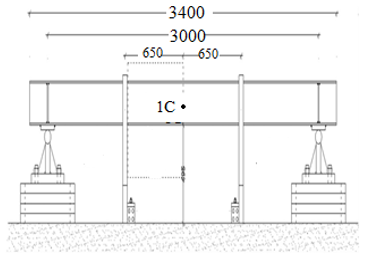
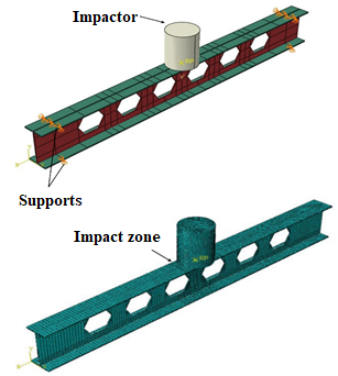
Two different experimental study results were used to validate the created FE models. The first study was carried out by D’Antimo et al. [19], while the second was carried out by Wang et al. [17]. The beams in both aforementioned studies were tested under drop weight impact. The applied mass and velocity details of D’Antimo et al. study is listed in Table 1. Trial tests were conducted using IPE 220 (220×110×5.9) mm grade S275 to support steel beams. The first specimen was subjected to a total of six multiple impacts, while the second specimen was only subjected to three. Two heights of impact of 250 and 500 mm and two masses of 211 and 460 kg were used to apply different velocities and impact energy. The experimental setup and instruments utilized are depicted in Figure 1. The steel web and flange plates properties are summarized briefly in Table 2. The results showed when strain rate was ignored, displacements were overstated and forces were underestimated. The US Department of Defense's dynamic increase factors (DIFs) levels also didn't match European steel grades. This was determined by comparing the American Society for Testing and Materials DIFs to the results presented by Hoffmann et al. [20]. Thus, the Johnson-Cook and Cowper-Symonds models successfully predicted peak force and displacement.
Table 1. Mass and velocity applied on samples in the D’Antimo et al. [19] study
|
Specimen No. |
Mass (kg) |
Height (mm) |
|
1 |
211 |
250 |
|
2 |
211 |
500 |
|
3 |
460 |
250 |
|
4 |
460 |
500 |
Table 2. Steel characteristics [21]
|
Component |
Modulus of Elasticity (GPa) |
Yield Stress (MPa) |
Ultimate Stress (MPa) |
|
Stiffener |
221.1 |
399.9 |
530.6 |
|
Flange |
189.3 |
356.8 |
526.9 |
|
Web |
220.4 |
390.1 |
527.0 |
Figure 1. The experimental test apparatus used by D’Antimo et al. [20]
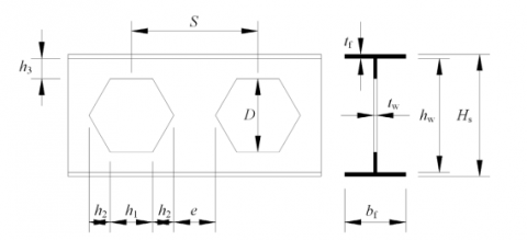
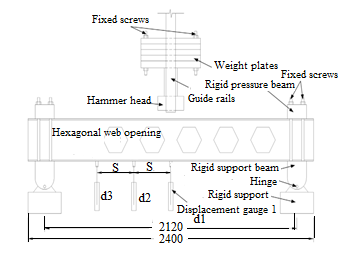
The FE models built in the current study were also verified against the experimental tests carried out by Wang et al. [17]. Openings details can be seen in Figure 2. Table 3 shows the specimen details and applied mass and velocity for each sample. The steel web and flange plates properties are summarized briefly in Table 4. Test setup and instrumentation used in the aforementioned study can be seen in Figure 3. The displacement gauge was only mounted on the left side of the SBHWOs because projected impact-induced deformations on both sides are the same. It was noticed that increasing impact energy resulted in an increase in the peak force, displacement, and impact duration. With increasing the spacing amongst openings, the maximum impact force increased, while the impact duration, web-post buckling, and post-impact displacement reduced. Maximum impact force and averaged plateau impact force decreased with increasing opening height, but impact duration, web-post buckling, and post-impact displacement increased.
Figure 2. Details of web openings in the Wang et al. [17] study
Table 3. Specimen details and applied mass and velocity used in the Wang et al. study [17]
|
Specimen No. |
Depth (mm) |
Mass (kg) |
Velocity (m/s) |
Energy (kJ) |
Spacing Between Openings (mm) |
ℎ11 (mm) |
ℎ22 (mm) |
|
1 |
180 |
430 |
10 |
21.5 |
310 |
104 |
52 |
|
2 |
180 |
430 |
10 |
16.5 |
310 |
104 |
52 |
|
3 |
180 |
430 |
10 |
21.5 |
290 |
104 |
52 |
|
4 |
200 |
430 |
10 |
21.5 |
310 |
116 |
58 |
Note: 1h1 and 2h2 stand for the opening sizes of the hexagonal web.
Table 4. Steel characteristics [17]
|
Component |
Elastic Modulus (GPa) |
Yield Strength (MPa) |
Ultimate Strength (MPa) |
Elongation (%) |
Average Thickness (mm) |
|
Flange |
200.36 |
329.49 |
464.5 |
39.37 |
9.29 |
|
Web |
199.47 |
304.43 |
442.88 |
40.84 |
7.33 |
Figure 3. The experimental test apparatus used by Wang et al. [17]
In order to perform the parametric study to investigate the key parameters, FE models should be first built and verified. Reference beams tested by D’Antimo et al. [19] and Wang et al. [17], as well as the scenarios chosen for beams with web openings under impact load, are simulated using the numerical techniques presented in this section. For this purpose, numerical models were developed in ABAQUS utilizing the explicit technique, which is more suited to modeling a dynamic process. This method would also help prevent convergence problems [21].
3.1 Boundary conditions and geometry
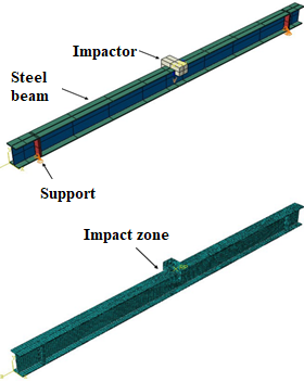
The boundary conditions and geometrical details of the FE models that were utilized in the two studies that are currently being discussed are presented in Figure 4. For the purposes of simulating simply supported situations, translational motions in the x and y directions were prevented. The impactor was modeled as a rigid body in the simulation, and all of its degrees of freedom were restricted, with the exception of its vertical motion (y-axis), which was left unrestricted so that vertical collisions could be occurred.
3.2 Element type, mesh size, and contact interactions
Due to its efficiency in impact modeling in term of accuracy and analysis time, eight-nodded solid elements with reduced integration (C3D8R) model were used. Geometrical and meshed models for used for FE verification can be seen in Figure 4. To find the optimal mesh size, a sensitivity analysis was conducted. Mesh sizes of 10 mm for the flange and the web near the middle band of the beam were found to produce close results to experimental tests with a favorable computation time. A rigid quadrilateral element (R3D4) with a 10 mm mesh size was used for impactor modeling. Tie restrictions were used to connect web to flange while surface-to-surface contact formulas were used to represent the interacting surfaces including contact between the impactor and beam to obtain the impact force. The tangential behavior of the contact described using a penalty friction formulation with a coefficient of friction of 0.2 between the contact surfaces, while the normal direction of contact was considered to be linear. The possibility of the more rigid part being the master surface and the less rigid part being the slave surface was also considered [22].
(a) Hoffmann et al. [20]
(b) Wang et al. [17]
Figure 4. Boundary conditions, geometry, and mesh
3.3 Steel material constitutive models
The elastic, plastic and damage stages were rigorously models based on the experimental results obtained. The strain rate effect was also considered. Dynamic performance analysis of structures and components requires an in-depth familiarity with the dynamic constitutive model of the underlying material [23, 24]. The Johnson-Cook (J-C) equation was used to determine the impact of strain rate.
$\sigma=\left[1+C \ln \varepsilon^*\right]$ (1)
where, σ is flow stress and C is the coefficient of strain rate hardening is a material constant that describes the behavior of a material under stress. $\varepsilon^*$ is the comparable strain rate to the reference strain rate ratio. It takes a series of numerical simulations with different combinations of material characteristics to discover the one that best matches the experimental data. C=0.038 have both been verified to work in the J-C equation. In addition, the triaxial stress-fracture stress connection for shear and ductile failure is illustrated in Tables 5 and 6 and is the basis for the steel fracture model used to simulate beam damage based on the research of Al-Thairy [25].
Table 5. The parameters of the numerical model for the material ductile failure [25]
|
Plastic Strain at Damage Initiation |
Maximum Triaxial Stress |
The Maximum Rate of Strain (sce-1) |
$\varepsilon_f^{p l}{ }_1$ |
$u_f^{p l_2}$ (mm) |
|
0.115 |
0.7 |
14.2 |
0.145 |
1.45 |
Note: 1 $\varepsilon_f^{p l}$ : The comparable plastic strain at the element full failure, 2 $u_f^{p l_2}$ The total plastic displacement at the failure point.
Table 6. The parameters of the numerical model for the material shear failure [25]
|
Plastic Strain at Damage Initiation |
Maximum Shear Stress Ratio |
Maximum Rate of Strain (sce1) |
$\varepsilon_f^{p l}{ }_1$ |
$u_f^{p l_2}$ (mm) |
|
0.172 |
1.8 |
120 |
0.83 |
8.3 |
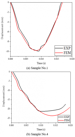
Figure 5. Validation of FE displacement time histories against the experimental results of D’Antimo et al. [19]
3.4 Verification of FE models
The FE models built in the current study were compared to the experimental results of both experiments to assess their validity. In the first study, presented by D’Antimo et al. [19], FE models were validated against four experimental tests. The convergence of the experimental and numerical displacement-time histories is depicted in Figure 5. Among all four examples, the largest difference between the experimental and projected displacements was less than 11 %, which was for sample No. 4. This may be attributed to the assumption of rigid impactor rather than steel one used in the tests. Besides, this assumption will slightly result in higher peak force in the FE models, which should be considered in the analysis of results obtained in the current study.
Figure 6. Validation of FE displacement time histories against the experimental results obtained by Wang et al. [17]
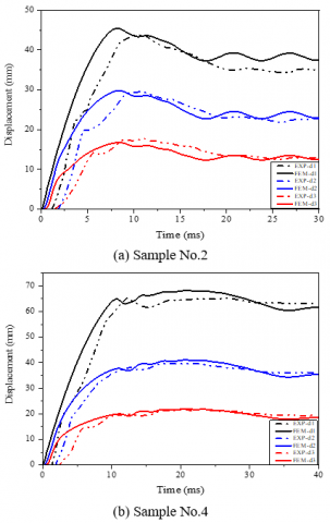
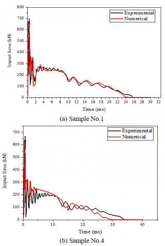
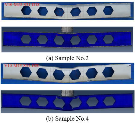
In the second investigation, by Wang et al. [17], FE models were validated against four experimental checks, as presented in the report FE modelling of SBWOs under impact load [26]. Figure 6 shows that the FE numerical simulation results were nearly in agreement with the experimental results in terms of displacement, and Figure 7 shows that the FE numerical simulation results were likewise in accord with the experimental study in terms of impact force. The failure of FE models agreed well with the experimental results detection, as illustrated in Figure 8. In addition, this small difference does not detract from the fact that the proposed FE model was able to account for the entire response of the selected samples. The discrepancy between the experimental and numerical results could be due to a number of variables. A possible explanation for the discrepancy between FE and experimental results is that the dropped hammer was considered a rigid body in the simulations and so did not exhibit any deformation or other causes. This research offered a FE model that was found to be in reasonable agreement with experimental data. The created FE model is then used to undertake a parametric investigation of the parameters influencing the behavior of the evaluated beams.
Figure 7. Validation of FE Impact force time histories against the experimental results obtained by Wang et al. [17]
Figure 8. Comparison of the deformation shape between the experimental test [17] and the numerical simulation
The previously detailed validated FE models were employed for further assessment of the critical parameters that effect the impact behavior of SBLWOs. Impact energy, impact location, and opening strengthening were selected for investigation in the current study. The cases selected are tabulated in Table 7.
Table 7. Summary of details of the parametric study
|
No. |
Designation |
Mass (kg) |
Velocity (m/s) |
Impact Energy (J) |
Distance from Mid Span (mm) |
Area (mm2) |
|
1 |
M1 |
150 |
16.931 |
21,500 |
0 |
28,080 |
|
2 |
M2 |
300 |
11.972 |
21,500 |
0 |
28,080 |
|
3 |
M3 |
430 |
10 |
21,500 |
0 |
28,080 |
|
4 |
M4 |
550 |
8.842 |
21,500 |
0 |
28,080 |
|
5 |
P1 |
430 |
10 |
21,500 |
0 |
28,080 |
|
6 |
P2 |
430 |
10 |
21,500 |
155 |
28,080 |
|
7 |
P3 |
430 |
10 |
21,500 |
310 |
28,080 |
|
8 |
P4 |
430 |
10 |
21,500 |
465 |
28,080 |
|
9 |
P5 |
430 |
10 |
21,500 |
620 |
28,080 |
|
10 |
P6 |
430 |
10 |
21,500 |
775 |
28,080 |
4.1 Impact energy
Multiple values of impact velocity and mass were used to examine the effect of impact energy (IE) on the behavior of SBLWOs under impact loading. The mass range of the impactor was from 150 to 550 kg, while the velocity range was from 8.842 to 16.931 m/s. Table 7 shows the cases investigated in the current study and Eq. (2) was used to obtain the impact energy for any given impact velocity (V) and landing mass (m):
$I E=\frac{1}{2} m V^2$ (2)
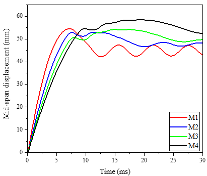
The numerical findings indicated in Figure 9(a) shows that both the maximum displacement and the associated time rise with increasing mass and decreasing impact velocity. It could be concluded that the maximum displacement is mainly controlled by impact mass rather than corresponding velocity. However, higher impact capacity could be obtained by applying higher velocity rather than impacting the SBLWOs with higher mass, and thus this finding may be related to the effect of the strain rate (the existence of the strain rate will raise the resistance of the section). This would be the case since a faster velocity led to a larger strain rate. These findings agreed with those of Wang [27], Al-Thairy [25], and Al-Rifaie [28].
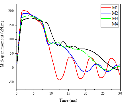
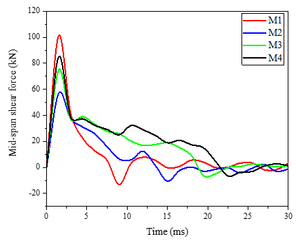
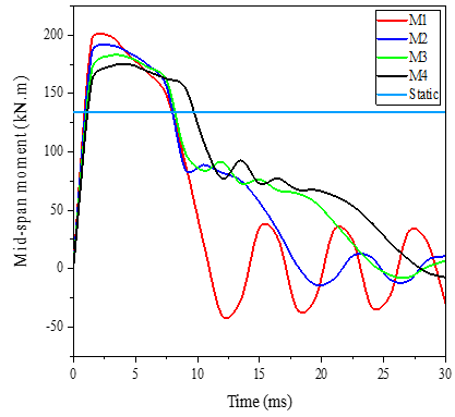
As can be seen in Figure 9(b), varying the mass from 150 to 550 kg resulted in a slight decrease in the mid-span moment from 199 to 175 kN.m, with an increase in time from the moment with a mass of 150 kg and a velocity of 16.931 m/s, while the impact energy remained constant and the velocity is variable. Shear force at the span midpoint was also studied to see how impact energy affected it (Figure 9(c)). A reduction in velocity from 16.931 to 11.972 m/s resulted in a shear force reduction of 44 %. While higher shear forces were produced in the plateau stage with the aforementioned decrease in the impact velocity (Again, the plateau force is more visible with higher impact mass). This demonstrates how the impact energy substantially affects the shear force applied midspan. The buckling was significantly affected by applying heavier mass than higher velocity. However, when the share of the top flange to dissipate energy is slight, the web significantly contributed to energy dissipation leading to higher buckling deformation. However, for model M4, it was noticed that the top and bottom flange contribution in energy dissipation was higher than other cases studied, which resulted in lower web buckling. It was found that most of the energy (more than 50% of the total plastic dissipated energy) was dissipated in the web.
(a) Mid-span displacement
(b) Mid-span moment
(c) Mid-span shear force
Figure 9. Effect of impact energy
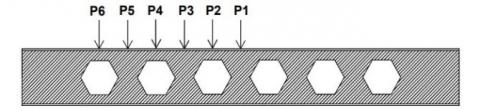
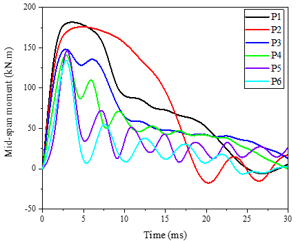
4.2 Impact location
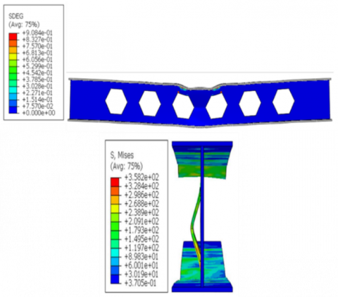
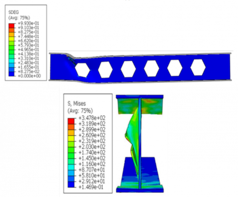
As the structures might be impacted in different locations, the validated FE models were employed to investigate impacting the SBLWOs in different locations. However, As, six different locations were used for such purpose as shown in Figure 10. In general, it was noticed that the maximum moment decreased as the impact location moved away from the mid span towards the supports as shown in Figure 11. Local and buckling failure were observed in the samples numerically tested. Both of them were located underneath the impactor. Further, greater deformation was observed when the impact location moved closer to the support as shown in Figure 12. The shear force time histories were also obtained from the FE models. Higher shear forces produced when the contact between impactor and the beam occurred. Then, fluctuated results of shear forces were obtained. It can be observed from the shear and moment time histories that the ratio of moment to shear (M/V).
Figure 10. Positioning of where impacts will occur
Figure 11. Effect of impact location
4.3 Effect of reinforcement of openings
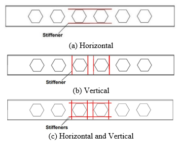
Reinforcement was added in a variety of designs at the openings and in the solid section of the web to increase the web strength and reduce the stress concentration there. Having the same resistance as the complete web beam is the goal of stiffeners, even though local buckling of the opening plates can be minimized or relieved by permitting full development of the plastic mechanism surrounding the opening. Three forms of stiffeners (horizontal stiffening, vertical stiffening, horizontal and vertical stiffening together; see Figure 13) were tested in numerical simulations to determine their impact on the overall structure efficiency. The stiffeners were designed using the geometrical properties, and the determinants were calculated from the European code [29]. Given that the thickness of the stiffener does not exceed the thickness of the web.
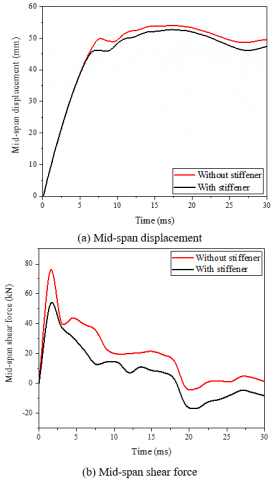
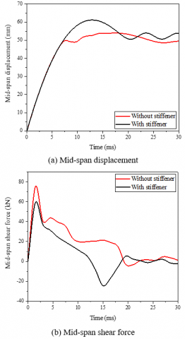
The results, given in Figure 14 showed that the displacement is reduced when utilizing horizontal stiffeners by 2.4% compared to beams without reinforcement and that the shear force at mid-span is reduced by 30%. This is because the horizontal reinforcement lessens the potential for an extra moment (Vierendeel moment) that arises as a result of the transmission of shear through the openings. Hence, the reinforcement transfers and distributes this stress to the steel cross-section of the beam on the left and right sides of the opening. This is something also shown by Al-Rifaie [16].
(a) P1
(b) P6
Figure 12. Effect of varying impact locations on failure
Figure 13. Different types of web openings stiffener
Figure 14. Effect of the horizontal stiffener
Figure 15. Effect of the vertical stiffener
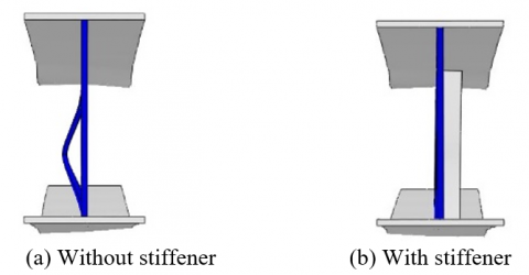
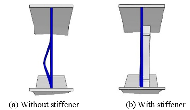
Figure 16. The failure mode of SBHWOs with and without the vertical stiffeners at the impact zone
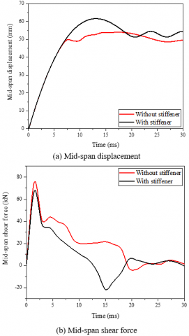
Vertical reinforcement, which increases pressure concentration along the openings and bends the web plate, causes a greater deflection. As can be seen in Figure 15, increasing the strength of the web solid section reduces the shear force through the openings, but this results in a larger deflection due to the stresses being greater through the opening than in the solid part. These results are consistent with those of Anupriya and Jagadeesan [30]. This is due to the fact that the stresses on the opening are higher than those on the solid part, so the strengthening of the opening fixes the failure of the Vierendeel and also plays a significant role in addressing web buckling. Figure 16 shows how the buckling in the web is completely treated by the addition of vertical stiffeners. Although it would only slightly reduce the perforated section capacity, stress accumulation around the web opening could cause it to fail early.
The obtained deformation modes under impact load were almost identical to those under static load involving Vierendeel failure, post-web buckling, and shear buckling but with the appearance of high local failure near the impact zone.
The use of stiffeners enables better stress redistribution along the web openings which leads to an increase in the beams load-carrying capacity. Thus, the use of both horizontal and vertical stiffeners together increases the strength of the structure. Figure 17(b) displays a 21.4% reduction in shear force at the span's center, indicating that the horizontal and vertical stiffening significantly affect the shear force. Figure 17(a) demonstrates how this type of reinforcement increased the displacement in the center of the span. As can be seen in Figure 18, the stiffening function not only helped to resolve the local failure but also effectively handled the web buckling failure. It is evident that the increase in displacement and moment as a result of the employment of each type of reinforcement (vertical, horizontal and vertical together) is nearly equal. This can be seen by looking at the figures. Because of this, the third kind, which refers to the horizontal and vertical reinforcement together, can be recommended as the type to employ because it is an effective type in treating buckling as well as external deformations of the opening angles.
Figure 17. Effect of the vertical and horizontal stiffeners
Figure 18. The failure mode of SBHWOs with and without the vertical and horizontal stiffeners at the impact zone
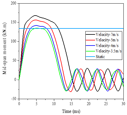
Figure 19. Static moment capacity vs impact moment capacity with different impact velocities
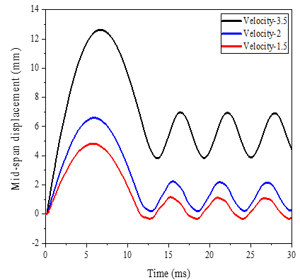
Figure 20. Displacement-time traces at mid-span of SBHWOs with different velocities
Some researchers, such as Shaker and Shahat [31], have suggested using the first type of stiffening (horizontal stiffening) when the load is static because it is more cost-effective than the third type (horizontal and vertical stiffening together) and it effectively compensates for the loss of beam strength in the perforated section.
4.4 Comparison between impact and static capacity
In order to compare the static bending capacity with impact capacity, the formula adopted by the American code [32] was used as follows:
$M_m=M_p\left[1-\frac{\Delta A s\left(\frac{h_{\mathrm{o}}}{4}+e\right)}{z}\right]$ (3)
Mₘ: Maximum nominal bending capacity, Mₚ: Plastic bending capacity, ∆As: Net reduction in area of steel, ho: Depth of opening, Z: Plastic modulus, and e: Eccentricity of opening.
This effort began by iterating to find the critical velocity with identical moment capacity under static and impact loads. Figure 19 shows that the velocity was changed from 7 m/s to 3.5 m/s to reach the critical velocity. At this velocity (3.5 m/s), the beam still deforms. As seen in Figure 20, the persistent deformation vanishes at 1.5 m/s, suggesting that the beam has changed from plastic to elastic. However, the impact load was applied using the methods indicated in Section 4.1, which involved computing masses and velocities. The static moment capacity at the opening based on Eq. (3) was 134.21 kN.m, which can be compared to the dynamic moment in Figure 21. Compared to the static instant, the dynamic moment was 31%-48% bigger.
Figure 21. Static moment capacity vs impact moment capacity with different masses
In order to create a digital model of SBLWOs, this research utilized the FE program ABAQUS. Also, the numerical model was verified by comparing experimental and simulated outcomes. To do this, it ran a series of analyses to determine how various factors, such as impact energy (21500 J), impact locations (flexural and shear zone), and opening reinforcement (vertical, horizontal and both), affected the final result. Some of the findings are as follows:
- Results from trials on steel beams subjected to impact load demonstrated good agreement with the FE model described here in terms of failure mode and displacement as well as the impact force.
-More deformation, including local failure or/and web buckling would be obtained by applying higher mass and lower velocity. However, it is recommended to consider this in the predicting an equivalent static force to estimate the impact capacity of SBLWOs. It is recommended to investigate the effect of impact impulse and momentum using similar energies for more understanding of the impact response of SBLWOs.
- The internal moment curve of the SBLWOs was greatly affected by changing the impact location. The maximum moment was reduced when the impact point shifted from the middle of the span to the end support, while the maximum shear force first decreased and then increased. This meant that the deformations increased as the point of impact got closer to the support. However, the worst case that should be taken to design SBLWOs may be considered assuming the impact load location is located in the shear zone. As the impact may be applied in different directions. It is recommended to investigate the response of SBLWOs under oblique impact.
- The strengthening of SBLWOs using horizonal and vertical stiffeners together considerably improved the dynamic moment and shear capacity. The need for a novel reinforcement configuration to resist impact load still required. Also, the contribution that concrete slab in composite beams to enhance impact capacity is of note to be studied.
- Comparing the impact results with static results showed that impact moment was larger by a range of (31%) to (48%) than the static moment. This may give a preliminary indication on the dynamic increase factor that could be used to propose an equivalent static force. More investigations are required to assist in proposing dynamic increase factors and equivalent static force.
- Finally, the modest design guidelines adopted to design structures under accidental loads, which is limited to perform a dynamic analysis, should be enhanced by valuable studies to present a detailed design guideline. The current study provided a comprehensive knowledge on the key parameters that affect the impact response of SBLWOs and may help in proposing a design formula to predict the impact capacity of SBLWOs.
The authors would like to thank all those who supported and pushed this work to be achieved represented by the Dean and lecturers of College of Engineering in Al-Muthanna University.
|
C |
the coefficient of strain rate hardening is a material constant that describes the behavior of a material under stress |
|
h1, h2 |
the opening sizes of the hexagonal web, mm |
|
ho |
depth of opening, mm |
|
IE |
impact energy |
|
m |
impact mass, kg |
|
M1, M2, M3, M4 |
numbers of the impact energy |
|
Mₘ |
maximum nominal bending capacity at the location of an opening, kN.m |
|
Mₚ |
plastic bending capacity of an unperforated steel beam, kN.m |
|
P1, P2, P3, P4, P5, P6 |
numbers of the impact locations, mm |
|
V |
impact velocity, m/s |
|
Z |
plastic section modulus of member without opening, mm3 |
|
e |
eccentricity of opening, mm |
|
Greek symbols |
|
|
σ |
flow stress, N/m2 |
|
$\varepsilon^*$ |
strain rate, s-1 |
|
$\varepsilon_{\mathrm{f}}^{\mathrm{pl}}$ |
the comparable plastic strain at the element's full failure |
|
$\mathrm{u}_{\mathrm{f}}^{\mathrm{pl}}$ |
the total plastic displacement at the failure point, mm |
|
∆As |
net reduction in area of steel section due to presence of an opening, mm2 |
[1] Pearson, C., Delatte, N. (2005). Ronan point apartment tower collapse and its effect on building codes. Journal of Performance of Constructed Facilities, 19(2): 172-177. https://doi.org/10.1061/(ASCE)0887-3828(2005)19:2(172)
[2] Lu, Y., Hao, H., Ma, G., Zhou, Y. (2001). Simulation of structural response under high-frequency ground excitation. Earthquake Engineering & Structural Dynamics, 30(3): 307-325. https://doi.org/10.1002/eqe.8
[3] Santiago, A., Simoes da Silva, L., Vaz, G., Vila Real, P., Gameiro, L.A. (2008). Experimental investigation of the behaviour of a steel sub-frame under a natural fire. Steel and Composite Structures, 8(3): 243-264. https://doi.org/10.12989/scs.2008.8.3.243
[4] Huo, J., Zhang, J., Liu, Y., Fu, F. (2017). Dynamic behaviour and catenary action of axially-restrained steel beam under impact loading. Structures, 11: 84-96. https://doi.org/10.1016/j.istruc.2017.04.005
[5] Li, M., Zong, Z., Hao, H., Zhang, X., Lin, J., Xie, G. (2019). Experimental and numerical study on the behaviour of CFDST columns subjected to close-in blast loading. Engineering Structures, 185: 203-220. https://doi.org/10.1016/j.engstruct.2019.01.116
[6] Yang, B., Tan, K.H. (2013). Experimental tests of different types of bolted steel beam-column joints under a central-column-removal scenario. Engineering Structures, 54: 112-130. https://doi.org/10.1016/j.engstruct.2013.03.037
[7] Yang, B., Tan, K.H., Xiong, G. (2015). Behaviour of composite beam-column joints under a middle-column-removal scenario: Component-based modelling. Journal of Constructional Steel Research, 104: 137-154. https://doi.org/10.1016/j.jcsr.2014.10.003
[8] Ren, P., Li, Y., Lu, X., Guan, H., Zhou, Y. (2016). Experimental investigation of progressive collapse resistance of one-way reinforced concrete beam-slab substructures under a middle-column-removal scenario. Engineering Structures, 118: 28-40. https://doi.org/10.1016/j.engstruct.2016.03.051
[9] Tan, Z., Zhong, W., Tian, L., Zheng, Y., Meng, B., Duan, S. (2021). Numerical study on collapse-resistant performance of multi-story composite frames under a column removal scenario. Journal of Building Engineering, 44: 102957. https://doi.org/10.1016/j.jobe.2021.102957
[10] Zhao, Z., Liu, Y., Li, Y., Guan, H., Yang, Z., Ren, P., Xiao, Y. (2022). Experimental and numerical investigation of dynamic progressive collapse of reinforced concrete beam-column assemblies under a middle-column removal scenario. Structures, 38: 979-992. https://doi.org/10.1016/j.istruc.2022.02.050
[11] Jin, L., Lan, D., Zhang, R., Qian, K. (2023). Effect of fire on behavior of RC beam-column assembly under a middle column removal scenario. Journal of Building Engineering, 67: 105496. https://doi.org/10.1016/j.jobe.2022.105496
[12] Srivastava, M., Pallav, A., Maurya, K. (2017). Vibrational behaviour of steel beam with web openings under dynamic and fatigue loading. In 13th International Conference on Vibrational Problems Proceedings, Institute of Technology Guwahati, India, pp. 1-6.
[13] El-Dehemy, H. (2017). Static and dynamic analysis web opening of steel beams. World Journal of Engineering and Technology, 5(2): 275. https://doi.org/10.4236/wjet.2017.52022
[14] Jichkar, R.R., Arukia, N.S., Pachpor, P.D. (2014). Analysis of steel beam with web openings subjected to buckling load. International Journal of Engineering Research and Applications, 4(5): 185-188.
[15] Al-Husainy, A.S., Al-Rifaie, A., Ogaidi, W. (2020). Behaviour of steel beams with circular web openings under impact loading. IOP Conference Series: Materials Science and Engineering, 888(1): 12069. https://doi.org/10.1088/1757-899X/888/1/012069
[16] Al-Rifaie, A., Al-Husainy, A.S., Al-Mansoori, T., Shubbar, A. (2021). Flexural impact resistance of steel beams with rectangular web openings. Case Studies in Construction Materials, 14: e00509. https://doi.org/10.1016/j.cscm.2021.e00509
[17] Wang, F., Fu, C., Chen, H., Luo, C., Chen, Y. (2022). Effect of impact loading on the dynamic response of steel beams with hexagonal web opening. Thin-Walled Structures, 180: 109896. https://doi.org/10.1016/j.tws.2022.109896
[18] Luo, C., Wang, F., Chen, H., Chen, L., Fu, C., Chen, Y., Liao, Q. (2022). Castellated steel beams under impact load. Journal of Constructional Steel Research, 196: 107394. https://doi.org/10.1016/j.jcsr.2022.107394
[19] D’Antimo, M., Latour, M., Rizzano, G., Demonceau, J.-F. (2019). Experimental and numerical assessment of steel beams under impact loadings. Journal of Constructional Steel Research, 158: 230-247. https://doi.org/10.1016/j.jcsr.2019.03.029
[20] Hoffmann, N., Kuhlmann, U., Demonceau, J.-F., Jaspart, J.-P., Colomer, C., Hoffmeister, B., Zandonini, R., Hjiaj, M., Mohler, C. (2015). Robust impact design of steel and composite buildings. IABSE Symposium Report, International Association for Bridge and Structural Engineering, 2015: 38-45.
[21] Cho, S.-R., Truong, D.D., Shin, H.K. (2014). Repeated lateral impacts on steel beams at room and sub-zero temperatures. International Journal of Impact Engineering, 72: 75-84. https://doi.org/10.1016/j.ijimpeng.2014.05.010
[22] Dassault Systèmes. (2010). Abaqus Analysis User’s Manual. Providence, RI: Dassault Systèmes Simulia Corp.
[23] Jones, N. (2011). Structural Impact. Cambridge University Press.
[24] Johnson, G.R., Cook, W.H. (1985). Fracture characteristics of three metals subjected to various strains, strain rates, temperatures and pressures. Engineering Fracture Mechanics, 21(1): 31-48. https://doi.org/10.1016/0013-7944(85)90052-9
[25] Al-Thairy, H.A., Wang, Y. (2014). Behaviour and design of steel columns subjected to vehicle impact. Applied Mechanics and Materials, 566: 193-198. https://doi.org/10.4028/www.scientific.net/AMM.566.193
[26] Al-Sultan, M.J., Al-Rifaie, A. (2023). Finite element modelling of steel beams with web openings under impact load. Muthanna Journal of Engineering and Technology (MJET), 11(1): 16-25.
[27] Wang, H., Yang, B., Zhou, X.H., Kang, S.B. (2016). Numerical analyses on steel beams with fin-plate connections subjected to impact loads. Journal of Constructional Steel Research, 124: 101-112. https://doi.org/10.1016/j.jcsr.2016.05.016
[28] Al-Rifaie, A.K. (2018). Lateral impact responses of steel end plate beam-to-column connections. The University of Liverpool (United Kingdom).
[29] Lawson, R. M., Hicks, S.J. (2011). Design of composite beams with large web openings: in accordance with Eurocodes and the UK National Annexes. Steel Construction Institute.
[30] Anupriya, B., Jagadeesan, K. (2014). Shear strength of castellated beam with and without stiffeners using FEA (ANSYS 14). International Journal of Engineering and Technology (IJET), 6(4): 1970-1981.
[31] Shaker, F., Shahat, M. (2015). Strengthening of web opening in non-compact steel girders. Journal of Mechanical and Civil Engineering. Ver. II, 12(5): 34-47. https://doi.org/10.9790/1684-12523447
[32] Steel_Design_Guide_Series_Steel_and_Comp-AISC.pdf.