Dmitry M. Borodulin![]() | Marina N. Oreshina
| Marina N. Oreshina![]() | Dmitry V. Sukhorukov*
| Dmitry V. Sukhorukov*![]() | Ilia B. Kazakov
| Ilia B. Kazakov![]()
© 2023 IIETA. This article is published by IIETA and is licensed under the CC BY 4.0 license (http://creativecommons.org/licenses/by/4.0/).
OPEN ACCESS
The goal of the present study was to enhance the homogeneity of mixtures produced in centrifugal mixers. Attention was devoted to the analysis of particle movements and interactions within the mix, with an intention to mitigate segregation phenomena and contribute to the refinement of mixer design. By understanding and predicting the behavior of medium components within the working chamber of the mixer, a qualitative improvement in the production of bulk mixtures can be achieved. A simulation was conducted of dry powder mixing at a ratio of 1:100 in a continuous centrifugal apparatus equipped with a disk-shaped rotor and a thin-walled truncated cone. LabVIEW software was employed to estimate the motion and velocity of particles within the rotor. Findings from the study provided a detailed portrayal of a material particle's trajectory within the mixer. Immediately upon entry into the apparatus, the particle's velocity on the rotor disk was observed to increase rapidly within an initial two-second period, followed by uneven acceleration. This inconsistency was attributed to the pulsating nature of the particle's motion, along with its shape and surface roughness. Near the rotor disk's periphery, more systematic movement was observed among particles of varying densities within the medium flow. From this study, differential equations were derived and a mathematical model was developed to illustrate changes in speed and trajectory of particles with different densities. The model aligns well with calculations from numerical methods, offering a high degree of accuracy for theoretical descriptions and calculations pertaining to bulk mixture production processes. Therefore, this study offers a significant tool for future improvements in the design and utilization of centrifugal mixers.
centrifugal mixer, differential equations, mixing, numerical methods, particle velocity
1.1 Background
The surge in urbanization, transformative lifestyle shifts, and heightened awareness of functional foods' health benefits are anticipated to catalyze the expansion of the functional food market in the foreseeable future. As postulated by the DISCOVERY Research Group, the Russian healthy food market is expected to amass a volume of 1 trillion rubles by 2023, while the global market is projected to grow at a more robust pace, reaching 17 trillion rubles by 2027 [1]. One of the most ubiquitous processes in functional food production is the mixing of bulk materials, with the primary challenge being the attainment of homogeneous granular mixtures in composition. This solution is invariably complicated by an array of concomitant difficulties stemming from a broad spectrum of changes in the physical and mechanical properties of processed materials, quality requirements, product composition, productivity, and the energy and metal consumption of equipment [2, 3].
1.2 Problem statement
Segregation, a negative outcome arising from the disparity in the physical and mechanical properties of the mixed components, is a predominant concern. Centrifugal mixers (CM) are most commonly employed in the mixing of bulk materials, attributed primarily to their simplistic design and low energy consumption. However, their efficiency in processing components susceptible to segregation is limited. The issue arises from the denser and finer particles being centralized in the mixture's circulation. The incorporation of additional elements that traverse the segregation center during the mixer rotor's rotation, thereby suppressing it, complicates the design of the apparatus, its manufacture, and maintenance, particularly for continuous mixers. Studying the movement and interaction of mixed components can significantly mitigate or entirely eradicate segregation, simplifying the process of mixer design enhancement [4, 5].
1.3 Literature review
The process of moving particles of mixed components within the working chamber of a centrifugal mixer can be modeled using the Navier-Stokes equation. This equation, in conjunction with the conservation of mass and energy, and the relation connecting pressure with internal energy and density (the equation of state), prescribes the motion of a continuous medium. The primary complication in solving the Navier-Stokes equation is the emergence of instability in the values characterizing the process at high Reynolds numbers [6, 7]. One of the most imperative issues in computational fluid dynamics is accounting for turbulence, the process of chaotic changes in velocity and pressure at various points in the flow. Direct modeling of turbulence (DNS) is seldom employed and limited to a narrow set of model cases due to its complexity. In the case of DNS, the cell size and the step time are determined by the Kolmogov scale, rendering the step too small and the mesh too fine for most practical problems. Nevertheless, due to its versatility, DNS is still utilized for certain types of calculations [8, 9]. The most prevalent models are those with averaged parameters characterizing turbulence (RANS-models), among which k-ε is the most renowned. Its initial mention is linked to the work of Harlow-Nakayama in 1968. The mass density (k) and the dissipation rate of turbulent energy (ε) are used as characterizing parameters. In its classical form, the model is primarily applicable to flows with a high Reynolds number without large longitudinal pressure gradients and eddy flows. Through certain modifications (RNG k-ε and Realizable k-ε), its applicability was extended to a broader class of flows [10-12]. The next most popular is the standard Wilcox k-ω model, which accounts for low-Reynolds effects, the influence of compressibility, and the development of shear flows quite well. In 1993, Menter proposed a combination of both strengths into a single model named “SST”. It is unique in behaving like k-ω in the near-wall zone and like k-ε far from the wall [13]. In the current study, differential equations have been derived and a mathematical model has been developed to depict the change in the velocity of material particles with different densities.
1.4 Objective of the study
The study's objective is to enhance the homogeneity of mixtures produced using a centrifugal mixer. To achieve this, it is imperative to investigate the movement and interaction of mixed components' particles. This will substantially reduce or completely eliminate the phenomenon of segregation, thereby simplifying the process of mixer design improvement.
In our research we developed the program “Velocity Calculation by Numerical Methods-Euler Method” in the LabVIEW graphical programming environment for calculating particle velocities in a centrifugal mixer. When conducting research, we used the LabVIEW program, which specializes in data collection and processing systems, as well as in the management of technical objects and technological processes. Ideologically, LabVIEW is very close to SCADA systems, but unlike them, it is more focused on solving problems not so much in the field of automated process control systems, but in the field of automated research systems. The LabVIEW graphical programming environment is aimed at engineers and does not require special knowledge in the field of programming training, this is its main advantage. Since engineers do not need to additionally involve programming specialists or learn new programming languages to solve modeling problems and find design parameters, LabVIEW is competitive with programs such as MathLab, MathCad and other popular data processing environments. In new versions of LabVIEW, in addition to the capabilities of the basic panels, there is a wide functionality of libraries, so that most mathematical problems can be solved by selecting the necessary blocks from the libraries.
The LabVIEW program consists of two parts:
Virtual instruments can be used as building blocks to build other virtual instruments. The front panel of the virtual instrument contains input-output means: buttons, switches, LEDs, verniers, scales, information boards, etc. They are used by a person to control the virtual instrument, as well as other virtual instruments for data exchange. The block diagram contains functional nodes that are sources, receivers, and means of data processing. Also, the components of the block diagram are terminals (“back contacts” of front panel objects) and control structures (which are analogues of such elements of textual programming languages as the conditional operator “IF”, loop operators “FOR” and “WHILE”, etc.). Functional nodes and terminals are combined into a single scheme by communication lines.
Equations based on the basic dependencies of mechanics, in particular the application of Newton’s laws, were used to model the motion of particles and the medium. Our methodology does not account for potential complexities or deviations in real-world applications. To simulate the movement of bulk material on the rotor disk inside a centrifugal mixer, consider the direction of movement of its individual particles in the horizontal plane [14, 15]. The components of the medium particle velocity vector are shown in Figure 1.
Figure 1. Direction of movement of a particle of material on the rotor disk
Figure 1 shows that at t=0 the particle is affected by pressure from other particles in such a way that the vector V0 is directed vertically.
At:
φ0=90°
V0у=V0
V0х=0
Δx=0
First step:
φ1-random number.
$V_{1 x}=V_{0 x}+\Delta V_{1 x}$ (1)
$\Delta V_{1 x}=\left(V_{0 x} e^{-\alpha t}{ }_1\right) \cos \varphi_1$ (2)
$V_{1 x}=V_1 \cos \varphi_1$ (3)
Second step:
φ2-random number
$V_{2 x}=V_{1 x}+\Delta V_{2 x}$ (4)
$\Delta V_{2 x}=\left(V_{1 x} e^{-\alpha t}{ }_2\right) \cos \varphi_2$ (5)
$V_{2 x}=V_2 \cos \varphi_2$ (6)
n-step:
φn-random number
$V_{n x}=V_{(n-1) x}+\Delta V_{n x}$ (7)
$\Delta V_{n x}=\left(V_{(n-1) x} e^{-\alpha t}{ }_n\right) \cos \varphi_n$ (8)
$V_{n x}=V_n \cos \varphi_n$ (9)
At Δt=1, the particle tends due to the centrifugal force from the center to the periphery of the housing. In the absence of structural obstacles, the particle moves from the center to the periphery of the housing in a relatively short time. In the opposite case, the velocity vector changes, more time is spent.
A particle in a centrifugal mixer is affected by the centrifugal force, the force of aerodynamic air resistance, the forces of frontal collision of particles, the force from the collision of particles with equipment elements. In view of the foregoing, based on Newton’s second law, the differential equation describing the change in particle velocity has the form:
$\frac{d V_i}{d t}=\frac{\left(F_{\text {gravity }}+F_{\text {center }}+F_{\text {particle collision }}+F_{\text {construc }}\right)}{m}$ (10)
In this case, the distance by which the particle has shifted from its zero value is determined by the equation:
$\frac{d s_i}{d t}=V_i$
When considering a unit volume, Eq. (10) takes the form:
$\frac{d V_i}{d t}=\frac{\left(P_{\text {gravity }}+P_{\text {center }}+P_{\text {particle collision }}+P_{\text {construc }}\right)}{\rho}$ (11)
where,
P-pressure, Pa;
ρ-particle density, kg/m3.
When the components of the mixture move in a centrifugal mixer, the directed flow of solid particles is carried away by air due to the action of centrifugal force and gravity, and acquires the properties of a liquid. That is, in fact, the movement of the fluidized bed is considered, therefore, in this case, it is advisable to consider the movement of the particle and the flow. The change in particle velocity Vi is described by Eq. (12), air velocity U is described by Eq. (13):
$\frac{d V_i}{d t}=\frac{\left(P_{\text {gravity }}+P_{\text {center }}+P_{\text {particle collision }}+P_{\text {construc }}\right)}{\rho}$ (12)
$\frac{d V_i}{d t}=\frac{\left(P_{\text {gravity }}+P_{\text {center }}+P_{\text {particle collision }}+P_{\text {construc }}\right)}{\rho_{\text {particle }}}$ (13)
The following expressions are the solution to the system of these equations:
$V_{\text {particle }}=\left(V_0-V_{0 \text { част }} \cdot e^{-\alpha t}\right) * K 1$ (14)
$U=\left(U_0-U_0 \cdot e^{-\alpha t}\right) * K 2$ (15)
where,
U0, V0-the initial particle velocities determined by the rotation of the rotor,
α-coefficient determined experimentally (in calculations, α=0.97 was taken),
K1, K2-coefficients, K1=3.32 was taken in the calculation (determined empirically).
The use of numerical methods allows us to consider changes in parameters at the current step as the sum of the value at the previous step and the increment of the parameter over time for the current step.
In this case, the projections of particle velocities Vx and Vy on the X and Y axes are considered by arbitrary setting of the angle φ:
$V_x=V \cdot \cos \varphi$ (16)
$V_y=V \cdot \sin \varphi$ (17)
Thus, the value of the particle velocities at the current step is determined by the sum of the velocity at the previous step and the velocity increment for Δt:
$V_{x i}=V_{x i-1}+\Delta V_{x i}$ (18)
$V_{y i}=V_{y i-1}+\Delta V_{y i}$ (19)
The values ΔVxi, ΔVyi show the impact on the particle velocity of collisions between particles and enclosing structures (elements of the rotor blades and the conical housing of a CM).
In this case, the distance to which the particle has moved due to a change in the velocity of movement during the time Δt relative to the X and Y axes is determined by the formulas:
$S_{x i}=S_{x i-1}+\Delta V_{x i} \cdot \Delta t$ (20)
$S_{y i}=S_{y i-1}+\Delta V_{y i} \cdot \Delta t$ (21)
The velocity of particles at the current step is determined by the formula:
$V_i=\sqrt{V_{x i}^2+V_{y i}^2}$ (22)
The adequacy of the calculations was checked in Excel program.
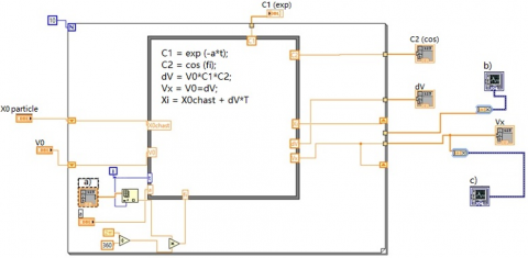
When conducting research, the Euler method was used because of its simplicity and high speed of finding a solution. The result of the studies presented above was the program “Velocity Calculation by Numerical Methods-Euler Method” developed in the LabVIEW graphical programming environment for calculating particle velocities in a centrifugal mixer (Figure 2). The particle moves from the center to the periphery of the CM rotor disk with increasing velocity during the first three seconds after entering the apparatus, then the particle velocity levels off.
On the graphs of Figure 3 shows the calculations of the particle velocities by the numerical method in Excel, the numerical method in LabVIEW and analytically (the exact calculated value according to the proposed expression, for solving the differential equation according to Eq. (8)).
Figure 2. Block diagram of a LabVIEW calculation program
Note: a) – Set angle Fi; b) – Distance change on X (relative to the original location on X); c) – Particle Vx speed
Figure 3. Graphs of particle velocity change
Note: 1-particle velocity calculated numerically in Excel; 2-particle velocity calculated by formula 11; 3-particle velocity calculated numerically in LabVIEW
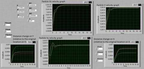
The convergence of the graphs shows that Eq. (14), proposed as a result of solving differential Eq. (12), is correct and can be used with a high degree of accuracy in calculations, a theoretical description of the production process of bulk mixtures. Calculations in the LabVIEW program using numerical Euler methods for the velocities of particles with different densities are shown in Figure 4.
Figure 4. The front panel of the program for calculating the velocities of particles with different densities using the Euler method in the LabVIEW program
From Figure 4, it can be seen that particles with a higher density have a higher acceleration during the first 6 seconds, then the velocity of the particle becomes constant. At the first stage, after the particle enters the apparatus, its velocity on the rotor disk rapidly increases within 2 seconds. The second stage (the next 4 seconds) is characterized by the appearance of zigzag sections on the graphs, showing the uneven acceleration of the particles of the flow, associated with the pulsating nature of their movement, as well as the shape and roughness. Particles during this period of time move more chaotically, separately, which proves their intersection on the rotor disk of the CM, hence the mixing process is carried out. Then, near the periphery of the rotor disk of the CM, the movement of particles with different densities is carried out more systematically in the flow. This reduces the influence of the factors described above on the fluctuations of their velocities. At the same time, the obtained curves on the graphs repeatedly intersect with each other, this shows the interaction of particles with different densities with each other. Intersection points are formed both during the period when particles hit the rotor disk in the apparatus, and at the moments when their constant velocity is established when moving near the periphery of the centrifugal mixer housing.
A substantial body of research has been dedicated to investigating the mechanisms governing the movement and mixing of bulk components. A significant number of scholars have been engrossed in devising engineering methodologies for computing mixing equipment, implementing a myriad of theoretical and experimental methods to validate the process of bulk composition production [16-19].
The movement of particles within a centrifugal mixer is a topic of considerable interest [16]. However, the primary focus has been on examining the trajectory length of the particles. Numerous studies have utilized differential equations and the Runge-Kutta method of the 4th order, employing programs coded in the Python programming language [17, 18]. In other works, differential distribution functions of particles from different sources have been harnessed [19]. These studies have delved into the motion of particles in a gravitational apparatus at a mixing component ratio of 1:10, while a ratio of 1:100 has been used for centrifugal mixing.
Notably, such theoretical investigations are predominantly carried out for determining the motion pattern of air stream or liquid particles. Bulk components, in contrast, have garnered relatively less attention. Consequently, our research was specifically confined to bulk mixtures.
The outcome of the research has shed light on the pattern of medium particle movement within the apparatus. Differential equations have been derived, and a mathematical model has been constructed to depict the change in the velocity of material particles with different densities.
The proposed model aligns well with the results of numerical method calculations and can be utilized for highly accurate computations and theoretical descriptions of the bulk mixture production process. This model holds the potential to bridge the gap in the current knowledge on bulk component mixing and contribute significantly to the optimization of centrifugal mixer design.
Research outcomes in the domain under investigation largely hinge upon the design characteristics of the employed mixing apparatus. The findings presented herein are characteristic of centrifugal mixers.
The results obtained from this study can be deployed in technological production lines across various industries. In the food industry, they may be particularly beneficial in the creation of specialized nutrition options such as children's, sports, and preventive nutrition. The chemical industry may also exploit these findings in the production of pharmaceutical products and diverse additives.
Future work will be directed towards examining the impact of varying particle characteristics of the mixture components on the mixing process. This further exploration promises to refine our understanding of the mixing process and contribute to the development of more efficient and effective mixing equipment.
[1] Analytical report of DISCOVERY research group. Analysis of the healthy food market in Russia. https://drgroup.ru/2230-analiz-rynka-zdorovogo-pitanija.html, accessed on May 25, 2022.
[2] Barantseva, E.A., Mizonov, V.E., Khokhlova Yu, V. (2008). Processes of bulk materials mixing: Modeling, optimization, calculation. Ivanovo State Power Engineering University, 116.
[3] Batuner, L.M., Pozin, M.E. (1971). Mathematical methods in chemical technology. Khimiya, Leningrad, 689-691.
[4] Borodulin, D.M., Sukhorukov, D.V., Komarov, S.S. (2013). Study of relationship of criteria flowability with dynamic and energy characteristic of extent in continuous mixer. News of Higher Educational Institutions, Food Technology, 5-6(335-336): 74-78. https://ivpt.ru/tocs/335-336/23/.
[5] Ivanec, V.N., Borodulin, D.M., Sukhorukov, D.V., Chechko, S.G. (2015). Design and research of centrifugal continuous mixer for mixtures for sports nutrition. Scientific Journal NRU ITMO. Series Processes and Food Production Equipment, 1: 48-55.
[6] Ibyatov, R.I., Kholpanov, L.P., Akhmadiev, F.G., Bekbulatov, I.G. (2005). Mathematical Modeling of the flow of a multiphase heterogeneous medium in a permeable tube. Theoretical Foundations of Chemical Engineering, 39: 503-511. https://doi.org/10.1007/s11236-005-0108-2
[7] Bakin, M.N., Kapranova, A.B., Verlok, I.I. (2014). Modern methods of mathematical description of the process of mixing bulk materials. Fundamental Research, 5(5): 923-927. https://fundamental-research.ru/en/article/view?id=34019.
[8] Draper, H., Smith, H. (1998). Applied Regression Analysis. John Wiley & Sons Inc., New York. http://doi.org/10.1002/9781118625590
[9] Pershin, V.F. (1994). Calculation methods and new designs of drum-type machines for processing bulk materials. Dis. Dr. Tech. Sciences, Tambov State Technical University, Tambov, Russia, 431. https://elibrary.ru/item.asp?id=30219410.
[10] Tarshis, M.Y. (2009). Theoretical foundations and methodology for creating efficient devices with elastic working elements for mixing bulk materials. Dis. Dr. Tech. Sciences: 05.17.08, Yaroslavl State Technical University, Yaroslavl, Russia, 286. https://elibrary.ru/item.asp?id=19213026.
[11] Tarshis, M.Y., Korolev, L.V., Zaitsev, A.I. (2011). Theory and principles of modeling the process of mixing bulk materials and creating devices with flexible elements for its implementation: Monograph. YaGTU Publishing House, Yaroslavl, 100. https://elibrary.ru/item.asp?id=19613394.
[12] Khokhlova, Y.V., Mizonov, V.E., Barantseva, E.A., Berthiaux, N., Gatumel, S. (2007). Mathematical model of a continuous mixer with an inhomogeneous flow of bulk material. News of Higher Educational Institutions. Series: Chemistry and Chemical Technology, 50(9): 118-120. https://elibrary.ru/item.asp?id=9532459.
[13] Marik, K., Barantseva, E.A., Mizonov, V.E., Berthier, A. (2001). Mathematical model of the process of continuous mixing of bulk materials. News of Higher Educational Institutions. Series: Chemistry and Chemical Technology, 44(2): 121-123. https://elibrary.ru/item.asp?id=43111586.
[14] Fan, L.T., Lai, F.S., Akao, Y., Shinoda, K., Yoshizawa, E. (1978). Numerical and experimental simulation studies on the mixing of particulate solids and the synthesis of a mixing system: Mixing process and stochastic motion of mutually noninteracting particles. Computers & Chemical Engineering, 2(1): 19-32. https://doi.org/10.1016/0098-1354(78)80003-9
[15] Grachev, Y.P., Plaksin, Y.M. (1979). Mathematical Methods of Planning Experiments. Pishchevaya Promyshlennost, Moscow, 485-490.
[16] Statsenko, V., Burmistenkov, O., Bila, T., Demishonkova, S. (2021). Determining the loose medium movement parameters in a centrifugal continuous mixer using a discrete element method. Eastern-European Journal of Enterprise Technologies, 3(7(111)): 59-67. https://doi.org/10.15587/1729-4061.2021.232636
[17] Dmytriv, V., Dmytriv, I., Gorodnyak, R., Sahan, O. (2021). Simulation of bulk material descent from centrifugal cone disc dispenser. Industrial Process Automation in Engineering and Instrumentation, 55: 43-51. https://doi.org/10.23939/istcipa2021.55.043
[18] Wang, Y.Q., Huo, X.W. (2018). Multiobjective optimization design and performance prediction of centrifugal pump based on orthogonal test. Advances in Materials Science and Engineering, 2018. https://doi.org/10.1155/2018/6218178
[19] Kapranova, A., Verloka, I., Bahaeva, D., Tarshis, M., Cherpitsky, S. (2020). To the calculation of the average value of the volume fraction of the key bulk component at the intermediate stage of mixing with an inclined bump. Frontiers in Energy Research, 8: 135. https://doi.org/10.3389/fenrg.2020.00135