Amare Tesfaw Addis![]() | Olawale S. Fatoba
| Olawale S. Fatoba![]() | Omolayo M. Ikumapayi*
| Omolayo M. Ikumapayi*![]()
© 2023 IIETA. This article is published by IIETA and is licensed under the CC BY 4.0 license (http://creativecommons.org/licenses/by/4.0/).
OPEN ACCESS
The significance of diesel engines in practical applications is unquestionable, yet the challenge of emission control remains paramount. Engine emissions comprise nitrogen oxides (NOx), sulfur oxides (SOx), carbon monoxide (CO), particulate matter, and greenhouse gases. Nitrogen oxides, contributing to increased tropospheric ozone and hydroxyl radical concentrations, are implicated in photochemical smog formation. Sulfur oxides contribute to sulfuric acid production, posing risks to human respiratory health. Carbon monoxide, with its capacity to inhibit oxygen transportation in the bloodstream, presents lethal implications. This study primarily targets the reduction of nitrogen oxide emissions, employing phase change materials (PCMs) in an innovative emission mitigation approach. The research methodology entails a comprehensive literature review, computational fluid dynamic modeling, and simulation experiments. The environmental impact of diesel combustion is meticulously evaluated, with an emphasis on the role of phase change materials in emission reduction. The investigation encompasses a holistic analysis of diesel combustion, including a numerical modeling and simulation of phase change materials, comprehensive combustion analysis via system software, and a comparative study of combustion outcomes with and without PCM intervention. The efficacy of the approach is evaluated against engine performance and the consequent decrease in emission percentages. Remarkably, the application of paraffin wax at the exhaust port of the cylinder head resulted in a 45% reduction in nitrogen oxide emissions. This research, thereby, provides invaluable insights for further experimental efforts aimed at minimizing thermal nitrogen oxides through minor engine block modifications. Consequently, this study serves as a significant step towards environmentally responsible diesel engine utilization.
phase change material, temperature, simulation, diesel engines, emission reduction, nitrogen oxides emissions, computational fluid dynamics, simulation
The capacity of a nation to secure energy fundamentally influences its technical and economic competitiveness. According to projections from the World Energy Outlook [1], combined energy consumption in nations like China and India is expected to escalate from 55% in 2010 to 65% by 2035. This rise is attributed to factors such as rapid urbanization, population growth, and economic progress, which exponentially amplify demand for accessible energy sources, notably fossil fuels. Regrettably, the energy production rate has not paralleled this burgeoning demand, despite concerted efforts towards resource development and supply augmentation. Moreover, temporal energy requirements fluctuate across sectors - utility, industrial, residential, and commercial, necessitating the exploration of suitable energy storage solutions.
The provision of energy during periods of high demand is revolutionized by energy storage, particularly during peak-hour periods, which traditionally pose significant cost and supply challenges. A wealth of untapped potential exists for energy storage devices to enhance the efficiency of energy conversion equipment and facilitate the transition towards alternative fuels in global economies. Energy storage not only curbs energy wastage but offers a more rapid, uncomplicated, and cost-effective solution to diverse energy-related issues. Essentially, energy storage bolsters the robustness and reliability of the system while bridging the gap between supply and demand. Hence, the development of affordable and efficient energy storage devices is as research-critical as the discovery of new energy sources.
The rapid surge in energy consumption has precipitated significant global challenges, including energy resource depletion, air pollution, global warming, excessive CO2 emissions, and ecosystem degradation [2]. Over the past decade, energy consumption has seen a steady increase, underscoring the urgency to promote energy resources that are both cost-effective and environmentally benign [3].
Studies indicate that buildings account for over 40% of global energy production, with some nations recording figures exceeding one-third of total energy consumption. This places buildings at the forefront of greenhouse gas emission contributors and global warming enablers [4, 5], necessitating swift and decisive action. In response to the escalating energy consumption, dwindling natural resources, and climate change, superior alternatives to traditional energy generation systems, sustainable renewable energy systems, and management strategies are being developed.
Though these systems are as vital as the discovery of new energy sources, renewable energy systems come with associated drawbacks, such as constant developmental requirements, low efficiency, and non-universal applicability. To enhance efficiency, conserve energy, and promote environmental stewardship, Energy Storage Systems (ESSs) have been incorporated [6, 7]. The ability to store surplus energy for later use underscores the importance of energy storage, enabling a more reliable, financially viable, and environmentally friendly approach to energy supply and demand disparity [8].
The escalating energy demand, driven by rapid advancements in industry and technology, is predominantly met through fossil fuel consumption, contributing 80% of greenhouse gas emissions and significantly impacting climate change. Consequently, the primary focus of energy researchers and engineers is now directed towards the development and optimization of renewable energy utilization methodologies. In this context, extensive research is being conducted to identify optimal strategies for solar energy utilization, either passively or actively, as required. Given the seasonal and daily fluctuations of solar energy, thermal storage is commonly employed, typically through direct utilization of PCMs or their integration into composites. PCMs are thus gaining prominence in thermal management and energy storage research. As heating, cooling, and air conditioning in buildings account for 40 to 45 percent of global energy consumption, the use of PCMs in buildings, either directly or integrated with building materials, is significant for energy conservation. Consequently, the number of studies exploring the application of efficient PCMs capable of storing and releasing solar energy in the form of latent heat is increasing.
Various methodologies have been proposed to attenuate the energy consumption and emissions generated by car engines during cold-starting. These encompass adsorption-based start preheating devices, electrically heated catalyst systems, latent heat storage, and electric engine heaters, among others. A comprehensive evaluation of the merits and demerits of these approaches is offered in earlier studies [9]. The ideal heat storage (HS) should satisfy a plethora of requirements, including high heat capacity, minimal thermal storage losses, compact dimension and weight, resilience to vibration, adherence to environmental stipulations, and compatibility with bus operation specifications.
An exemplary HS, designated LAZ-695 N for an urban bus, was developed, fabricated, and tested in the Luikov Heat and Mass Transfer Institute Porous Media Laboratory. The operative principle of this heat exchanger is the absorption and rejection of the latent heat of a phase-change material (PCM). This type of HS brings to the fore the key advantages of high energy storage density and a stable antifreeze temperature at the HS exit [10, 11]. The selection of a suitable PCM necessitates consideration of several attributes: a high latent heat of phase transition, a relatively high solid-state thermal conductivity, a high specific heat capacity in the liquid state, robust chemical stability within the operating temperature range, high density, and reasonable cost.
Thermal storage systems find many applications, notably in heat recovery systems and the exploitation of intermittent energy sources like wind and solar. Consequently, the manufacture of reliable and efficient thermal storage devices is paramount for both traditional and non-traditional thermal energy systems. Thermal storage systems encompass sensible heat storage (SHS), such as the storage of solid media, hot and cold water, and subsurface thermal storage; latent heat storage, such as the storage of ice and molten salts; and thermochemical storage. The amount of heat stored in SHS systems is influenced by the storage material, the substance's specific heat, and temperature variations. A significant drawback of SHS is the necessity for a large volume of material, particularly when the permissible temperature range is limited.
Approximately 20% of the heat produced during combustion is expelled by the exhaust gas from an internal combustion engine. When mismanaged, many energy conversion devices with outlet streams waste energy. Hence, waste heat recovery poses a considerable challenge. Contemporary heat recovery systems comprise a compact shell, a tube heat exchanger, a paraffin-filled thermal energy storage (TES) tank, and a PCM made of ethylene glycol. These were designed, produced, and applied to harness waste heat from diesel engine exhaust. The tube side uses castor oil as a heat transfer fluid (HTF) to reclaim heat from exhaust gas. Ethylene glycol and paraffin are two examples of two-phase transition materials used to assess the heat recovery cascade approach. The phase transition material's exothermic and endothermic reactions enable heat recovery. A cascaded-mode thermal storage system potentially recovers 14% of the waste heat from diesel engine exhaust [12, 13].
Moreover, the literature contains experimental research and computer modelling of heat storage devices for preheating gasoline engines operating in real winter conditions [14]. Cold-start emissions from internal combustion engines were reduced using catalyst converters integrated into PCMs [15]. The authors concluded that the PCM stored a portion of the heat energy from exhaust gases when the engine was running at standard settings. While the engine was off, the PCM partially solidified, but the catalyst temperature remained constant due to the latent heat generated. Thus, the catalytic conversion operated at maximum efficiency. An integrated sensible and latent heat storage system is advantageous, as demonstrated by the literature on waste heat recovery from diesel engine exhaust [16]. Although paraffin as a single-phase transition material offers benefits, it did not yield superior results. Research indicates that for improved heat recovery, a cascaded storage medium incorporating multiple PCMs would be most effective [17, 18]. The literature also discusses the exhaust emission characteristics of petrol diesel engines, biodiesel engines, and pure methyl esters such as methyl soyate, methyl oleate, methyl palimilate, and methyl lourate. Notably, the use of commercial biodiesel and fatty components resulted in a significant reduction in particulate matter compared to diesel fuel [19]. However, an increase in nitrogen oxide emissions was observed due to the higher unsaturation in simple esters.
The combustion process within a diesel engine generates a mix of both harmful and non-hazardous byproducts. The benign constituents include water and carbon dioxide (CO2). While the formation of water poses no environmental threat, the production of carbon dioxide does. Over several decades, this detrimental impact has led to significant global warming. Consequently, numerous researchers have dedicated their efforts to explore diverse strategies aimed at reducing carbon dioxide emissions. In a diesel engine, the volume of fuel (hydrocarbon) consumed directly corresponds to the amount of carbon dioxide output. Therefore, studies focused on reducing fuel consumption in diesel engines would concurrently contribute to decreasing carbon dioxide emissions. The most deleterious pollutants originating from diesel engines are soot particles and nitrogen oxides. Even though carbon monoxide and hydrocarbon emissions occur less frequently, these can be attenuated by employing an oxidation catalyst. The pollutants produced by diesel engines are indeed highly detrimental. Nitrogen oxides can be expelled from an engine as exhaust gases at a rate of 2000 parts per minute. Of these 2000 parts per minute, nitrogen dioxide, minor quantities of nitrogen-oxygen mixtures, and nitrogen oxide (NO) constitute a relatively small fraction.
The level of oxygen availability within the combustion chamber dictates the quantity of fuel that can be combusted in a single engine cycle. The engine's power output escalates with fuel consumption. The charge air cooler mitigates the production of nitrogen dioxide (NOx) by decreasing the combustion temperature. Diesel, a prevalent fossil fuel, comprises hundreds of diverse compounds, each containing between 10 and 22 carbon atoms. The most frequently encountered chemical classes are iso-alkanes, aromatics, cycloalkanes, and n-alkanes [20]. In recent years, diesel has emerged as one of the most popularly used fuels. Its widespread usage in the transportation industry can be attributed to its high combustion efficiency, economical operation, and versatility [21, 22]. While the practical significance of diesel engines cannot be overstated, the issue of emissions needs to be addressed. These emissions include nitrogen oxides, sulfur oxides, carbon monoxide, particulate matter, and greenhouse gases. Nitrogen oxides are implicated in the formation of photochemical smog, as they augment the concentrations of hydroxyl radicals and tropospheric ozone [23].
Other emissions, such as sulfur oxides, culminate in the formation of sulfuric acid, which exerts detrimental impacts on the human respiratory system. Carbon monoxide, due to its toxicity, can hinder the circulation of oxygen into human blood, potentially leading to fatality [24]. Particulate matter, another hazardous emission from diesel engines, is notable due to its significant repercussions on both the environment and human health. Constituted of liquid droplets and minute particles, particulate matter can inflict harm on an individual's respiratory system, ultimately causing irreversible conditions such as cerebrovascular and cardiovascular diseases [25]. To fully mitigate the impacts of these pollutants, the implementation of stringent standards is imperative.
Natural gas has been proposed as a suitable fuel for marine and automotive engines due to its low carbon content, reduced greenhouse gas emissions, diminished nitrogen dioxide emissions, low adiabatic flame temperature, and minimal sulfur dioxide emissions [26-29]. Consequently, since 2008, the population of natural gas vehicles has more than tripled, reaching approximately 27.8 million in 2019. Distinctively, the use of natural gas fuel as opposed to diesel engines markedly reduces emissions of carbon monoxide, nitrogen dioxide, and particulate matter (CO, NOx, and PM) [30, 31].
Therefore, to safeguard both the environment and human health, it is pivotal to propose and evaluate an optimal or improved emission reduction strategy. The primary goal of this project is to investigate, via simulations and tests, the influence of phase-change materials on the reduction of nitrogen oxide emissions. The objective is to scrutinize the emission concentration using various phase-change materials and further experimental research on diesel engine emission control. This study aims to evaluate the efficiency of paraffin wax, a phase-change material in a diesel engine's exhaust system, in reducing nitrogen oxide emissions. Furthermore, this research seeks to curtail nitrogen dioxide emissions by refining and optimizing emission reduction techniques utilizing phase transition materials. To achieve this, experimental research, modeling, and simulation using computational fluid dynamics will be implemented. This study seeks to assess the potential of phase change materials to decrease emission levels following exhaust gas treatment methods. Phase change materials are employed when modeling and simulating exhaust gases (nitrogen dioxide, or NOx) from diesel-powered vehicles. This study aims to augment researchers' experimental endeavors by reducing thermal nitrogen dioxide (NOx) emissions through minor engine block modifications.
This study commences with a comprehensive review of the literature on phase change material applications and nitrogen oxide emission control systems. Subsequent sections present the methodology, along with the results of the simulations and experiments. The study ultimately culminates in a discussion of the findings and the drawing of conclusions.
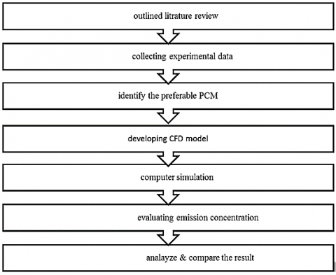
The current research process's methodology is based on the goals set, experimental data from the literature, and computational fluid dynamics modeling. Figure 1 shows the methodology utilized in this work's logical order of activities.
Figure 1. Approach of methodology (Flow chart)
2.1 Mathematical model
2.1.1 Engine wall heat transfer
This equation uses the following constants: k is the molecular conductivity; κ is the von Karman constant (0.4187); B is the function defined by the value of u+ when y+ equals 1; Prm and Prt are the molecular and turbulent prandtl numbers; Tf and Tw are the fluid and wall temperatures; and uτ is the shear speed (derived from the wall's momentum law) [32]. (Eq. (1)) gives the shear speed as:
$u_\tau=c_\mu^{1 / 4} k^{1 / 2}$ (1)
For the O’Rourke and Amsden model, the wall heat transfer is given in Eq. (2):
$k \frac{\partial T}{\partial x_i}=\frac{\mu_m C_p F\left(T_f-T w\right)}{\operatorname{Pr}_m y} n_i$, where, $F$= $\begin{cases}1.0 & y^{+}<11.05 \\ \frac{\left(\frac{y^{+} P r_m}{P_t}\right)}{\frac{1}{x} \ln \left(y^{+}\right)+B+11.05\left(\frac{P_m}{P_{r t}}-1\right)} & y^{+}>11.05\end{cases}$ and $y^{+}=\frac{\rho \mu_\tau y}{u_m}$ (2)
2.2 Overview of system physical model
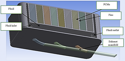
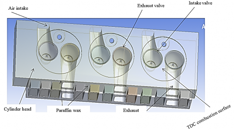
The issue is a finned heat sink geometry to boost phase change materials' capability for heat charging and discharging. By setting periodic boundary conditions to limit the grid size, the domain is made simpler. The study is being done in a way that allows the paraffin wax to compute the performance of phase-change materials. As illustrated in Figure 2, the shape of the heat sink for this investigation places the phase transition materials close to the exhaust port. Figure 3 depicts the physical model of a cylinder head with three cylinders.
Figure 2. Overview of the system modeling
Figure 3. Three cylinders physical model (cylinder head)
The paraffin wax converts from a solid to a liquid state to absorb heat from the combustion chamber. Since the wax's temperature is essentially constant during the phase change process, they may control the combustion temperature using the thermodynamic equilibrium concept until the phase transition is complete. To extract the stored heat from paraffin wax, the fluid may be circulated if the source temperature is excessively high and makes the wax unstable.
2.3 Phase change materials simulation (model) of heat transfer
The temperature affects the density and dynamic viscosity of liquid-phase materials. In Eq. (3), the density of phase-change materials is given in kg/m3 [33].
$\rho=\frac{\rho_{\mathrm{ref}}}{\beta_{\mathrm{t}}\left(t-t_{\mathrm{m}}\right)+1}$ (3)
where, βt is the expansion factor and ρref is the reference density of phase change materials at melting temperature tm. You can choose the value of βt=0.001 K-1. Eq. (4) can be used to compute the dynamic viscosity μ of liquid phase change materials, expressed in kg/ms.
$\mu=\exp \left(-4.25+\frac{1790}{t}\right)$ (4)
where t, is the phase change material's temperature in K. Eq. (5) expresses the energy equation in terms of the sensible enthalpy.
$\begin{gathered}h=\int_{t_{\mathrm{ref}}}^t c_{\mathrm{p}} \mathrm{d} t \\ \frac{\partial \rho h}{\partial x}+\operatorname{div}(\rho \bar{u} h)=\operatorname{div}\left(\frac{\lambda}{c_{\mathrm{p}}} \operatorname{grad} h\right)+Q_{\mathrm{h}}\end{gathered}$ (5)
where, h is the sensible enthalpy, in J/kg; u $1 / 4$ $\partial \ \rho$ u; v; w is the velocity, in m/s; λ is the thermal conductivity, in W/mK; cp is the specific heat at constant pressure, in J/kgK; and Qh is the latent heat source term.
2.3.1 Boundary conditions
Before the thermal load is added to the analysis of the system fluency model and the temperature and mass fraction distribution of phase change materials are calculated, the boundary conditions must be set.
The boundary condition of cylinder head, Eq. (6).
$k x \frac{\delta T}{\delta x} n x+k y \frac{\delta T}{\delta y} n y+k z \frac{\delta T}{\delta z} n z=\alpha(T a-T)$ (6)
where,
$\alpha$=convection coefficient.
K=coefficient of heat conduction
T$\alpha$=temperature of liquid
T=part surface temperature
nx, ny, nz=the direction cosine of the normal to boundary
The limits were defined using numerous changes and calculations using traditional formulae and numbers [34, 35], as shown in Table 1.
Table 1. The values of T and $\alpha$ (Experimental)
|
Location |
$\alpha$-W/(m2.K) |
T(k) |
|
Cylinder head side and upper surface |
23 |
293 |
|
Air intake channel surface |
350 |
335 |
|
Exhaust gas channel surface |
650 |
973 |
|
Combustion chamber surface |
1000 |
1200 |
|
Coolant channel surface |
3000 |
353 |
|
Cylinder head with the contact surface of the inlet valve seat |
150 |
665 |
|
Cylinder head with the contact surface of the exhaust valve seat |
200 |
803 |
|
Bottom surface of Cylinder head |
100 |
503 |
2.3.2 Boundary conditions of the paraffin wax
The latent heat of fusion for paraffin wax is 200 kJ/kg, and the chosen paraffin wax boundary conditions were derived from Tables 2-3 [35, 36].
Table 2. Properties of organic phase change materials
|
Compound |
Density (kg/m3) |
Thermal Conductivity (W/mK) |
Melting Temperature (℃) |
Heat of Fusion (KJ/kg) |
|
Paraffin C14 |
n.a. |
n.a. |
4.5 [1] |
165 [1] |
|
Paraffin C16-C18 |
n.a |
n.a. |
20–22 [29] |
152 [29] |
|
Dimethyl-sulfoxide (DMS) |
1009 (solid and liquid) [28] |
n.a. |
16.5 [28] |
85.7 [28] |
|
Paraffin C15-C16 |
n.a. |
n.a. |
8 [1] |
153 [1] |
|
Paraffin C13-C24 |
0.760 (liquid, 70℃) [1] 0.900 (solid, 20℃) [11] |
0.21 (solid) [1] |
22–24 [1] |
189 [1] |
|
Paraffin C18 |
0.774 (liquid, 70℃) [1] 0.814 (solid, 20℃) [1] |
0.148 (liquid, 40℃) [30] 0.15 (solid) [1] 0.358 (solid, 25℃) [30] |
28 [1] 27.5 [30] |
244 [1] 243.5 [30] |
|
Polyglycol E400 |
1125 (liquid, 25℃) [4,11] 1228 (Solid, 3℃) [4, 11] |
0.187 (Liquid, 38.6℃) [4, 11] 0.185 (Liquid, 69.0℃) [11] |
8 [4, 11] |
99.6 [4,11] |
|
Paraffin C20-C33 |
0.769 (liquid,70℃) [1] 0.912 (solid,20℃) [1] |
0.21 (solid) [1] |
48–50 [1] |
189 [1] |
|
Polyglycol E600 |
1126 (liquid, 25℃) [4, 11] 1232 (Solid, 4℃) [4, 11] |
0.189 (Liquid, 38.6℃) [4, 11] 0.187 (Liquid, 69.0℃) [11] |
22 [4, 11] |
127.2 [4, 11] |
|
1-Dodecanol |
n.a. |
n.a. |
26 [9] |
200 [9] |
|
Paraffin C22-C45 |
0.795 (liquid, 70℃] [1] 0.920 (solid,20℃] [1] |
0.21 (solid) [1] |
58–60 [1] |
189 [1] |
|
1-Tetradecanol |
|
|
38 [9] |
205 [9] |
|
Paraffin wax |
790 (liquid, 65℃) [4, 11] 916 (solid, 24℃) [4, 11] |
0.167 (liquid, 63.5℃) [4, 11] 0.346 (solid, 33.6℃) [4, 11] |
64 [4, 11] |
173.6 [4, 11] 266 [6] |
|
Paraffin C16-C28 |
0.765 (liquid, 70℃] [1] 0.910 (solid,20℃] [1] |
0.21 (solid) [1] |
42–44 [1] |
189 [1] |
Table 3. Paraffin wax (selected) thermal properties
|
Temp. (℃) |
Density (kg/m3) |
Specific Heat (J/kg-K) |
Thermal Conductivity (W/m-K) |
Viscosity (kg/m-s) |
|
45 |
760 |
2380 |
0.111 |
0.00049 |
|
40 |
790 |
2280 |
0.118 |
0.00052 |
|
35 |
820 |
2240 |
0.122 |
0.00055 |
|
30 |
870 |
2200 |
0.139 |
0.00060 |
|
25 |
900 |
2140 |
0.150 |
0.00069 |
The developed three-dimensional model enables the simplification of certain of the structures, such as ribs, pin holes, and bolt holes. Temperature and the distribution of the stress field have very little impact on these structures. The dimensions and shapes of non-simplified structures determine how the data should be correctly analyzed.
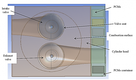
Applying the boundary conditions to one combustion surface will simplify the model even further. In order to prepare the model for the investigation of the transient temperature distribution and wax mass fraction, do the following. Figure 4 depicts a physical model of a single cylinder for the study of phase change materials.
Figure 4. Paraffin wax near to exhaust port of cylinder head near to combustion chamber
Note: One paraffin wax_volume=20880 mm3; Paraffin wax_total volume=204400 mm3
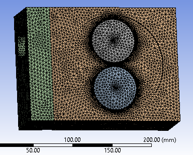
Figure 5. Mesh generation
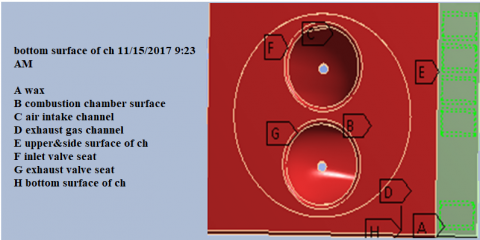
Figure 6. Set up and conditions of boundary
2.4 Generation of mesh and numerical modelling preparation
The mesh report is presented in Table 4, and Figure 5 depicts the mesh production. Figure 6 shows the setup and boundary conditions.
Table 4. Mesh production report
|
Domain |
Elements |
Nodes |
|
Head_cylinder |
354789 |
68341 |
|
Valve_exhaust |
23929 |
5273 |
|
Valve_intake |
23846 |
5293 |
|
Contaniner_pcm |
33346 |
8152 |
|
Wax |
1800 |
2800 |
|
Domains_All |
437710 |
89859 |
3.1 Composite system heat flux and transient temperature
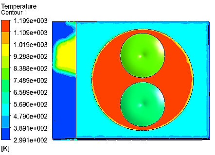
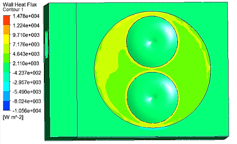
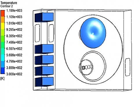
Figure 7 shows that the temperature on the surface of the combustion chamber is at its highest, while the temperature on the side and upper surface of the cylinder head is at its lowest. Furthermore, there will be an increase in the quantity of heat flow (in the form of wax) toward the exhaust port. More heat is absorbed by this substance as the wax melts, and it does so until the phase change is almost complete at a constant temperature. Other authors claim that the performance of the thermal energy storage system is more significantly affected by the temperature difference between the PCM's melting point, and the air utilized as the heat transfer fluid. When the mean temperature of the PCM falls by 10 K below the temperature of the intake air, the maximum amount of thermal energy is recovered from the store. This resulted in a correlation between the melting front distribution and the solid proportion as well as the charging and discharging timing of thermal energy storage. The construction and improvement of heating and cooling systems are made feasible by this combination [33]. Other authors have also demonstrated the benefits of a system that combines latent heat storage and sensible from the exhaust of diesel engine for waste heat recovery [16]. The scientists came to the conclusion that for the best outcomes, materials with multiple-phase transition in a cascaded storage medium would be ideal for enhancing heat recovery because employing paraffin as a single-phase change material did not yield superior results, despite the benefits [18].
Figure 7. Temperature and wall heat flux contour of composite system
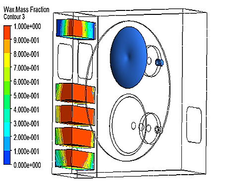
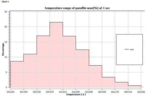
3.2 Paraffin wax mass fraction and distribution of transient temperature
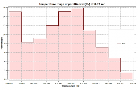
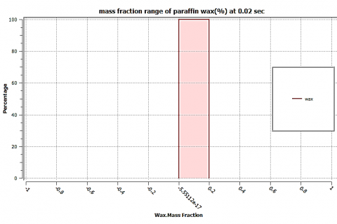
The highest temperature at which a percentage of paraffin wax can reach 332 K (59℃) in a second is depicted in Figure 8. This indicates that a percentage of paraffin wax completely changes from a solid to a liquid condition during that time. Figure 9 shows that 0.6% of the paraffin wax is at a temperature of 329–332 K. Nonetheless, more than 19% of the paraffin wax is always above melting point since it is believed to melt at 313 K. On the other hand, Figure 10's paraffin wax is unable to melt in 0.02 seconds.
According to studies by other authors [36, 37], when hydrogen dual-fuel operation—which uses fuel that is close to pilot fuel—was utilized in place of diesel fuel compression ignition engine operation, nitrogen oxide emissions were raised by about 38%. This spike was caused by the higher combustion temperature and pressure that came with running on dual fuel.
According to the authors, higher combustion reaction rates were observed. When the engine's speed was decreased, a 22% decrease in nitrogen oxide emissions was observed. This reduction was brought on by charge cooling. However, as engine speed was raised, nitrogen oxide levels rose across the load range. According to reports, PCM can help us better comprehend the thermal energy of exhaust gases. Melting it and storing the resulting latent heat accomplishes this.
Figure 8. Paraffin wax mass fraction and temperature contour
The possibility of increasing the effectiveness of emission reduction through heat transfer between PCM and the catalytic substrate has been covered by several authors. By utilizing thermal energy storage (TES), a diesel engine's after-treatment system may be able to significantly reduce emission discharge. Experimental and computational investigations have been published on the use of phase transition materials as exhaust gas energy storage [38, 39]. It has been noted that using PCM as a heat storage system offers several beneficial properties, including chemical stability, consistent heat delivery, and minimal temperature loss [40]. Because of its superior thermal properties, paraffin wax was one of the most sought-after kinds of PCM. Although its low heat conductivity has been mentioned as a disadvantage in a number of papers [41], Nonetheless, some writers had suggested using a number of PCMs inside a unit with different operating temperatures. The authors asserted that employing many PCMs would enhance the system's thermal performance as opposed to utilizing just one [41].
In addendum, heat transmission (latent heat phase) is enhanced when a PCM storage system is combined with a material that has a high thermal conductivity. Direct contact heat exchangers are made possible by capillary forces and surface tension that work with the PCM and ceramic structure to stabilize and hold the molten PCM inside the microporosity of the structure as reported by other authors [42]. Admixtures of carbon nanomaterials can improve the thermal conductivity of PCM, although the effect is mostly dependent on how well the nanomaterials disperse throughout the material. The homogeneous distribution of the nanomaterial throughout the material during this process produces uniform composite phase change material (CPCM). The additives must be chemically stable and have a high thermal conductivity in order to ensure that the thermal conductivity is successfully boosted while also preventing chemical reactions [42].
Reduced heat conductivity in PCM significantly affects the device's efficiency. When conductivity values are lowered, rather considerable temperature drops are seen throughout the energy withdrawal or retrieval process. As a result, the rate of PCM melting and solidification has not increased as expected, and the large-scale LHTS unit deployment has not worked out. Common results of this scenario include incomplete melting or solidification and a large temperature differential inside the PCM, both of which can lead to the material's eventual failure and system overheating [42].
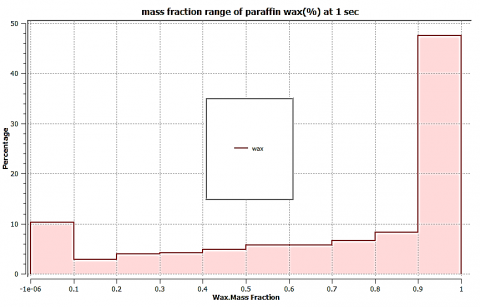
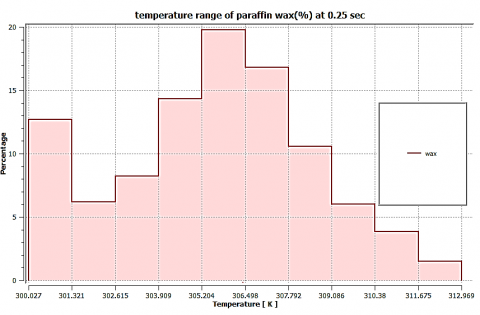
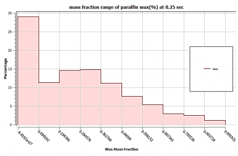
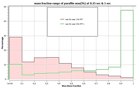
Figure 11 shows that much of the paraffin wax has completely changed phases. (The range of the mass fraction is 0.9 to 1). Wax mass fractions at 0.02 seconds are practically non-existent, as Figure 12 illustrates. Furthermore, the paraffin wax in Figure 13, which begins to change phases at 0.25 seconds (2.5%), follows suit. The effect is that more heat from the combustion chamber is now absorbed by the wax. Figure 14 shows that the majority of paraffin wax mass fractions are practically less than 0.09 percent. Paraffin wax temperature and mass fraction at 1 and 0.25 seconds are compared. As shown in Figure 13, the majority of paraffin wax mass fractions are almost less than 0.09. Paraffin wax temperature and mass fraction at 1 and 0.25 seconds are compared.
The charts 1 and 3 in Figures 8 and 10 show that the maximum temperature of 1% paraffin wax for a second is 330 K, that 43% of the wax is solid, and that 57% of the mass fraction is between 0.1 and 0.9 at this point. As shown in charts 7 and 8 in Figure 13, paraffin wax goes through a phase transition that begins at 0.25 seconds and lasts generally at a constant temperature until 100% of the wax mass fraction transforms into 1. As long as the mass fraction of the total wax stayed at 1, the temperature of the combustion chamber would not increase above room temperature throughout this phase change. This would be possible thanks to the principle of thermal equilibrium.
Figure 9. Paraffin wax range of temperature at 1.00 second
Figure 11. Paraffin wax mass fraction range at 1 second
Figure 12. Mass fraction range of paraffin wax at 0.02 second
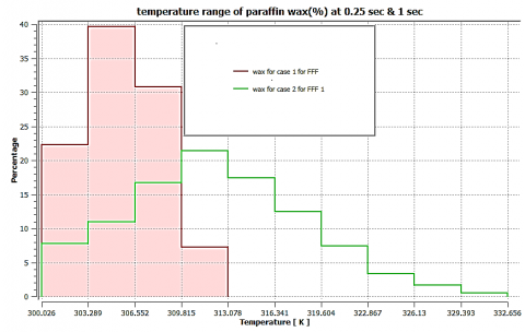
The highest temperature of 1% paraffin wax for one second is 330 K, as shown in Figures 9 and 11. Currently, 43% of the wax is solid and 57% of the mass fraction is between 0.1 and 0.9. As demonstrated in Figures 15 and 16, the research indicates that the paraffin wax undergoes a phase transition that starts at 0.25 seconds and lasts for approximately at a constant temperature until 100% of the wax mass fraction changes to 1. Thus, during this phase change, the combustion chamber's temperature would not rise over room temperature as long as the mass fraction of the entire wax remained at 1. This would be possible thanks to the principle of thermal equilibrium.
Figure 15. Case 1 wax mass fraction at 0.25 second, Case 2 wax mass fraction at 1 second
Figure 16. Case 1 wax temperature range at 0.25 second, Case 2 wax temperature range at 1 second
[1] World Energy Outlook. (2017). International Energy Agency. https://www.iea.org/reports/world-energy-outlook-2017.
[2] Kim, H., Junghans, L. (2022). Integrative economic framework incorporating the Emission Trading Scheme (ETS) for U.S. Residential energy systems. Energy Conversion Managemen: X, 14: 100197. https://doi.org/10.1016/j.ecmx.2022.100197
[3] Aridi, R., Faraj, J., Ali, S., Lemenand, T., Khaled, M. (2021). Thermoelectric power generators: State-of-the-art, heat recovery method, and challenges. Electricity, 2: 359-386. https://doi.org/10.3390/electricity2030022
[4] Esbati, S., Amooie, M.A., Sadeghzadeh, M., Ahmadi, M.H., Pourfayaz, F., Ming, T.Z. (2019). Investigating the effect of using PCM in building materials for energy saving: Case study of Sharif Energy Research Institute. Energy Science & Engineering, 8: 959-972. https://doi.org/10.1002/ese3.328
[5] Aridi, R., Faraj, J., Ali, S., El-Rab, M.G., Lemenand, T., Khaled, M. (2021). Energy recovery in air conditioning systems: Comprehensive review, classifications, critical analysis, and potential recommendations. Energies, 14(18): 5869. https://doi.org/10.3390/en14185869
[6] Al-Yasiri, Q., Szabó, M. (2021). Selection of phase change material suitable for building heating applications based on qualitative decision matrix. Energy Conversion and Management: X, 12: 100150. https://doi.org/10.1016/j.ecmx.2021.100150
[7] Yehya, A., Naji, H. (2015). Thermal lattice Boltzmann simulation of entropy generation within a square enclosure for sensible and latent heat transfers. Applied Sciences, 5(4): 1904-1921. https://doi.org/10.3390/app5041904
[8] Pavlov, G.K., Olesen, B.W. (2011). Building thermal energy storage – Concepts and applications. Engineering, Environmental Science. https://backend.orbit.dtu.dk/ws/portalfiles/portal/6383088/BUILDING+THERMAL.pdf.
[9] Darkwa, K., O'Callaghan, P.W. (1997). Green transport technology (GTT): analytical studies of a thermochemical store for minimising energy consumption and air pollution from automobile engines. Journal of Applied Thermal Engineering, 17: 603-614.
[10] Porisini, F.S. (1988). Salt hydrates used for latent heat storage: corrosion of metals and reliability of thermal performance, Solar Energy, 41(2): 193-197. https://doi.org/10.1016/0038-092X(88)90136-3
[11] Khadrawi, A.F., Balabel, A., Al-Osaimy, S. (2014). A new cooling technique using phase change material in a car ceiling and wall buildings. International Journal of Heat and Technology, 32(1-2): 185-190. https://doi.org/10.18280/ijht.320126
[12] Raja, S.P., Rajavel, R., Navaneethakrishnan, D. (2014). Experimental investigation of heat recovery from diesel engine exhaust using compact heat exchanger and thermal storage using phase change material. International Journal of Innovative Research in Science, Engineering and Technology, 3(3): 2663-3670.
[13] Schatz, O. (1992). Cold start improvement by use of latent heat stores. SAE Technical Paper, 921605. https://doi.org/10.4271/921605
[14] Vasiliev, L.L., Burak, V.S., Kulakov, A.G., Mishkinis, D.A., Bohan, P.V. (2000). Latent heat storage modules for preheating internal combustion engine. Applied Thermal Engineering, 20(10): 913-923. https://doi.org/10.1016/S1359-4311(99)00061-7
[15] Korin, E., Reshef, R., Tshernichovsky, D., Sher, E. (1999). Reducing cold start emission from internal combustion engines by means of a catalytic converter embedded in a phase change material. In Proceedings of the Institution of Mechanical Engineers, Part D: Journal of Automobile Engineering, 213(6): 575-583. https://doi.org/10.1243/0954407991527116
[16] Subramanian, S.P., Pandiyarajan, V., Velraj, R. (2004). Experimental analysis of a PCM based IC engine exhaust waste heat recovery systems. International Energy Journal, 5(2): 81-92.
[17] Pandiarajan, V., Chinna Pandiyan, M., Malan, E., Velraj, R., Seeniraj, R.V. (2011). Experimental investigation on heat recovery from diesel engine exhaust using finned shell and tube heat exchanger and thermal storage system. Applied Energy, 88(1): 77-87. https://doi.org/10.1016/j.apenergy.2010.07.023
[18] Wu, J.H., Yang, Z.G., Wu, Q.H., Zhu, Y.J. (2012). Transient behaviour and dynamic performance of cascade heat pump water heater with thermal storage system. Applied Energy, 91(1): 187-196. https://doi.org/10.1016/j.apenergy.2011.09.020
[19] Merker, G., Schwarz, C., Stiesch, G., Otto, F. (2006). Simulation derVerbrennung und Schadstoffbildung. Vieweg+Teubner Verlag.
[20] Wei, L.J., Yao, C.D., Wang, Q.G., Pan, W., Han, G.P. (2015). Combustion and emission characteristics of a turbocharged diesel engine using high premixed ratio of methanol and diesel fuel. Fuel, 140: 156-163. https://doi.org/10.1016/j.fuel.2014.09.070
[21] Pitz, W.J., Cernansky, N.P., Dryer, F.L., Egolfopoulos, F.N., Farrell, J.T., Friend, D.G., Pitsch, H. (2007). Development of an experimental database and chemical kinetic models for surrogate gasoline fuels. SAE Technical Papers, 2007(724): 776-790. https://doi.org/10.4271/2007-01-0175
[22] Bayraktar, H. (2008). An experimental study on the performance parameters of an experimental CI engine fueled with diesel-methanol-dodecanol blends. Fuel, 87(2): 158-164. https://doi.org/10.1016/j.fuel.2007.04.021
[23] Lawrence, M.G., Crutzen, P.J. (1999). Influence of NOx emissions from ships on tropospheric photochemistry and climate. Nature, 402(6758): 167-170. https://doi.org/10.1038/46013
[24] Raub, J.A., Mathieu-Nolf, M., Hampson, N.B., Thom, S. R. (2000). Carbon monoxide poisoning: A public health perspective. Toxicology, 145(1): 1-14. https://doi.org/10.1016/S0300-483X(99)00217-6
[25] Anderson, J.O., Thundiyil, J.G., Stolbach, A. (2012). Clearing the air: A review of the effects of particulate matter air pollution on human health. Journal of Medical Toxicology, 8(2): 166-175. https://doi.org/10.1007/s13181-011-0203-1
[26] Weaver, C.S. (1989). Natural gas vehicles-A review of the state of the art. SAE Technical Papers, 98: 1190-1210. https://doi.org/10.4271/892133
[27] Liu, S.H., Zhou, L.B., Wang, Z.Y., Ren, J. (2003). Combustion characteristics of compressed natural gas/diesel dual-fuel turbocharged compressed ignition engine. In Proceedings of the Institution of Mechanical Engineers, Part D: Journal of Automobile Engineering, 217(9): 833-838. https://doi.org/10.1177/095440700321700909
[28] Cho, H.M., He, B.Q. (2007). Spark ignition natural gas engines-A review. Energy Conversion and Management, 48(2): 608-618. https://doi.org/10.1016/j.enconman.2006.05.023
[29] Korakianitis, T., Namasivayam, A.M., Crookes, R.J. (2011). Natural-gas fueled spark-ignition (SI) and compression-ignition (CI) engine performance and emissions. Progress in Energy and Combustion Science, 37(1): 89-112. https://doi.org/10.1016/j.pecs.2010.04.002
[30] Hagos, D.A., Ahlgren, E.O. (2018). Well-to-wheel assessment of natural gas vehicles and their fuel supply infrastructures – Perspectives on gas in transport in Denmark. Transportation Research Part D: Transport and Environment, 65: 14-35. https://doi.org/10.1016/j.trd.2018.07.018
[31] Dolter, B., Seatle, M., McPherson, M. (2023). When the sun sets on net metering: How the cancellation of net metering impacted the potential adoption of residential rooftop solar photovoltaics in Regina, Saskatchewan. Challenges in Sustainability, 10(1): 47-76. https://doi.org/10.12924/cis2023.10010047
[32] Dayal, A., Shrivastava, M., Upadhyaya, R., Brar, L.S. (2019). Numerical study using detailed chemistry combustion comparing effects of wall heat transfer models for compression ignition diesel engine. SN Applied Sciences, 1: 1005. https://doi.org/10.1007/s42452-019-1033-z
[33] El-Sawi, A., Haghighat, F., Akbari, H. (2013). Centralized latent heat thermal energy storage system: Model development and validation. Energy and Buildings, 65: 260-271. https://doi.org/10.1016/j.enbuild.2013.05.027
[34] Wang, X.W., Lu, E.R., Lin, W.X., Liu, T., Shi, Z.S., Tang, R.S., Wang, C.Z. (2000). Heat storage performance of the binary systems neopentyl glycol/pentaerythritol and neopentyl glycol/trihydroxy menthyl-aminomethane as solid phase change materials. Energy Conservation and Management: 129-134. https://doi.org/10.1016/S0196-8904(99)00097-7
[35] Farid, M.M., Khudhair, A.M., Razack, S.A.K., Al-Hakkaj, S. (2004). A review on phase change energy storage: materials and applications. Energy Conversion and Management, 45(9-10): 1597-1615. https://doi.org/10.1016/j.enconman.2003.09.015
[36] Namasivayam, A.M., Korakianitis, T., Crookes, R.J., Bob-Manuel, K.D.H., Olsen, J. (2010). Biodiesel, emulsified biodiesel and dimethyl ether as pilot fuels for natural gas fuelled engines. Applied Energy, 87(3): 769-778.
[37] Korakianitis, T., Namasivayam, A.M., Crookes, R.J. (2010). Hydrogen dual-fuelling of compression ignition engines with emulsified biodiesel as pilot fuel. International Journal of Hydrogen Energy, 35(24): 13329-13344. https://doi.org/10.1016/j.ijhydene.2010.08.007
[38] Guerraiche, D., Bougriou, C., Guerraiche, K., Valenzuela, L., Driss, Z. (2020). Experimental and numerical study of a solar collector using phase change material as heat storage. Journal of Energy Storage, 27: 101133.
[39] Haghighi, A., Aziz, B., Azizi, M., Javanshir, Z., Ghasemzade, H. (2020). Optimization of the thermal performance of PCM nanocomposites. Journal of Energy Management and Technology, 4(2): 14-19. https://doi.org/10.22109/jemt.2019.152458.1134
[40] Hosseini, M.J., Ranjbar, A.A., Sedighi, K., Rahimi, M. (2012). A combined experimental and computational study on the melting behavior of a medium temperature phase change storage material inside shell and tube heat exchanger. International Communications in Heat and Mass Transfer, 39(9): 1416-1424. https://doi.org/10.1016/j.icheatmasstransfer.2012.07.028
[41] Jesumathy, S., Udayakumar, M., Suresh, S. (2012). Experimental study of enhanced heat transfer by addition of CuO nanoparticle. Heat and Mass Transfer, 48(6): 965-978. https://doi.org/10.1007/s00231-011-0945-y
[42] Rathod, M.K. (2022). Introductory Chapter: Phase Change Material as Energy Storage Substance. Phase Change Materials - Technology and Applications. IntechOpen. https://doi.org/10.5772/intechopen.108863