Ali Raad Hassan![]() | Malik N. Hawas
| Malik N. Hawas![]() | Atheer Raheem Abdullah
| Atheer Raheem Abdullah![]() | Hasan Shakir Majdi
| Hasan Shakir Majdi![]() | Laith Jaafer Habeeb*
| Laith Jaafer Habeeb*![]()
© 2023 IIETA. This article is published by IIETA and is licensed under the CC BY 4.0 license (http://creativecommons.org/licenses/by/4.0/).
OPEN ACCESS
Helical gears, due to their increased contact region during the engagement cycle and consequent reduction in noise, have become ubiquitous in mechanical engineering applications and thus form the focal point of this study. This research paper meticulously examines the position of the helix angle and comprehensively evaluates its influence on the reaction force and its evolution on the gear shaft. The results reveal an optimal helix angle of 30 degrees, which minimizes the stress impact on the shaft. In contrast to the typical 40-degree angle, a reduced helix angle of approximately 5 degrees results in the largest displacement along the x-axis for gear 3 at a rotational speed of 590 rad/s, reaching up to 0.15 micrometers. Furthermore, the lowest percentage error can be observed at the 5-degree angle, with a maximum value of 0.8 degrees. A maximum reaction force of 1080 N is observed at a helix angle of 5 degrees, which increases further with the length of the helix. These results provide compelling evidence in favor of the 5-degree angle as opposed to significantly larger angles. The force exerted on the shaft, viewed from two distinct axes, and its temporal evolution are also meticulously examined, providing valuable insights into the dynamic stress of high-speed helical gears.
FEM, helical gear, pressure angle, helix angle, stress analysis, simulation
Innovative pure rolling gear drives hinge on the dynamic design of the cross-sectional profile. When compared to traditional involute helical gear drives, these gears exhibit enhanced contact and bending stresses. However, the potential of pure rolling cylindrical helical gears for application in plastic gear systems is noteworthy. The unique characteristic of pure rolling mesh contributes to a lower heat generation and enhances the rigidity of the gears [1].
Gears, specifically helical gears, are commonly utilized to transmit mechanical power, with the distinct ability to do so more smoothly than other gear types. The forces exerted upon gear teeth significantly influence operational limits, subjecting them to stresses that can lead to failure. One such force, the root bending stress, has been identified as a key contributor to tooth failure in helical gears.
This paper further investigates the impact of tooth bending stress on single and herringbone helical gear systems. A comparative analysis is conducted between the results obtained from a finite element analysis and those from a theoretical investigation, shedding light on the effects of root bending stress on these gear systems [2]. This comparative study elucidates the intricacies of gear design, ultimately contributing to our understanding of the dynamic stress in high-speed helical gears.
The demand for gears with high load-bearing capacity, efficiency, cost-effectiveness, low noise, and compact size continues to grow. This study confines the volume of a helical gear pair through the use of Real Coded Genetic Algorithm (RCGA), introducing profile shift coefficients as design variables alongside module, the number of teeth, and face width. The optimization process incorporates the constraints of tooth contact and bending stress. Upon comparing volumes with and without profile shift, it has been found that the volume with profile shift is smaller. The research paper conducted an analytical study on two gear teeth and utilized a complete gear assembly [3].
For low weight, high efficiency, and minimal noise, the comprehensive computation of a helical gear pair was streamlined. Optimal responses for five combinations of the three objectives were analyzed. The design aims to enhance the mass and efficiency of the gear. The gear noise design objective was selected as the peak-to-peak static transmission error (PPSTE), a primary source of gear vibration. The research paper analytically examined the left angle of one gear without addressing the topic of transmission error [4].
A method for calculating the failure probability of cylindrical gears with arc-shaped (circular) teeth along their length, due to bending endurance, was developed. The solution to the problem is obtained using the tool of nonparametric statistics, enabling failure probability calculation regardless of the complexity of the stresses occurring at the teeth root during gear operation. The research paper primarily discussed types of gears and retainers [5].
Asymmetric helical gears have been under scrutiny for over two decades due to their inherent ability to handle greater bending stresses. In this type of gear, only one side of each gear tooth in a geared element is usually loaded (driving/driven side), while the other remains largely unloaded (coast side). Owing to the deviation of the tooth, a nonlinear model is utilized. The basic calculation is initially generated in 2D and later converted to a 3D shape using Boolean operations. The research paper discussed the stresses generated as a result of interlock but did not conduct an analysis of the issue of Transmission Error [6].
Gear parameters such as pressure angle, helix angle, etc., impact the load-bearing capacity of gear teeth. Failure at the critical section due to bending stress is an inevitable peculiarity, but the degree of these failures can be mitigated by appropriate gear design. Results show that the experimental method provides bending stress values closer to the actual value, and bending stress varies with Pressure angle and Helix angle. The research paper discussed gear angles and pressure angles under the influence of non-fixed variables, which is the focus of the presented work, but did not take into account transmission error [7]. Ductile stress and compressive stress could be reduced by 10% with an increase in the helix angle. The coefficient of friction significantly impacts the tensile stress of gear pairs. Owing to its influence, the peak advantage of time-varying tooth-root stress transitions from High Point Surface Tooth Contact (HPSTC) to Low Point Surface Tooth Contact (LPSTC). In double tooth contact conditions, the increase in parallel misalignment may be mitigated by up to 18% during the approach phase. The research paper studied the addressed mechanical errors analytically [8].
This study evaluated the impact of gear tooth addendum and dedendum on the improved results for full-scale gear design. Initially, full-scale design parameters such as mass, gear mesh efficiency, and transmission errors were employed to optimize the gear, resulting in comparable constraints for both the pinion and wheel. The results indicate that the average score for the optimization, considering only the primary design variables, was 2.7085. When including the Addendum and Dedendum, the average scores were 2.7829 and 2.8830, respectively. The research paper conducted an analytical study on two gear teeth and incorporated a complete gear assembly [9].
Enhanced modification in tooth profile has significant benefits in gear operations. The impact of profile shift and specific sliding on the design optimization of helical gear pair have been considered. Preventing undermining, balancing wear, and bending fatigue strength, and center distance adjustment are some advantages of profile tooth modifications. 3D Computer-Aided Design (CAD) models were developed using the optimized results obtained from RCGA and commercially used software. The research focused on adjusting or achieving optimal shapes for mechanical gears and understanding the intersection points between two gears [10].
Determining the actual bending stresses at the tooth root is a crucial step in the precise design of gears. The photo stress coating method, along with a reflection polariscope, was utilized as an experimental technique. Speed factor method and Spot's equation method were employed to estimate dynamic load and bending stress at the critical section of the tooth. The research conducted a study on the impact of stresses on the motor gear in a time-variant state [11]. Inevitable misalignment and microgeometry are crucial considerations in gear design as they influence the resulting stresses, transmission error, and dynamic response. Analyzing the stress concentration on tooth root and flank areas is vital for predicting potential failure mechanisms. Different tools for modeling gear teeth resulted in much larger loads than the Software. Case 3 demonstrated that compensating for the effects of misalignment in operation could be achieved using microscopic geometric adjustments. Micro gears and the impact of mesh were used to obtain controllable results [12].
The author proposes a method for constructing a high-accuracy three-dimensional (3D) Finite Element Model (FEM) of involute helical gears. The FEM of the helical material is built without the need for CAD software or the creation of a calculation model in advance, using a bottom-up modeling technique. To enhance the mesh quality and precision, a local refinement method for the hexahedral element was developed. Based on the quasistatic loaded tooth contact analysis, the tooth load sharing percentage, static transmission error, mesh stiffness, root bending stress, and contact stress are obtained using the proposed model. The paper discussed the point contact between gears and its effect on the resulting stresses [13].
A paper presents an improved model developed by the Hybrid User-Defined Element Method (HUELM) for dynamic analysis of a double helical gear reduction unit. The model consists of four developed elements to individually simulate the gear pair, bearings, flexible shafts, and the housing. It is more efficient than the Finite Element Method (FEM) and lumped mass method (LMM) and is suitable for large-scale analysis of transmission gear. The research paper examined a complex of gears with the effect of gearing on stresses, as well as the effect of acceleration [14].
Arc face gear transmission is a new type of gear transmission that can address the problem of root bending strength in eccentric straight and helical arc face gear. In this study, the plane equal pitch arc was obtained by deriving a condition of pitch arc, pressure angle, and contact ratio in the meshing process. The impact of the primary design boundaries on bending stress was also studied in depth. The paper investigates the bending stresses of gears [15].
This research addresses the issue of unbalanced loading of helical gears using a mechanism for the unique variation of tooth width. During experimental testing, the redesigned gear's swing vibration response is reduced by a maximum of 26.15 percent. The dynamic load coefficient is also reduced by a maximum of 20.84 percent, and stress is evenly distributed on the tooth surface. The results of the linear forces that significantly affect the gears were obtained, necessitating calculations for the transmission error [16].
The study explores the impact of gear tooth spalling in a helical gear. A scientific model was developed to focus on the effect on the time-varying mesh stiffness, contact stress, and tooth root fillet stress. A Finite Element Method is presented for simulation, to analyze the mesh stiffness and stresses obtained from the mathematical method under different spalling factors. The study generally discusses the effect of the mesh in resolving the results [17]. This research explores the effects of the contact design plan on the mechanical and thermal behavior of plastic-steel helical gear drives. For various designs of the pinion tooth surfaces, key parameters such as maximum contact pressure, frictional power loss, transmission error work, and operating temperature were determined. The findings show that a well-thought-out design can help reduce the peak contact pressure and maximum operating temperature while enhancing the solidity of the transmission. The paper discussed the thermal effects resulting from gear engagement [18].
The review proposes a nonlinear hybrid dynamic model of a helical gearbox. The nonlinear coupling effect of time-varying mesh stiffness (TVMS) and transmission error excitation is considered in the model. The impacts of tip relief and crowned lead on the dynamic characteristics of the helical gear transmission system's TVMS are examined. The theoretical model is validated against an experimental setup of a high-speed rail traction gearbox transmission structure, and strong responses are considered. The paper studied the non-linear motion in gearing and does not address the transmission error [19].
The research aims to limit the stress and optimize the design, focusing on the effect of the Profile Shift Factor x on the stress generated at the base of the spur gear teeth pair. According to the LEWIS theory, the potential effects of bending stress are estimated using ISO standard conditions and verified by Finite Element Method (FEM) using ANSYS software. The paper discussed standard gears and the effect of bending stress on them [20].
The objective is to minimize volume while considering tooth root bending strength, contact stress, face width, and addendum modification coefficients as constraints. Profile changes in the gear significantly influence its structure, area, stress factors, transverse and face load factors. Simulation results with and without profile shift, implementation of various algorithms are explored and validated with literature. The research paper discussed the effect of the shaft on the movement of the gears [21].
Case-carburizing of helical gears with large helix angles may cause the formation of excessively thick hardened layers at the tooth width end on the acute point side (ACUTE-END), which could adversely impact bending fatigue strength. It was found that ISO 6336-3:2006 overestimated the rate of increase of the permissible circumferential loads for similar angles beyond about 30° based on the obtained bending fatigue limits. The paper studied the bending stresses of gears [22].
The reason for the failure of a secondary driving helical gear in electric vehicle transmissions was investigated. The primary cause was the material's low Ti concentration, which led to hardening depth and hardness in the root area, as well as several large carbides on the Martensite lattice due to improper heat treatment. The fatigue failure could have been caused by high contact pressure in the root position and impact load at the initial stage of gear meshing during operation. The study included the concept of electric cars and the method of interlocking gears [23].
Simulation models for coast flank and drive flank injections were developed using skewed helical gear injection oil. The effects of different stuffing rates and spray speeds on the oil volume fraction and strain are examined. The drive flank injection method obtains superior oil when the spray speed is more than 2.7 times the pitch line speed. The paper discussed the thermal effects resulting from gear engagement [24].
The aim of this research is to investigate the impact of tooth profile modifications on helical gear transmission errors. The contact pressure was examined for different roll positions to determine the most critical roll point in terms of root flank pressure. From the root to the tip, the optimal profile is proposed. With a two-layer FEM, the PPTE (peak-to-peak transmission error) is assessed at the roll points under different loading conditions. The study focused analytically on reducing the transmission error, but in a constant state with time and not changing [25].
The aim of this work is to investigate the important parameters of helical gear and to achieve this aim, the following objectives are accomplished:
• Study helix angle effect on stress;
• Study helix angle effect on gear orbits;
• Study helix angle effect on gear X-displacement;
• Study helix angle effect on gear Z-rotation;
• Study helix angle effect on gear Transmission error;
• Study helix angle effect on reaction force.
3.1 Materials and methods
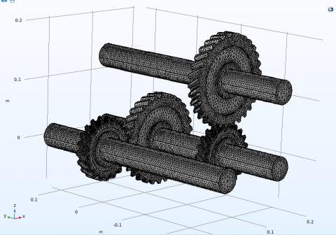
The model was designed with the Solidworks program, which is a precise engineering design program used in engineering simulation programs, where the models were designed according to the rules of ISO and gears were interlocked and using a set of helix angle variable to see which one is better in terms of carrying it during use as shown in Figure 1.
Figure 1. Geometry of helical gear
3.2 Mesh
After completing the model design completely, it is necessary to check the accuracy of the mesh. This is done by reducing the size of the element and displaying the results until a good convergence is reached in the variables of the results, which is called mesh reliability as shown in Table 1.
Table 1. Mesh independency
|
Case |
Element |
Bearing Forces on x-axis (N) |
|
1 |
110575 |
1499 |
|
2 |
183543 |
1469 |
|
3 |
233876 |
1461 |
|
4 |
275828 |
1460 |
Mesh independency was done for bearing forces on x-axis, and the study proved that the error value reached 0.001%, and this is what makes the mesh integrated for this case. Where the element count reached 275828 at bearing forces on x-axis 1460 N, which is sufficient to simulate the situation and reach results close to reality as shown in Figure 2.
Figure 2. Mesh geometry
3.3 Boundary conditions
The study was done in terms of moving the main shaft with a number of revolutions of 1500 revolutions, a time of 0.06 s, and a torque of 100 N. As for the study of vibrations, it took variable speeds from 0 to 9000 with a change of 500 RPM. In many cases, angles helix (5, 10, 20, 30, and 40) were taken, see Table 2.
Table 2. Dimensional parameters
|
Name |
Expression |
Value |
Description |
|
n1 |
20 |
20 |
Number of teeth,gear-1
|
|
d1 |
100 [mm] |
0.1 m |
Pitch diameter, gear-1 |
|
n2 |
30 |
30 |
Number of teeth, gear-2 |
|
d2 |
150 [mm] |
0.15 m |
Pitch diameter, gear-2 |
|
alpha |
25[deg] |
0.43633 rad |
Pressure angle |
|
beta |
40[deg] |
0.69813 rad |
Helix angle |
|
gr |
n2/n1 |
1.5 |
Gear ratio |
|
kg |
2e[N/m] |
2E6 N/m |
Gear mesh stiffness |
|
kb |
1e7[N/m] |
1E7 N/m |
Bearing stiffness |
|
omega |
1500[rpm] |
251/s |
Angular speed of driver shaft |
|
Text |
1e2[ N*m] |
100 N⋅m |
Resisting torque on driven shaft |
|
t_end |
1.5/omega |
0.06 s |
Total simulation time |
3.4 Governing equations
The general equilibrium equations for a static analysis of a linear structure are:
$[K]\{u\}=\{F\}$ (1)
$[K]\{u\}=\left\{F^a\right\}+\left\{F^r\right\}$ (2)
where, $[\mathrm{K}]=\sum_{m=1}^N\left[K_e\right]=$ matrix of total stiffness (N/m); {u}=vector of nodal displacement (m); N=elements number; [Ke]=matrix of element stiffness (in the Element Library described) (The element stress stiffness matrix might be present (Stress Stiffening describes)) (N/m); {Fr}=load vector reaction (N); {Fa}=The definition of the overall load vector is as follows(N):
$\left\{F^a\right\}=\left\{F^{n d}\right\}+\left\{F^{a c}\right\}+\sum_{m=1}^N\left(\left\{F_e^{t h}\right\}+\left\{F_e^{p r}\right\}\right)$ (3)
where, {Fnd}=nodal load vector that was used (N); {Fac}=-[M]{ac}=load vector acceleration (m2/s); $[M]=\sum_{m=1}^N\left[M_e\right]$=overall mass matrix (kg); [Me]=matrix of element mass (Derivation of Structural Matrices describes) (kg); {ac}=overall acceleration vector (established in the Acceleration Effect) (m2/s); $\left\{F_e^{t h}\right\}$=thermal load vector of an element (Derivation of Structural Matrices describes) (N); $\left\{F_e^{p r}\right\}$=load vector element pressure (Derivation of Structural Matrices describes) (N) [10].
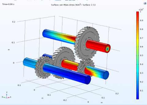
4.1 Helix angle effect on stress
The effect of the helix angle has negative aspects on some variables or mechanical phenomena and positive aspects on others. From Figure 3, it can be seen that the value of the stress has a large distribution on the shaft in corners 5, 10, and 40, but in corners 20 and 30, its distribution is less, and this stress is scattered in the last shaft, where the stress on it is very little compared to the rest.
Where it is noted that the best condition reached in the angles of helical gears is 30, where the effect of stresses on the shaft is relatively small.
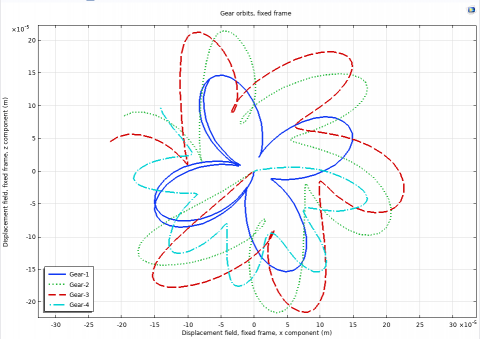
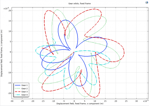
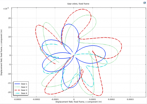
4.2 Helix angle effect on gear orbits
As for the effect of angles on the axial movement of the gears, it can be seen in Figure 4 that the value of the axial movement decreases gradually with the increase in angles and is less susceptible to uncoordinated movement, as in angle 40. It may be unsatisfactory in terms of axial movement.
So, angle 5 is the best angle because of its axial motion coordination and its non-deviation from the composition of the orbits in the remaining angles.
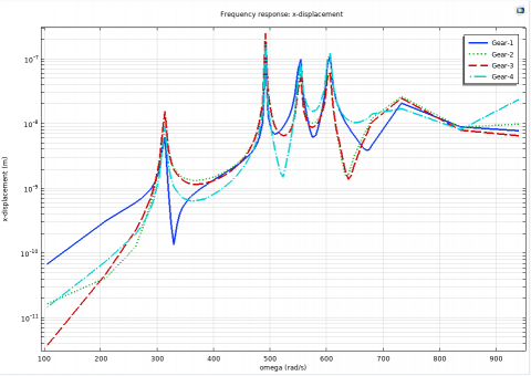
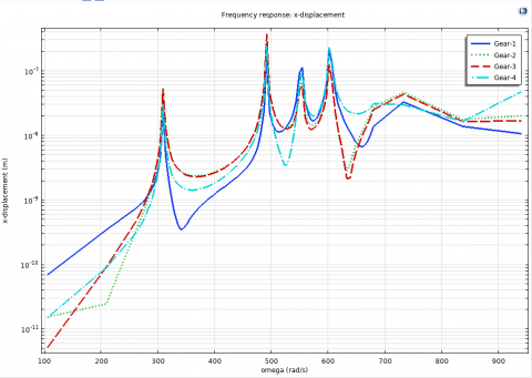
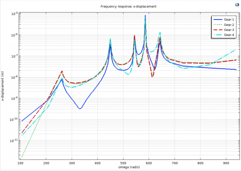
4.3 Helix angle effect on gear X-displacement
The vibration process as a result of the engagement of the gears loses its kinetic energy in a large way, which goes through heat or noise. Through Figure 5, he notices the movement of the axes from their center due to the spherical movement of the gears.
At angle degree 5, it is noted that the largest value of movement in the x axis was for gear 3 at a rotational speed of 590 rad/s, which reached 0.15 micrometers. At angle degree 10 and at the same gear and the same degree of rotation, the axial distortion value was 0.27 micrometers. At an angle of 20 degrees, the value of the rotational speed increased to 600 rad/s, and in the fourth gear, the deformation value was 0.56 micrometers. It may be noted that the large rise in angles 30 and 40 reached from angle 40 to 9 micrometers, which is relatively large compared to the remaining angles.
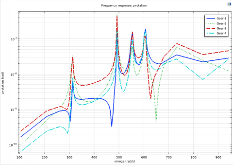
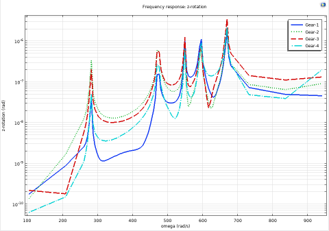
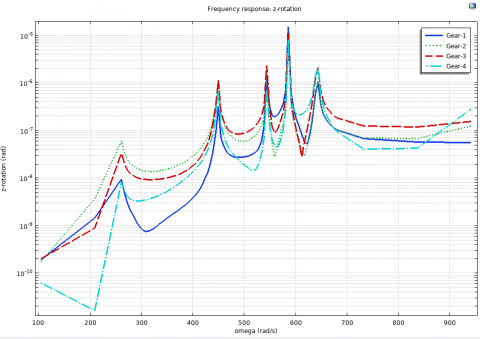
4.4 Helix angle effect on gear Z-rotation
With regard to the vertical rotation in the z axis, we may notice the same ascending features for the vertical rotational movement, where the 5 angles represent the best solutions for this movement compared to the remaining angles, as can be seen in Figure 6.
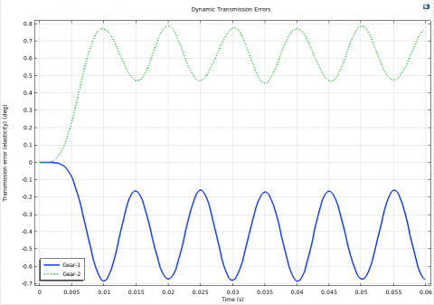
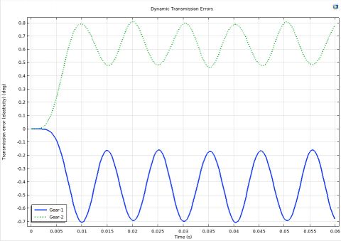
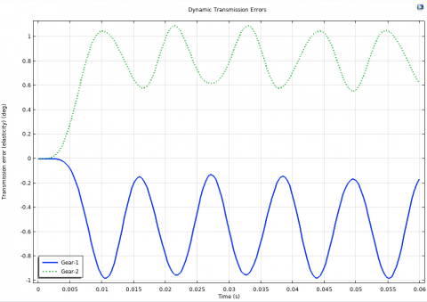
4.5 Helix angle effect on gear transmission error
The angles of the helix have a significant impact on the angle of error with the engagement of the gears, as Figure 7 gives clear evidence of the ratio of the engagement error between the small and large gears and the method of increasing and decreasing between them.
Where it was noticed that the lowest error percentage that can be obtained is at angle 5, whose maximum value is 0.8 degrees between the gears compared to the rest of the angles.
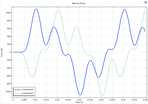
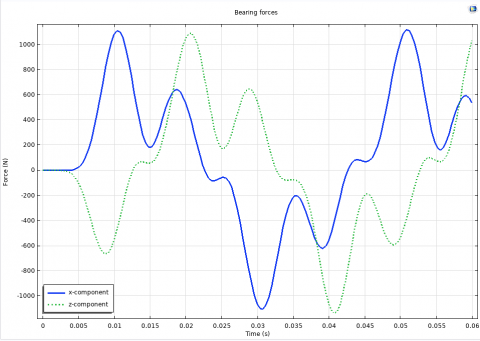
4.6 Helix angle effect on reaction force
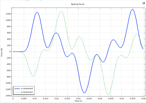
The most important part to be studied is the value of the influence of angles on the reaction force for the shaft. Through Figure 8, the results of the force acting on the shaft can be seen from two different axes and their change with time.
Where it was noticed that the lowest error percentage that can be obtained is at angle 5, whose maximum value is 0.8 degrees between the gears compared to the rest of the angles.
1. Some variables or mechanical phenomena are adversely affected by the helix angle, whereas others are positively affected. According to Figure 3, the stress value is distributed widely on the shaft in corners 5, 10, and 40, but less widely in corners 20 and 30. The stress is also dispersed across the final shaft, where it is relatively low compared to the other shafts. The ideal condition for helical gears is reported to be at an angle of 30, where the influence of strains on the shaft is minimal.
2. Regarding the impact of angles on the axial movement of the gears, Figure 4 illustrates how the axial movement value steadily reduces as the angle increases and becomes less vulnerable to ad hoc movements, such as angle 40. It may not provide appropriate axial mobility. Because of its axial motion coordination and lack of divergence from the orbital composition of the other angles, angle 5 is the optimum angle.
3. The vibration process caused by the engagement of the gears loses a significant amount of kinetic energy, which is transferred as heat or noise. Through Figure 5, it can see how the axes are moving away from their centers as a result of the gears' spherical motion. The maximum value of movement in the x axis was for gear 3 at a rotational speed of 590 rad/s, reaching 0.15 micrometers at angle degree 5, it is observed. The axial distortion value was 0.27 micrometers at angle degree 10, the same gear, and the same rate of rotation. At a 20-degree angle, the rotational speed climbed to 600 rad/s, and the deformation value was 0.56 micrometers in fourth gear. It should be noticed that the steep increase in angles 30 and 40 was rather considerable compared to the other angles, reaching from angle 40 to 9 micrometers.
4. As shown in Figure 6, the rising characteristics for the vertical rotational movement are the same for the vertical rotation in the z axis, with the 5 angles providing the best solutions for this movement when compared to the other angles.
5. Since Figure 7 shows the ratio of the engagement error between the small and big gears and the way of growing and decreasing between them, it is obvious that the angles of the helix have a major influence on the angle of error with the engagement of the gears. It was discovered that angle 5 has the lowest possible error %, with a maximum value of 0.8 degrees between the gears in comparison to the other angles.
6. The value of the effect of angles on the reaction force for the shaft is the most crucial factor to be investigated. Through Figure 8, the effects of the force acting on the shaft from two separate axes can be observed, along with how they change over time. The maximum response force at helix angle 5 is equal to 1080 N, but it grows as the helix angle value increases to reach 1450 N at angles 40 W. This clearly illustrates the benefit of helix angle 5 compared to the large escalation of angles.
1. The value of the stress has a large distribution on the shaft in corners 5, 10, and 40, but in corners 20 and 30, its distribution is less. Best condition reached in the angles of helical gears is 30, where effect of stresses on shaft is relatively small.
2. The orbits of the planets orbit Earth around a Sun-like star at an angle of about 5, rather than 40, as is usually the case, because of its axial motion coordination and its non-deviation from the composition of the orbits in the remaining angles.
3. At angle degree 5, the largest value of movement in the x axis was for gear 3 at a rotational speed of 590 rad/s, which reached 0.15 micrometers. The large rise in angles 30 and 40 reached from angle 40 to 9 micrometer is relatively large compared to the remaining angles.
4. With regard to the vertical rotation in the z axis, we may notice the same ascending features for the vertical rotational movement as we do for the horizontal rotation. The 5 angles represent the best solutions for this movement, and the remaining angles are the less attractive solutions.
5. The angles of the helix have a significant impact on the angle of error with the engagement of the gears and the ratio of the engagement error between the small and large gears. The lowest error percentage that can be obtained is at angle 5, whose maximum value is 0.8 degrees.
6. The helix angle 5 has a maximum reaction force equal to 1080 N, while it rises with an increase in the length of the helix. This gives clear evidence of the advantage of angles 5 compared to the escalation of angles significantly. The results of the force acting on the shaft can be seen from two different axes and their change with time.
The authors would like to thanks Al-Mustaqbal University College, 51001 Hillah, Babylon, Iraq for the assistance in completing this work.
[1] Chen, Z., Zeng, M., Fuentes-Aznar, A. (2020). Computerized design, simulation of meshing and stress analysis of pure rolling cylindrical helical gear drives with variable helix angle. Mechanism and Machine Theory, 153: 103962. https://doi.org/10.1016/j.mechmachtheory.2020.103962
[2] Mohanraj, R., Elangovan, S., Prakash, R.A., Sanjeev, S., Swetha, R., Agalya, K. (2020). Stress analysis on single and herringbone helical gears. Materials Today: Proceedings, 22: 2049-2057. https://doi.org/10.1016/j.matpr.2020.03.219
[3] Rai, P., Agrawal, A., Saini, M.L., Jodder, C., Barman, A. G. (2018). Volume optimization of helical gear with profile shift using real coded genetic algorithm. Procedia Computer Science, 133: 718-724. https://doi.org/10.1016/j.procs.2018.07.127
[4] Kim, S.C., Moon, S.G., Sohn, J.H., Park, Y.J., Choi, C.H., Lee, G.H. (2020). Macro geometry optimization of a helical gear pair for mass, efficiency, and transmission error. Mechanism and Machine Theory, 144: 103634. https://doi.org/10.1016/j.mechmachtheory.2019.103634
[5] Syzrantseva, K.V., Syzrantsev, V.N., Kolbasin, D.S. (2019). AIP Conference Proceedings [AIP Publishing MECHANICS, RESOURCE AND DIAGNOSTICS OF MATERIALS AND STRUCTURES (MRDMS-2019): -Ekaterinburg, Russia (9–13 December 2019)]: Proceedings of the 13th International Conference on Mechanics- Comparative estimation of the failure probability of cylindrical arc and helical gears by tooth bending endurance, 2176, 020010. https://doi.org/10.1063/1.5135122
[6] Zouridaki, A.E., Vasileiou, G. (2020). Investigation of the Effect of Geometry Characteristics on Bending Stress of Asymmetric Helical Gears by Using Finite Elements Analysis. Computation, 8(1): 19. https://doi.org/10.3390/computation8010019
[7] Patil, P.J., Patil, M., Joshi, K. (2018). Investigating the effect of helix angle and pressure angle on bending stress in helical gear under dynamic state. World Journal of Engineering, 15(4): 478-488. https://doi.org/10.1108/wje-06-2017-0134
[8] Zhan, J., Fard, M. (2018). Effects of helix angle, mechanical errors, and coefficient of friction on the time-varying tooth-root stress of helical gears. Measurement, 118: 135-146. https://doi.org/10.1016/j.measurement.2018.01.021
[9] Choi, C., Ahn, H., Park, Y.J., Lee, G.H., Kim, S.C. (2021). Influence of gear tooth addendum and dedendum on the helical gear optimization considering mass, efficiency, and transmission error. Mechanism and Machine Theory, 166: 104476. https://doi.org/10.1016/j.mechmachtheory.2021
[10] Rai, P., Barman, A.G. (2019). An approach for design optimization of helical gear pair with balanced specific sliding and modified tooth profile. Structural and Multidisciplinary Optimization, 60: 331-341. https://doi.org/10.1007/s00158-019-02198-7
[11] Patil, P.J., Patil, M.S., Joshi, K.D. (2019). Dynamic state or whole field analysis of helical gear. Journal of The Institution of Engineers (India): Series C, 100: 37-42. https://doi.org/10.1007/s40032-017-0389-3
[12] Shehata, A., Adnan, M.A., Mohammed, O.D. (2019). Modeling the effect of misalignment and tooth microgeometry on helical gear pair in mesh. Engineering Failure Analysis, 106: 104190. https://doi.org/10.1016/j.engfailanal.2019.104190
[13] Liu, Y., Zhao, Y., Liu, M., Sun, X. (2019). Parameterized high-precision finite element modelling method of 3D helical gears with contact zone refinement. Shock and Vibration, 2019: 1-17. https://doi.org/10.1155/2019/5809164
[14] Liu, C., Fang, Z., Wang, F. (2018). An improved model for dynamic analysis of a double-helical gear reduction unit by hybrid user-defined elements: Experimental and numerical validation. Mechanism and Machine Theory, 127: 96-111. https://doi.org/10.1016/j.mechmachtheory.2018.04.022
[15] Lin, C., Wei, W., Wang, S., Xia, X., Xin, Q. (2020). Bending stress analysis of eccentric straight and helical curve-face gear pair. International Journal of Mechanics and Materials in Design, 16: 401-414. https://doi.org/10.1007/s10999-019-09475-9
[16] Yan, P., Liu, H., Gao, P., Zhang, X., Zhan, Z., Zhang, C. (2021). Optimization of distributed axial dynamic modification based on the dynamic characteristics of a helical gear pair and a test verification. Mechanism and Machine Theory, 163: 104371. https://doi.org/10.1016/j.mechmachtheory.2021
[17] Chen, K., Ma, H., Che, L., Li, Z., Wen, B. (2019). Comparison of meshing characteristics of helical gears with spalling fault using analytical and finite-element methods. Mechanical Systems and Signal Processing, 121: 279-298. https://doi.org/10.1016/j.ymssp.2018.11.023
[18] Roda-Casanova, V., Gonzalez-Perez, I. (2021). Investigation of the effect of contact pattern design on the mechanical and thermal behaviors of plastic‐steel helical gear drives. Mechanism and Machine Theory, 164: 104401. https://doi.org/10.1016/j.mechmachtheory.2021
[19] Wei, J., Zhang, A., Wang, G., Qin, D., Lim, T.C., Wang, Y., Lin, T. (2018). A study of nonlinear excitation modeling of helical gears with modification: theoretical analysis and experiments. Mechanism and Machine Theory, 128: 314-335. https://doi.org/10.1016/j.mechmachtheory.2018.06.005
[20] Samya, B., Boudi, E.M., Bachir, A., Amadane, Y. (2020). Analysis of profile shift factor's effect on bending stress of spur gears using the finite element method. In 2020 IEEE 6th International Conference on Optimization and Applications (ICOA), pp. 1-6. https://doi.org/10.1109/ICOA49421.2020.9094486
[21] Godwin Raja Ebenezer, N., Ramabalan, S., Navaneethasanthakumar, S. (2022). Design optimisation of mating helical gears with profile shift using nature inspired algorithms. Australian Journal of Mechanical Engineering, 20(4): 903-910. https://doi.org/10.1080/14484846.2020.1761007
[22] Yamaoka, M., Tanaka, M., Kumada, M., Nojima, K., Nishi, R., Ono, Y., Koide, T. (2019). Bending fatigue strength of case-carburized helical gears with large helix angles up to 40 degrees. Journal of Mechanical Science and Technology, 33: 5699-5709. https://doi.org/10.1007/s12206-019-1113-4
[23] Feng, W., Feng, Z., Mao, L. (2020). Failure analysis of a secondary driving helical gear in transmission of electric vehicle. Engineering Failure Analysis, 117: 104934. https://doi.org/10.1016/j.engfailanal.2020.104934
[24] Mo, S., Zou, Z., Feng, Z., Dang, H., Gao, H., Cao, X. (2020). Research on lubrication characteristics of asymmetric helical gear based on CFD method. Lubrication Science, 32(6): 309-320. https://doi.org/10.1002/ls.1504
[25] Park, J., Seo, C., Boo, K., Kim, H. (2018). Geometry modification of helical gear for reduction of static transmission error. In MATEC Web of Conferences, 167: 02013. https://doi.org/10.1051/matecconf/201816702013