Kahina Berabez*![]() | Farid Hamoudi
| Farid Hamoudi![]() | Kassa Idjdarene
| Kassa Idjdarene![]() | Ismail Hacini
| Ismail Hacini![]()
© 2023 IIETA. This article is published by IIETA and is licensed under the CC BY 4.0 license (http://creativecommons.org/licenses/by/4.0/).
OPEN ACCESS
This study aims to improve the terminal voltage control of a self-excited induction generator (SEIG) that operates an independent load and is supplied by a wind turbine with variable speed. A three-level neutral point clamped (3L_NPC) converter employing direct torque control (DTC) is utilized to achieve this control. Two strategies are implemented: In the first strategy, the flux is maintained constant, while in the second, the flux varies with the speed. Voltage space vector selection is used to control the electromagnetic torque, stator flux, and induction generator, aiming to reduce torque and flux ripples. The three-level converter, as opposed to the two-level version, offers an increased degree of freedom in voltage vector selection, resulting in enhanced performance. The control strategy being suggested seeks to maintain a consistent voltage level across the DC bus, irrespective of fluctuations in load and wind speed one can effectively regulate the system, by controlling the torque according to the speed. A dynamic model accounting for the saturation effect of magnetic material is developed in the (α-β) frame using the Concordia transform. The effectiveness of the proposed control strategy is validated through simulation tests conducted in Matlab/Simulink.
DTC control, 3L_NPC converter, induction generator, saturation, autonomous
The utilization of wind turbines as a renewable energy source has experienced significant growth in recent years, particularly in isolated or remote areas [1, 2]. In these applications, squirrel cage induction generators are frequently employed due to their robustness and low cost [3, 4]. Self-excitation in these machines can be accomplished by either linking a capacitance bank to the stator terminals or employing an inverter/rectifier system with a single DC capacitor on the DC link side [5, 6]. However, maintaining high-quality power output, such as voltage and frequency, when powered by intermittent energy resources, presents a challenge that impacts the performance of self-excited induction generators (SEIGs) [6, 7]. Consequently, these generators require advanced control methods.
Various control strategies have been proposed in the literature to ensure desired regulation. Among them, Field Oriented Control treats the induction generator as a DC machine and is based on decoupling the flux and electromagnetic torque, requiring estimation of the controlled quantities (flux and electromagnetic torque) [8-10]. This decoupling enables a fast torque response. Direct torque control (DTC), introduced by Takahashi in the mid-1980s [11], has become one of the predominant used control methods for addressing the intricacy and restrictions of traditional controls and enhancing induction generator performance [7]. DTC offers several advantages, including good torque dynamic response, high resilience, minimal complexity, a simplified induction machine model, and no need for a current regulator, PWM modulation block, speed sensor, or coordinate transformation [12]. Despite these benefits, classical DTC exhibits some drawbacks, such as the difficult of control of the switching frequency, which can lead to commutation losses and current distortions that may have an impact on the quality of the output power, and significant torque and flux ripples caused by a hysteresis controller, which impact system performance [11, 13].
To address these issues, researchers have proposed various methods. Fuzzy logic regulators have been used instead of hysteresis regulators [12, 14, 15]. Ayrir and Haddi [14] and Sahri et al. [16]. To lessen flux fluctuations, the authors propose employing 12 sectors rather than six. A Predictive (P_DTC) control [17], and a (DTC_SVM) [13, 18], the SVM algorithm was used to replace the switching table, while PI controllers were employed in lieu of hysteresis comparators. Artificial Neural Networks (ANN) and fuzzy logic controllers were employed for improved DTC in induction motor (IM) control [19, 20].
Recently, many studies have focused on using multilevel converters as a substitute for two-level converters to overcome classical DTC problems, thanks to their benefits, such as reduced torque ripple, smoother waveforms, lower THD values for stator current, and power segmentation [15, 19, 21, 22]. These approaches have demonstrated good performance in controlling induction machines in motor operation, and many works have also been based on doubly fed induction motor/generator using more advanced strategies. In this study, the focus is on controlling a SEIG through a three-level 3L-NPC converter using DTC control technique. It is important to note that this control strategy takes into consideration the saturation effect of the SEIG, which is accounted for by the magnetization inductance Lm. The representation of Lm is approximated using a polynomial function of the magnetization current im.
The primary objective of this work is to evaluate the performance of this control under two strategies that depend on the reference value of stator flux. In the first strategy, the reference flux is held constant, whereas in the second strategy, the flux varies according to the driving speed. As a result, the first strategy maintains a constant saturation level of the induction generator independent of the speed, while the second strategy allows for a variable saturation level. The latter strategy is more suitable for high-speed operation, as it reduces the saturation level in the induction generator. The simulation results are presented, discussed, and analyzed using the MATLAB/SIMULINK environment.
The main elements of the studied system are: a wind turbine, a squirrel cage three-phase induction generator, autonomous load which is powered by a converter (3L_NPC) a DC side which includes a capacitor and a start-up battery provide the initial voltage to the capacitor and also to start the excitation process. The global scheme and control strategy of the system studied in this work is shows Figure 1.
Figure 1. System and DTC strategy scheme
2.1 Induction machine model
To implementation of DTC strategy, the dynamic model of model of the induction machine in the (α-β) frame should be established. The electrical equations of this model are written by following:
$\left[\begin{array}{c}V_{s \alpha} \\ V_{s \beta} \\ 0 \\ 0\end{array}\right]=\left[\begin{array}{cccc}R_s & 0 & 0 & 0 \\ 0 & R_s & 0 & 0 \\ -R_r & \omega_r \cdot l_r & R_T & -\omega_r \cdot\left(l_r+L_m\right) \\ -\omega_r \cdot l_r & -R_r & \omega_r \cdot\left(l_r+L_m\right) & R_r\end{array}\right] \cdot\left[\begin{array}{c}i_{s \alpha} \\ i_{s \beta} \\ i_{m \alpha} \\ i_{m \beta}\end{array}\right]+$$\left[\begin{array}{cccc}l_s & 0 & L_m+L_m^{\prime} \cdot \frac{i_{m \alpha}{ }^2}{\left|i_m\right|} & L_m^{\prime} \cdot \frac{i_{m \alpha} \cdot i_{m \beta}}{\left|i_m\right|} \\ 0 & l_s & L_m^{\prime} \cdot \frac{i_{m \alpha} \cdot i_{m \beta}}{\left|i_m\right|} & L_m+L_m^{\prime} \cdot \frac{i_{m \beta}{ }^2}{\left|i_m\right|} \\ -l_r & 0 & l_r+L_m+L_m^{\prime} \cdot \frac{i_{m \alpha}{ }^2}{\left|i_m\right|} & L_m \cdot \frac{i_{m \alpha} \cdot i_{m \beta}}{\left|i_m\right|} \\ 0 & -l_r & L_m^{\prime} \cdot \frac{i_{m \alpha} \cdot i_{m \beta}}{\left|i_m\right|} & l_r+L_m+L_m \cdot \frac{i_{m \beta}{ }^2}{\left|i_m\right|}\end{array}\right]$$\cdot$ $\left[\begin{array}{c}\frac{d i_{s \alpha}}{d t} \\ \frac{d i_{s \alpha}}{d t} \\ \frac{d i_{m \alpha}}{d t} \\ \frac{d i_{m \beta}}{d t}\end{array}\right]$ (1)
where, vsα and vsβ, representing the stator voltages, while isα and isβ represent the stator currents in in (α, β) reference frame.
The magnetizing currents, referred to as imα and imβ, are determined along the α and β axes respectively.
$\left\{\begin{array}{l}i_{m \alpha}=i_{s \alpha}+i_{r \alpha} \\ i_{m \beta}=i_{s \beta}+i_{r \beta}\end{array}\right.$ (2)
irα and irβ: represent the α-β rotor currents.
The magnetizing current im is defined as:
${{i}_{m}}=\sqrt{{{i}_{m\alpha }}^{2}+{{i}_{m\beta }}^{2}}$ (3)
ωr: is the rotor angular speed.
With ${{\omega }_{r}}=p\Omega $ (4)
Besides, Rs, ls, Rr and lr are the stator and rotor phase resistances and leakage inductances respectively. Lm is the magnetizing inductance.
The saturation effect is taken into account by the expression of the magnetizing inductance Lm with respects to im with using a polynomial approximation, of degree 12 [6]. The Lmwith respects to im, is given by the following equation:
$\left\{ \begin{matrix} {{L}_{m}}\,=\,f\left( \left| i_{m}^{{}} \right| \right)\,=\,\sum\limits_{j=0}^{n}{a_{j}^{{}}\,.\,\left| i_{m}^{{}} \right|_{{}}^{j}}\begin{matrix} {} & {} & {} \\\end{matrix}\begin{matrix} {} & {} & {} \\\end{matrix} \\ {} \\ {{L}_{m}}_{{}}^{'}\,=\frac{d{{L}_{m}}}{d\left| i_{m}^{{}} \right|}\,=\,\frac{d}{d\left| i_{m}^{{}} \right|}f\left( \left| i_{m}^{{}} \right| \right)\,=\,\sum\limits_{j=0}^{n}{j\,.\,a_{j}^{{}}\,.\,\left| i_{m}^{{}} \right|_{{}}^{j-1}} \\\end{matrix} \right.$ (5)
The different parameters of the studied squirrel induction machine are given in appendix.
Figure 2. Schematic of a three-level NPC inverter
2.2 Three-level NPC converter and DC link mode
Figure 2 displays the schematic diagram of a 3L_NPC. This converter comprises a DC-link capacitor, twelve fully-controlled switches, each accompanied by a freewheeling diode, as well as two power diodes situated in each phase leg. These components enable the connection of the phase output to the midpoint of the DC bus. The twelve switches, organized in four switches per leg, as specified in Table 1 [15], allow the generation of three levels of output voltages: Udc/2, 0, and -Udc/2, through their combinations.
Table 1. Switching states
|
$\boldsymbol{S}_{j 1}$ |
$\boldsymbol{S}_{x j 2}$ |
$\overline{S_{j 1}}$ |
$\overline{S_{j 2}}$ |
$\boldsymbol{S}_j$ |
$v_{j 0}$ |
|
1 |
1 |
0 |
0 |
P |
Udc/2 |
|
0 |
1 |
1 |
0 |
O |
0 |
|
0 |
0 |
1 |
1 |
N |
-Udc/2 |
A connection function Sji is defined for every switch Tji:
$\left\{ \begin{matrix} {{S}_{xi}}=1\,\,\,\,if\,\,\,{{k}_{xi\,\,\,\,}}closed \\ {{S}_{xi}}=0\,\,\,\,if\,\,\,{{k}_{xi\,\,\,\,}}open \\\end{matrix} \right.$ (6)
With j=a, b, c and i=1,2,3,4.
The following equation defines a connection function $F_j^h$ which is associated with every state h of the arm x [15]:
$\left\{ \begin{matrix} F_{x}^{2}={{S}_{x1}}\,{{S}_{x2}} \\ F_{x}^{1}={{S}_{x1}}\overline{\,{{S}_{x2}}} \\ F_{x}^{0}=\overline{{{S}_{x1}}}\overline{\,{{S}_{x2}}} \\\end{matrix} \right.$ (7)
The connection functions are used to express the three voltage levels as depicted in the following equation:
${{v}_{xo}}={{V}_{dc}}(F_{x}^{2}\,-F_{x}^{0})$ (8)
The voltages of the legs can subsequently be expressed as stated in the study [16]:
$\left[\begin{array}{c}v_a \\ v_b \\ v_c\end{array}\right]=\frac{V_{d c}}{3}\left[\begin{array}{ccc}2 & -1 & -1 \\ -1 & 2 & -1 \\ -1 & -1 & 2\end{array}\right]\left[\begin{array}{c}F_a^2-F_a^0 \\ F_b^2-F_b^0 \\ F_c^2-F_c^0\end{array}\right]$ (9)
The input currents of the three-phase inverter are expressed as follows:
$\left\{ \begin{matrix} {{i}_{d2}}=F_{a}^{2}\,{{i}_{a}}+F_{b}^{2}\,{{i}_{b}}+F_{c}^{2}\,{{i}_{c}} \\ \begin{align} & {{i}_{d1}}=F_{a}^{1}\,{{i}_{a}}+F_{b}^{1}\,{{i}_{b}}+F_{c}^{1}\,{{i}_{c}} \\ & {{i}_{d0}}=F_{a}^{0}\,{{i}_{a}}+F_{b}^{0}\,{{i}_{b}}+F_{c}^{0}\,{{i}_{c}} \\\end{align} \\\end{matrix} \right.$ (10)
The following equations presents relationship between the capacitor currents and the alternating currents:
$\left[ \begin{align} & {{i}_{c1}} \\ & {{i}_{c2}} \\\end{align} \right]=\frac{1}{2}\left[ \begin{matrix} F_{a}^{1} & F_{b}^{1} & F_{c}^{1} \\ -F_{a}^{1} & -F_{b}^{1} & -F_{c}^{1} \\\end{matrix} \right]\,\,\left[ \begin{matrix} {{i}_{a}} \\ {{i}_{b}} \\ {{i}_{c}} \\\end{matrix} \right]$ (11)
The equation provides the expression for the in current:
${{i}_{dc}}={{i}_{b}}-{{i}_{R}}-{{i}_{c}}$ (12)
With ${{i}_{c}}=C\frac{d{{V}_{dc}}}{dt}$ (13)
The equation below represents the DC voltage:
${{V}_{dc}}=-\int{\frac{1}{C}\left( {{i}_{dc}}+{{V}_{dc}}\left( \frac{1}{R}+\frac{1}{{{r}_{b}}} \right)-\frac{{{V}_{0}}}{{{r}_{b}}} \right)}$ (14)
where, V0 denotes the initial voltage across the capacitor, equivalent to the voltage of the battery.
Table 2. DTC switching table 27 vectors
|
eφ |
eTem |
Sectors Zn |
|||||||||||
|
Z1 |
Z2 |
Z3 |
Z4 |
Z5 |
Z6 |
Z7 |
Z8 |
Z9 |
Z10 |
Z11 |
Z12 |
||
|
1 |
+2 |
V17 |
V23 |
V18 |
V24 |
V19 |
V25 |
V20 |
V26 |
V15 |
V21 |
V16 |
V22 |
|
+1 |
V03 |
V23 |
V04 |
V24 |
V05 |
V25 |
V06 |
V26 |
V01 |
V21 |
V02 |
V22 |
|
|
0 |
V00 |
V07 |
V14 |
V00 |
V07 |
V14 |
V00 |
V07 |
V14 |
V00 |
V07 |
V14 |
|
|
-1 |
V05 |
V25 |
V06 |
V26 |
V01 |
V21 |
V02 |
V22 |
V03 |
V23 |
V04 |
V24 |
|
|
-2 |
V19 |
V25 |
V20 |
V26 |
V15 |
V21 |
V16 |
V22 |
V17 |
V21 |
V18 |
V24 |
|
|
0 |
+2 |
V22 |
V17 |
V23 |
V18 |
V24 |
V19 |
V25 |
V20 |
V26 |
V15 |
V21 |
V16 |
|
+1 |
V22 |
V03 |
V23 |
V04 |
V24 |
V05 |
V25 |
V06 |
V26 |
V01 |
V21 |
V02 |
|
|
0 |
V00 |
V07 |
V14 |
V00 |
V07 |
V14 |
V00 |
V07 |
V14 |
V00 |
V07 |
V14 |
|
|
-1 |
V25 |
V06 |
V26 |
V01 |
V21 |
V02 |
V22 |
V03 |
V23 |
V04 |
V24 |
V05 |
|
|
-2 |
V25 |
V20 |
V26 |
V15 |
V21 |
V16 |
V22 |
V17 |
V23 |
V18 |
V24 |
V19 |
|
|
-1 |
+2 |
V21 |
V16 |
V22 |
V17 |
V23 |
V18 |
V24 |
V19 |
V25 |
V20 |
V26 |
V15 |
|
+1 |
V21 |
V02 |
V22 |
V03 |
V23 |
V04 |
V24 |
V05 |
V25 |
V06 |
V26 |
V01 |
|
|
0 |
V00 |
V07 |
V14 |
V00 |
V07 |
V14 |
V00 |
V07 |
V14 |
V00 |
V07 |
V14 |
|
|
-1 |
V26 |
V01 |
V21 |
V02 |
V22 |
V03 |
V23 |
V04 |
V24 |
V05 |
V25 |
V06 |
|
|
-2 |
V26 |
V15 |
V21 |
V16 |
V22 |
V17 |
V23 |
V18 |
V24 |
V19 |
V25 |
V20 |
|
Upon the diode being in a blocked state, the DC voltage attains a value of Udc≥U0. Consequently, the DC current and voltage become, respectively:
${{i}_{dc}}=-{{i}_{R}}-{{i}_{c}}$ (15)
${{V}_{dc}}=-\int{\frac{1}{C}\left( {{i}_{dc}}+\frac{{{V}_{dc}}}{R} \right)}$ (16)
The selection of converter switching states can be made from a switching table (refer to Table 2) [11, 23]. This table determines the set of 27 optimal voltage vectors that need to be applied to the converter at each switching instant.
2.3 Direct torque control strategy
Direct torque control (DTC) aims to directly regulate the torque of the machine, by applying the various voltage vectors of the inverter. The controlled variables are the stator flux and the electromagnetic torque which are usually controlled by hysteresis regulators. It is a matter of keeping these two instantaneous quantities with in a band around the desired value [15]. The output of these regulators determines the optimal inverter voltage vector to be applied at each switching instant. The improvement of the DTC with the use of NPC is shown in this part, because this command in case the two-level converters are used, the error information of torque and flux are directly implemented to choose the switching state without distinguishing the degree between very large or relatively small error. This obviously produces an imprecise response, the performance of the system can be improved if the level degree of the inverters used is increased in order to have a wide range of selection of the voltage vectors based on the level of variation observed in the error values of torque and flux [15, 24]. Thus, the partition of the position of the flux under numerous zones (sectors), allows us to have a considerable efficiency of control at the level of the new switching algorithm. To ensure a more precise control, the space of flux evolution is divided into twelve sectors (1...12), each spanning 30 degrees. This selection is made with the intention of enhancing the overall control accuracy:
$\frac{-\pi }{12}+(i-1)\frac{\pi }{6}\le S(i)\prec \frac{\pi }{12}+(i-1)\frac{\pi }{6}$ (17)
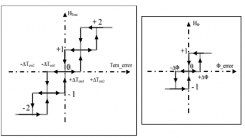
The five-level hysteresis comparator is using for controlled the electromagnetic torque, while the stator flux is controlled by the three-level hysteresis comparators as shown in the following Figure 3.
Figure 3. The hysteresis controllers used to control the electromagnetic torque and stator flux
The inputs of hysteresis controllers are errors (eφsd & eTem) which are found after the comparison between the estimated values (φsd & Tem) of the stator flux amplitude and the electromagnetic torque respectively and their reference signals (φsd_ref & Tem_ref). while the outputs variables of the controllers are combined while the outputs variables of the controllers are combined with the position of the stator flux vector (Zn) to form out the inputs to the switching table.
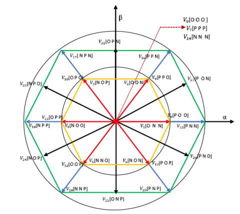
The set of voltage vectors delivered by a three-level converter (NPC) as well as the sequences of corresponding phase levels are represented by the space vector diagram as shown in Figure 4.
Figure 4. Space voltage vector of 3L-NPC inverter with their switching states [23]
The vector representation of the SEIG serves to highlight the dynamic control requirements for the electromagnetic torque of the induction machine. In order to achieve this, we present the electrical equations of the machine within the spatial vector [7]:
$\begin{align} & \overline{{{V}_{s}}}={{R}_{s}}\overline{{{I}_{s}}}+\frac{d\overline{{{\Phi }_{s}}}}{dt} \\ & 0={{R}_{r}}\overline{{{I}_{r}}}+\frac{d\overline{{{\Phi }_{r}}}}{dt}-j\omega \overline{{{\Phi }_{r}}} \\\end{align}$ (18)
The voltage vector Vs, which is supplied by a 3L_NPC converter, can be expressed using the connection functions in the following form [7]:
$\overline{{{V}_{s}}}=\sqrt{\frac{3}{2}}{{V}_{dc}}({{S}_{a}}+{{S}_{b}}^{j\frac{2\pi }{3}}+{{S}_{c}}^{j\frac{4\pi }{3}})$ (19)
2.4 Stator flux and torque estimation
It is worthy noted that the stationary reference frame has using for estimating the stator flux and Tem from the expressions of stator current and stator voltage, which are given by the following equations [7]:
$\left\{ \begin{align} & {{i}_{s\alpha }}=\sqrt{\frac{3}{2}}{{i}_{sa}} \\ & {{i}_{s\beta }}=\sqrt{\frac{1}{2}}({{i}_{sb}}-{{i}_{sc}}) \\\end{align} \right.$ (20)
$\left\{ \begin{align} & {{V}_{s\alpha }}=\sqrt{\frac{3}{2}}{{V}_{dc}}({{S}_{a}}-\frac{1}{2}({{S}_{b}}-{{S}_{c}})) \\ & {{V}_{s\beta }}=\sqrt{\frac{1}{2}}{{V}_{dc}}({{S}_{b}}-{{S}_{c}}) \\\end{align} \right.$ (21)
The magnitude of the stator flux can be expressed as follows:
${{\Phi }_{s}}=\sqrt{\Phi _{s\alpha }^{2}+\Phi _{s\beta }^{2}}$ (22)
where,
$\left\{ \begin{align} & {{\Phi }_{s\alpha }}=\int\limits_{0}^{t}{({{V}_{s\alpha }}-{{R}_{s}}{{i}_{s\alpha }})dt} \\ & {{\Phi }_{s\beta }}=\int\limits_{0}^{t}{({{V}_{s\beta }}-{{R}_{s}}{{i}_{s\beta }})dt} \\\end{align} \right.$ (23)
The equation of the electromagnetic torque is given from the stator flux $\left(\Phi_{s \alpha}, \Phi_{s \beta}\right)$ components and the stator current $\left(I_{s \alpha}, I_{s \beta}\right)$ as [7]:
${{T}_{em}}=p({{\Phi }_{s\alpha }}{{i}_{s\beta }}-{{\Phi }_{s\beta }}{{i}_{s\alpha }})$ (24)
In this work two strategies are studied, depends on the reference value of stator flux. The stator flux reference is effectively taken constant, equal to the nominal value, in the first strategy, i.e.:
${{\Phi }_{s\_ref}}={{\Phi }_{s\_nom}}=0.7Wb$ (25)
In the second technique, the reference of the stator flux is taken that is inversely proportional to the rotational speed, as determined by the following relationship:
${{\Phi }_{s\_ref}}=\frac{{{\omega }_{nom}}}{\omega }{{\Phi }_{s\_nom}}$ (26)
In this section, the simulation tests were conducted using the MATLAB®-SIMULINK environment of the whole system shown in Figure 4 are presented and commented. All the simulation test were carried during 10 sec. The sampling time for the control loop in all simulations is 10μs. The DTC control strategy is applied in the case of squirrel cage induction machine whose main parameters are shown in Table 3.
Table 3. Induction machine characteristics
|
Parameter |
Value |
|
Rated power |
5.5 kW |
|
Rated voltage and current |
230/400 V 23.8/13.7 A |
|
Frequency |
50 Hz |
|
Rotation speed |
690 rpm |
|
Inertia |
0.230 kg.m2 |
|
Friction |
0.0025 N.m/rads-1 |
|
Stator resistance Rs |
1.07131 W |
|
Rotor resistance Rr |
1.29511 W |
|
Number of pair of poles |
4 |
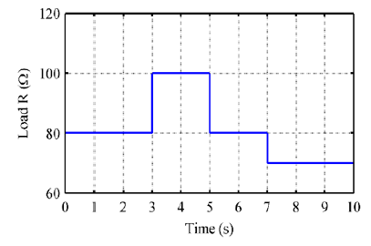
The performance of the system and its control are highlighted during the tests under variation of rotation speed and load changes. During the start-up phase, the induction generator is initially driven at a synchronous speed. Subsequently, a variation is introduced according to the speed profile illustrated in Figure 5. Additionally, a load variation is applied in accordance with the following load profile shown in Figure 6.
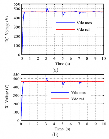
In the following, the DC voltage reference is maintained at a fixed value of 465V, while we set the flux reference to 0.7Wb in the first strategy, (Eq. (25)) and for the second strategy the stator flux is variable according to the driving speed (Eq. (26)). Here after is a presentation and discussion of the results obtained; remark that figures noted with the letter (a) relate to the results obtained by the first strategy, while the figures noted with the letter (b) show the results with the second strategy, in order to be able to compare performance under the same conditions.
Figures 7(a) and (b) show that whatever the adopted strategy, the DC bus voltage perfectly follows its reference value with the speed variations and a slight overshoot that does not exceed 5% during all load variations. Nonetheless, these disturbances are rapidly attenuated and rejected.
Figure 5. Profile of rotation speed
Figure 6. Profile of changes in load
Figure 7. DC bus voltage
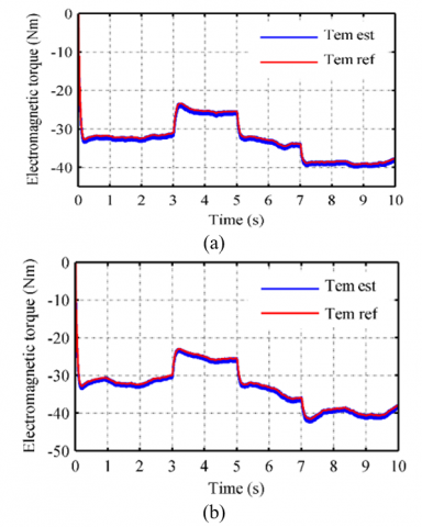
Figure 8. The progression of the electromagnetic torque over time
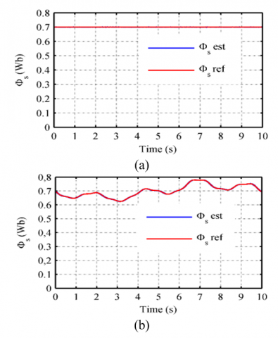
Figure 9. The stator flux magnitude
Figure 8 is shown the progression of the electromagnetic torque in response to both speed and load variations. It can be seen that the torque Tem is influenced by these variations, but clearly, with similar way for both strategies. The stator flux magnitude is presented in Figure 9(a) for the first strategy i.e., with fixed flux value (Φs_ref=0.7Wb), and Figure 9(b) for the second strategy, i.e., with variable flux. The estimated flux accurately follows its reference without exhibiting any overshoot, remaining unaffected by both speed and load variations.
Figure 10. Stator flux trajectory
Figure 11. The evolutions of the flux (φsα, φsβ)
In both strategies, the variations of the flux Φsβ in relation to Φsα, as illustrated in Figure 10, exhibits a perfectly circular shape. The radius of that circle does not exceed the flux nominal value, i.e., 0.7 Wb with the first strategy (fixed flux). The flux took a few steps before reaching the reference flux magnitude (0.7 Wb) and it not follows speed variations in the first case. In the case of the second strategy, the variation of the flux is proportional to the variation of the speed. According to the relationship (26), this is entirely expected. The variations of the flux components (φsα, φsβ) exhibit sinusoidal waveforms, as depicted in Figure 11 and the magnitudes of this sinewaves follow the one of the stator flux.
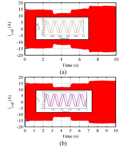
Regarding the stator, current, in Figure 12, one can see that the component of this current in (α, β) reference frame, have a sinusoidal form.
Figure 12. The evolutions of the flux (isα, isβ)
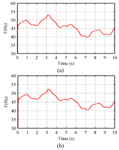
In Figure 13, this current is represented in abc-frames. Naturally, this current follows the speed and load changes. Moreover, its shape is sinusoidal, as shown in the zoom. Furthermore, the stator currents demonstrate a lack of harmonic components, as evidenced by the spectrum presented in Figure 14. The THD is measured to be 0.71%. The histogram in the Figure 15 indicates the THD values of these currents measured at different times according to the variations applied for the two strategies. It can be noted that the THD in the second strategy is considerably reduced in comparison with the first strategy. The stator frequency is given in the Figure 16; it seems clearly that this frequency is more sensitive to the speed that to the load change.
Figure 13. The stator current
Figure 14. The spectral analysis (THD)
Figure 15. THD values
Figure 16. Frequency
The magnetization inductance Lm evolution is not the same for both strategies, and that represent the level of the saturation phenomenon of the induction generator, as illustrated in Figure 17.
Figure 18 is represented the voltage vector trajectory in (α, β), The vector projections show us in a clearer way the vectors of voltages selected with the DTC control using the 3L_NPC rectifier.
Figure 17. The magnetization inductance Lm
Figure 18. The trajectory of the voltage
The objective of this paper is to enhance the performance of the SEIG in an autonomous wind system with variable speed. This is achieved by implementing direct torque control with the utilization of a three-level rectifier. The diphase analytical model of the induction generator, in the reference frame (α, β), is introduced taking into account the saturation effect by means of a variable magnetizing inductance. Two strategies of flux control are proposed; in the first strategy the flux is maintain constant. In the second strategy the stator flux is variable according to the driving speed.
The obtained simulation results demonstrate the effectiveness of the proposed (3L_NPC-DTC) control applied to the studied system. This control ensures better dynamic performance of a stand-alone induction generator and guarantees good regulation of the DC voltage and flux. Also, the studied system ensures significant reduction in torque and flux ripples with the two strategies, the THD of stator currents in the second strategy is considerably reduced in comparison with the first strategy.
The project presented in this paper is supported by the Laboratory of Industrial Technology and the Information (LTII) of Bejaia University under the patronage of the General Directorate of Scientific Research and Technological Development (DGRSDT), Algeria.
|
C |
capacitor |
|
$F_x^h$ |
connection function |
|
ia,b,c |
alternating stator currents |
|
ic1, c2 |
current flow onto a capacitors C1 and C2 |
|
iD |
current flow onto a diode D |
|
id0,d1,d2 |
inverter input currents |
|
idc |
DC bus current |
|
im |
magnetizing current |
|
iR |
current flow onto a resistance R |
|
Lm |
magnetizing inductance |
|
ls |
stator phase leakage inductances |
|
lr |
rotor phase leakage inductances |
|
R |
resistance |
|
rb |
battery resistance |
|
Rr |
rotor phase resistance |
|
Rs |
Stator phase resistance |
|
S(i) |
Sector |
|
sxi |
Connection function |
|
Tem-ref |
Electromagnetic torque reference |
|
Tem |
Electromagnetic torque |
|
va,b,c |
Alternating stator voltages |
|
Vdc |
DC bus voltage |
|
Vdc-ref |
DC bus voltage reference |
|
V0 |
Initial voltage across the capacitor (i.e., the battery voltage) |
|
vxo |
voltage between the capacitor mid-point and phase x |
|
Greek symbols |
|
|
vsα,sβ |
(α-β) axis components of the stator voltages |
|
isα,sβ |
(α-β) axis components of the stator currents |
|
irα,rβ |
(α-β) axis components of the rotor currents |
|
imα,mβ |
(α-β) axis components of the magnetizing currents |
|
φsα,sβ |
component of stator flux in the (α, β) reference frame |
|
φs_nom |
nominal value of stator flux |
|
φsd_ref |
stator flux reference |
|
∆Tem |
electromagnetic torque error |
|
Subscripts |
|
|
ANN |
Artificial Neural Networks |
|
DC |
Direct Current |
|
DTC |
Direct Torque Control |
|
SVM |
Space Vector Modulation |
|
IM |
Induction Motor |
|
P_DTC |
Predictive Direct Torque Control |
|
PI |
Proportional Integral |
|
PWM |
Pulse Width Modulation |
|
SEIG |
Self-Excited Induction Generator |
|
THD |
Total Harmonic Distortion |
|
3L_NPC |
Three-Level Neutral Point Clamped |
MATLAB®-SIMULINK (Licence number: 2731703).
[1] Na, W., Muljadi, E., Han, S., Tagayi, R.K., Kim, J. (2021). Possibility of power electronics-based control analysis of a self-excited induction generator (seig) for wind turbine and electrolyzer application. Electronics, 10(22): 2743. https://doi.org/10.3390/electronics10222743
[2] Saihi, L., Berbaoui, B., Glaoui, H., Djilali, L., Abdeldjalil, S. (2020). Robust sliding mode H∞ controller of DFIG based on variable speed wind energy conversion system. Periodica Polytechnica Electrical Engineering and Computer Science, 64(1): 53-63. https://doi.org/10.3311/PPee.14490
[3] Meena, D.C., Singh, M., Giri, A.K. (2021). Leaky-momentum control algorithm for voltage and frequency control of three-phase SEIG feeding isolated load. Journal of Engineering Research, ICARI Special Issue, 109-120. https://doi.org/10.36909/jer.ICARI.15335
[4] Laddi, T., Taib, N., Aouzellag, D. (2020). A proposed strategy for power management of a standalone wind energy conversion system with storage battery. Periodica Polytechnica Electrical Engineering and Computer Science, 64(3): 229-238. https://doi.org/10.3311/PPee.15094
[5] Seyoum, D., Rahman, M. F., Grantham, C. (2003, October). Inverter supplied voltage control system for an isolated induction generator driven by a wind turbine. In 38th IAS Annual Meeting on Conference Record of the Industry Applications Conference, Lake City, USA, pp. 568-575. https://doi.org/10.1109/IAS.2003.1257557
[6] Aberbour, A., Idjdarene, K., Tounzi, A. (2020). Performance analysis of self-excited induction generator mathematical dynamic model with magnetic saturation, cross saturation effect and iron losses. Mathematical Modelling of Engineering Problems, 7(4): 527-538. https://doi.org/10.18280/mmep.070404
[7] Idjdarene, K., Rekioua, D., Rekioua, T., Tounzi, A. (2009). Direct torque control strategy for a variable speed wind energy conversion system associated to a flywheel energy storage system. In 2009 Second International Conference on Developments in eSystems Engineering, Dhabi, United Arab Emirates, pp. 17-22. https://doi.org/10.1109/DeSE.2009.47
[8] Bendjeddou, Y., Deboucha, A., Bentouhami, L., Merabet, E., Abdessemed, R. (2021). Super twisting sliding mode approach applied to voltage orientated control of a stand-alone induction generator. Protection and Control of Modern Power Systems, 6(1): 18. https://doi.org/10.1186/s41601-021-00201-2
[9] Bašić, M., Vukadinović, D., Grgić, I., Bubalo, M. (2019). Energy efficient control of a stand-alone wind energy conversion system with AC current harmonics compensation. Control Engineering Practice, 93: 104185. https://doi.org/10.1016/j.conengprac.2019.104185
[10] Domínguez-García, J.L., Gomis-Bellmunt, O., Trilla-Romero, L., Junyent-Ferré, A. (2012). Indirect vector control of a squirrel cage induction generator wind turbine. Computers & Mathematics with Applications, 64(2): 102-114. https://doi.org/10.1016/j.camwa.2012.01.021
[11] El Ouanjli, N., Derouich, A., El Ghzizal, A., Motahhir, S., Chebabhi, A., El Mourabit, Y., Taoussi, M. (2019). Modern improvement techniques of direct torque control for induction motor drives-a review. Protection and Control of Modern Power Systems, 4(1): 11. https://doi.org/10.1186/s41601-019-0131-7
[12] Dagang, C.T.S., Kenne, G., Muluh, F.A. (2021). Fuzzy logic direct torque/power control for a self-excited induction generator driven by a variable wind speed turbine. International Journal of Dynamics and Control, 9: 1210-1222. https://doi.org/10.1007/s40435-020-00709-9
[13] Mesloub, H., Boumaaraf, R., Benchouia, M.T., Goléa, A., Goléa, N., Srairi, K. (2020). Comparative study of conventional DTC and DTC_SVM based control of PMSM motor—Simulation and experimental results. Mathematics and Computers in Simulation, 167: 296-307.https://doi.org/10.1016/j.matcom.2018.06.003
[14] Ayrir, W., Haddi, A. (2019). Fuzzy 12 sectors improved direct torque control of a DFIG with stator power factor control strategy. International Transactions on Electrical Energy Systems, 29(10): e12092. https://doi.org/10.1002/2050-7038.12092.
[15] Aissa, O., Moulahoum, S., Kabache, N., Houassine, H. (2014). Improvement of DTC of induction motors by using a three-level inverter and fuzzy speed controller. In 22nd Mediterranean Conference on Control and Automation, Palermo, Italy, pp. 73-78. https://doi.org/10.1109/MED.2014.6961329
[16] Sahri, Y., Tamalouzt, S., Lalouni Belaid, S., Bacha, S., Ullah, N., Ahamdi, A.A.A., Alzaed, A.N. (2021). Advanced fuzzy 12 dtc control of doubly fed induction generator for optimal power extraction in wind turbine system under random wind conditions. Sustainability, 13(21): 11593. https://doi.org/10.3390/su132111593
[17] Mokhtari, M., Davari, S.A. (2016). Predictive torque control of DFIG with torque ripple reduction. In 2016 IEEE International Conference on Power and Energy (PECon), Melaka, Malaysia, pp. 763-768. https://doi.org/10.1109/PECON.2016.7951661
[18] Mehedi, F., Yahdou, A., Djilali, A.B., Benbouhenni, H. (2020). Direct torque fuzzy controlled drive for multi-phase IPMSM based on SVM technique. Journal Européen des Systémes Automatisées, 53(2): 259-266. https://doi.org/10.18280/jesa.530213
[19] Benbouhenni, H. (2018). Seven-level direct torque control of induction motor based on artificial neural networks with regulation speed using fuzzy PI controller. Iranian Journal of Electrical and Electronic Engineering, 14(1): 85-94. https://doi.org/10.22068/IJEEE.14.1.85
[20] Fahassa, C., Zahraoui, Y., Akherraz, M., Kharrich, M., Elattar, E.E., Kamel, S. (2022). Induction motor DTC performance improvement by inserting fuzzy logic controllers and twelve-sector neural network switching table. Mathematics, 10(9): 1357. https://doi.org/10.3390/math10091357
[21] Hakami, S.S., Alsofyani, I.M., Lee, K.B. (2019). Torque ripple reduction and flux-droop minimization of DTC with improved interleaving CSFTC of IM fed by three-level NPC inverter. IEEE Access, 7: 184266-184275. https://doi.org/10.1109/ACCESS.2019.2960685
[22] Tan, Z., Li, Y., Li, M. (2001). A direct torque control of induction motor based on three-level NPC inverter. In 2001 IEEE 32nd Annual Power Electronics Specialists Conference (IEEE Cat. No. 01CH37230), Vancouver, BC, pp. 1435-1439. https://doi.org/10.1109/PESC.2001.954321
[23] Messaïf, I., Berkouk, E.M., Saadia, N. (2007). Ripple reduction in DTC drives by using a three-level NPC VSI. In 2007 14th IEEE International Conference on Electronics, Circuits and Systems, Marrakech, Morocco, pp. 1179-1182. IEEE. https://doi.org/10.1109/ICECS.2007.4511206
[24] Naas, B., Nezli, L., Naas, B., Mahmoudi, M.O., Elbar, M. (2012). Direct torque control based three level inverter-fed double star permanent magnet synchronous machine. Energy Procedia, 18: 521-530. https://doi.org/10.1016/j.egypro.2012.05.063