Hayder H. Khaleel![]()
© 2023 IIETA. This article is published by IIETA and is licensed under the CC BY 4.0 license (http://creativecommons.org/licenses/by/4.0/).
OPEN ACCESS
The axial compressor considers the main component and plays a significant role in high-speed engines and it is subjected to different loads during the operations conditions. In this work, the simulation of the mechanical performance of the axial compressor under various loads was achieved. The simulation of the axial compressor (semi-open impeller type) was achieved with SOLIDWORKS 2016 while the structural numerical analysis was performed with ANSYS 2020 with three different materials which were (stainless steel, titanium, carbon fiber) to study the effect of different force values (5000, 10000, 15000) N on the mechanical performance of the axial compressor and to compare the behavior of modern material such as carbon fiber, which has been recently in the manufacturing of mechanical parts due to its significant properties like a high strength- weight ratio, with the other traditional materials. The output results were directional deformation, overall deformation, highest stress, highest shear stress and maximum strain. The results revealed that the carbon fiber showed the highest deformation more than the other two materials because of the type of failure that happened under loads such as delamination and cracks which may cause sudden failure for the compressor.
axial compressor, blades, stress, carbon fiber, titanium, stainless steel
One of the essential components of contemporary gas-turbine engines is the axial compressor. Gas turbine engine efficiency and cost-effectiveness depend on overcoming the challenge of internal aerodynamics improvement using axial compressors. Axial airflow enters the compressor, which directs the airflow using stationary vanes and moving blades on the discs [1]. Both the centrifugal force produced by the spinning of the rotor assembly and the pressure forces brought on by the three-dimensional viscous fluid flow inside the blade channels must be accommodated in the design of the impellers [2-4]. Many Papers analyzed the performance of axial compressors numerically and experimentally [5-12]. Rao et al. [13] focused on using the usual mean line design technique to build axial flow compressor blades. Modeling and analyzing the effects of stress and total deformation for various compressor blade materials is done using the CATIA and ANSYS software tools. Lakshmi and Rsju [14] studied the 3D modeling program to develop and create an axial flow compressor. Chromium steel, which is now utilized, will be replaced with Titanium and Nickel alloys. All compressor models will undergo structural study utilizing steel, titanium alloy, and nickel alloy in order to confirm the compressor's strength using the finite element analysis program Ansys. Additionally, CFD study will be performed in Ansys Fluent to ascertain fluid behavior. Aziaka et al. [15]. presented the conceptual and structural design of a complying twelve-stage, sixteen-stage, single shaft, 310 kg/s mass flow IND100 high-pressure compressor. Basic elements including compressor size, load and blade mass, disc stress analysis, bearing and material selections, conceptual disc design, and rotor dynamics are all taken into consideration while evaluating the conceptual design analysis. Sagerser Empirical Weight Estimation, which was based on the fundamental thermodynamic and aerodynamic theory of axial flow compressors, was used to calculate the weight and stress of the compressor disc as well as the temperature and pressure at each stage, geometrical parameters, and velocity triangle. The analysis' findings reveal a constant hub diameter annulus structure for a compressor with an overall axial length of 3.75 meters, a tip blade speed of 301 meters per second, and a maximum blade centrifugal force stress of 170 MPa. Srinivas et al. [16] investigated axial flow compressor design, 20 blades and 12 blades were used in place of the current design's 30 blades. Chromium steel, which is currently utilized, is being replaced with Titanium alloy and Nickel alloy. To verify the compressor's strength, structural analysis was performed on the compressor model. CFD analysis is used to confirm the direction of airflow. Jebieshia et al. [17] focused on the structural analysis and aerodynamic performance of the centrifugal compressor impeller. By altering the total number of main and splitter blades, the performance parameters of the impeller are compared with and without splitter blades. The working compressor's operating circumstances when subjected to centrifugal force and pressure loads from aerodynamics. The impeller blade and hub are subjected to analysis to carry out the one-way Interaction of Fluid with Structure (FSI). Maximum equivalent von Mises stresses in the impeller blades for the stress assessment are compared to the material of the impeller's maximum permissible stress. Schneider et al. [18] quantitatively examined how the multistage pump's impeller was deformed and under stress. Zhao et al. [19] highlighted that both fluid and solid mechanics should be considered in the complete compressor performance study since the fluid pressure has a significant impact on von Mises stress. Piperno et al. [20] found that in order to ensure the safe operation of a spinning structure at every flow rate, the deformation and stress analysis of the impeller in the zone of unstable operation must be resolved. Kang and Kim [21] The procedure exposed the impeller to fluid pressure load and centrifugal force, which highlighted the necessity to examine structural safety. The current work presents a comprehensive structural analysis of an axial compressor manufactured of different materials, which are rarely studied by other researchers, under various loads to get the deformation and stresses to understand the behavior of this type of compressor during the operation conditions. In the current work the simulation and numerical analysis of the axial compressor were done. The simulation of the axial compressor achieved with SOLIDWORKS 2016 while the structural numerical analysis performed with ANSYS2020 with three different materials which were (stainless steel, titanium, carbon fiber) to study the effect of different force values (5000, 10000, 15000) N on the axial compressor. The output results were directional deformation, overall deformation, highest strain, maximum shear stress and maximum stress (von Mises) obtained and compared between them for the materials used in this work to get a comprehensive understanding of the mechanical performance of each material.
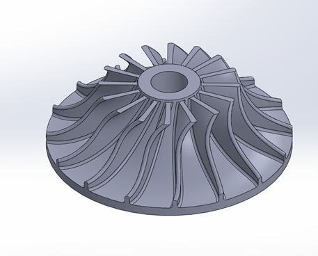
In this current work, the simulation of the axial compressor (semi-open impeller) was carried out using SOLIDWORKS 2016 as shown in Figure 1 with 16 blades. Then the analysis of this compressor was performed using ANSYS 2020 with three different materials (Stainless Steel, Titanium, Carbon Fiber) and mesh generated as shown in Figure 2.
Figure 1. The simulation of axial compressor
Figure 2. The mesh generation
In order to increase the accuracy of the results, the Convergence test was conducted. Many trials were carried out until a constant value for maximum stress was obtained and the number of the elements was 50334 while the node number was 103865 and the element size was 7.652e-003 m. Figure 3 depicts the convergence test.
Figure 3. Convergence test
The mechanical characteristics of the materials that were used in this work are listed in Table 1. In order to understand the behavior of the axial compressor that was manufactured from these materials under various loads, different forces were selected (5000,10000,15000) and get all possible results such as directional deformation, total deformation, maximum shear stress, maximum stress and maximum strain. Figure 3 shows the applied force on the axial compressor.
Table 1. Mechanical properties of materials
|
Materials |
Density Kg/m3 |
Young Modulus (GPa) |
Poisson Ratio |
|
Stainless Steel |
7750 |
193 |
0.31 |
|
Titanium |
4620 |
96 |
0.36 |
|
Carbon Fiber |
1480 |
91.8 |
0.2 |
The design parameters which was used to simulate the axial compressor in this work are listed in Table 2.
Table 2. Design parameters for the axial compressor
|
Parameter |
Value |
|
The outer diameter of the compressor |
125 mm |
|
Compressor width |
5 mm |
|
Compressor hub diameter |
20 mm |
|
Number of blades |
16 |
|
Angle of blade |
8o |
The boundary conditions were applied in ANSYS and applying direct forces perpendicular on the compressor face which is presented in red arrow as shown in Figure 4.
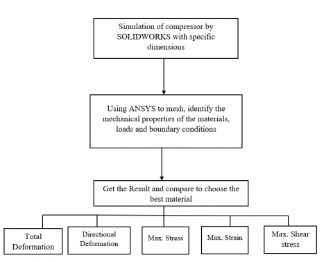
Figure 5 illustrates the block diagram of achieving this study by numerical analysis to understand the best material behavior under loads to avoid failure of the compressor.
Figure 4. Applied force on the axial compressor
Figure 5. Block diagram of the numerical analysis process
The findings of this current study contained the compressor blades which fabricated from various materials (stainless steel, titanium, carbon fiber) and subjected to three different forces (5000, 10000, 15000) N to contrast their behavior and to get the results of directional deformation, total deformation, highest shear stress, highest strain and highest stress as listed in Tables 3, 4 and 5 respectively.
Figure 6 shows the overall deformational for axial compressor blades subjected to a force of 5000 N for carbon fiber material. It is observed that the maximum value for the deformation occurred at the outer edge of the axial compressor and its value decrease slightly towards the hub of the compressor.
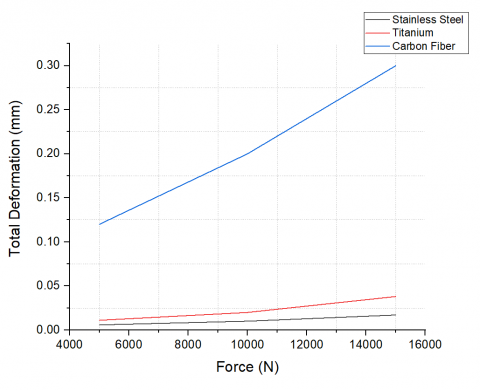
The contrast between the deformation of the materials subjected to the three forces is seen in Figure 7. It was possible to see that the carbon fiber experienced the most overall deformation, measuring 0.3 mm at 15000 N, while the stainless steel experienced the lowest overall deformation, measuring 0.017 mm at 5000 N.This is due to the elements inside the stainless steel which increased its strength against loads while the carbon fiber has shown higher deformation because of its internal failure such as delamination. Moreover, the mechanical properties have a significant effect on the failure of the material because of the strength and Young modulus of carbon fiber is less than the strength of stainless steel and titanium and this caused to produce more deformation in carbon fiber than the other two materials. This high deformation may be caused catastrophic failure to the axial compressor under high loads.
Figure 6. Carbon fiber total deformation
Figure 7. Total deformation
Figures 8, 9 and 10 respectively depict the directional deformation for the materials under force of 5000 N. Figure 11 depicts the directional deformation for carbon fiber under 15000 N.
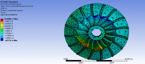
Figure 8. Stainless steel directional deformation under 5000 N
Figure 9. Directional deformation for Carbon fiber under 5000 N
Figure 10. Directional deformation for Titanium under 5000 N
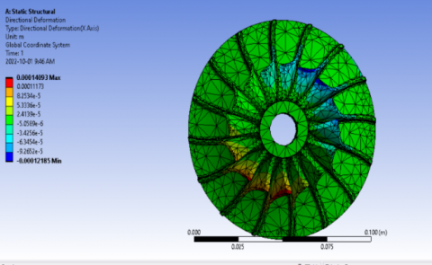
Figure 11. Directional deformation for Carbon fiber under 15000 N
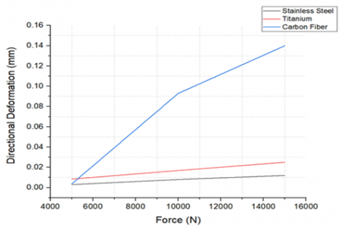
The comparison of the materials' directional deformation is shown in Figure 12. The greatest directional deformation for carbon fiber was 0.14 mm, and the minimum value for both stainless steel was 0.0058 mm. Because of abrupt failure at high loads with various failure mechanisms such as delamination, matrix crack, and fiber/matrix splitting, carbon fiber experienced the most deformation overall.
Figure 13 presents the stress contour for Titanium under 15000 N. It shows the highest magnitude of the stress on the blades and decreases at the outer edge of the compressor.
Figure 12. Directional deformation
Figure 13. Maximum stress for titanium under 15000 N
Table 3. The findings under 5000 N
|
Materials |
Total Deformation (mm) |
Directional Deformation(mm) |
Maximum Strain (mm/mm) |
Maximum Stress (MPa) |
Maximum Shear Stress (MPa) |
|
Stainless Steel |
0.0058 |
0.003 |
0.1 |
20 |
5.01 |
|
Titanium |
0.011 |
0.0084 |
0.2 |
19.5 |
4.7 |
|
Carbon Fiber |
0.12 |
0.0037 |
0.3 |
20.01 |
5.37 |
Table 4. The findings under 10000 N
|
Materials |
Total Deformation (mm) |
Directional Deformation(mm) |
Maximum Strain (mm/mm) |
Maximum Stress (MPa) |
Maximum Shear Stress (MPa) |
|
Stainless Steel |
0.01 |
0.008 |
0.2 |
40.14 |
10 |
|
Titanium |
0.02 |
0.0169 |
0.4 |
39.06 |
9.5 |
|
Carbon Fiber |
0.2 |
0.093 |
0.5 |
30 |
9.47 |
Table 5. The findings under 15000 N
|
Materials |
Total Deformation (mm) |
Directional Deformation(mm) |
Maximum Strain (mm/mm) |
Maximum Stress (MPa) |
Maximum Shear Stress (MPa) |
|
Stainless Steel |
0.017 |
0.012 |
0.3 |
60.02 |
15.5 |
|
Titanium |
0.038 |
0.025 |
0.6 |
58.6 |
14.6 |
|
Carbon Fiber |
0.3 |
0.14 |
0.8 |
39.4 |
14.2 |
The three materials' maximum strains under varying loads are shown in Figure 14. Whereas the minimal value for stainless steel was 0.1 mm/mm under 5000 N, the highest strain was in carbon fiber and it was 0.8 mm/mm under 15000 N. The graph shows that under loads, the strain grew linearly for titanium and stainless steel, but semi-linearly for carbon fiber, which caused the carbon fiber to deform more than the other two materials.
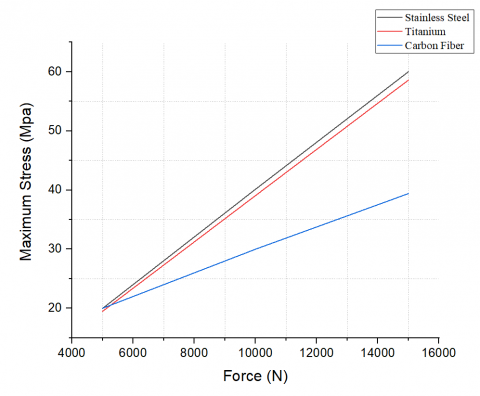
The maximum stress (von Mises) for each of the three materials is shown in Figure 15. Stainless steel at 15000 N experienced a maximum stress of 60.02 MPa, while titanium under 2000 N saw a minimum stress of 19.5 MPa. It could be observed the relationship is linear and direct proportion to the loads and it is noticed that stainless steel could afford more stress which makes it more desirable in the manufacturing process of the axial compressor and moreover it is more resistant to corrosion conditions. Carbon fiber showed less stress and this is due to failure with different modes that prevented carbon fiber to sustain more stress because it had less strength and mechanical properties than stainless steel and titanium and this is important to take into consideration during the manufacturing of compressors from composite materials such as carbon fiber.
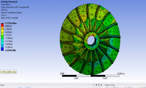
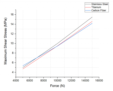
Figure 16 presents the shear stress for carbon fiber under 15000 N and the maximum magnitude was near the impeller hub.
The highest shear stress for each of the materials is shown in Figure 17. Highest shear stress for stainless steel under 15000 N was 15.5 MPa, whereas the lowest result for titanium under 5000 N was 4.7 MPa.
Figure 14. Highest strain for the three materials
Figure 15. Stress for the three different materials
Figure 16. shear stress for carbon fiber under 15000 N
Figure 17. Shear Stress for the three materials
This paper investigated numerically the behavior of the axial compressor for different materials under various loads. ANSYS 2020 was used for the finite element analysis, whereas SOLIDWORKS 2016 was used for the simulation. The outcome demonstrated that the highest total deformation for carbon fiber under 15000 N was 0.3 mm, the maximum stress for stainless steel was 60.02 MPa, and the maximum strain for carbon fiber under 15000 N was 0.8 mm. It is preferred to use stainless steel in the fabrication of axil compressors because it showed less deformation and being more resistant against loads. Although carbon fiber has good characteristics such as being lightweight, it may fail suddenly with different modes such as delamination or cracking which led to catastrophic damage to the engine or other mechanical equipment. For future works, it is advised to use modern materials with various designs of axial and under fatigue and creep loads to investigate the behavior of compressors with these tests.
[1] Boyce, M. (2001). Gas Turbine Handbook. 2nd Edition, Gulf Professional Publishing, Houston.
[2] Mostefa, B., Kaddour, R., Embarek, D., Amar, K. (2021). Analysis and optimization of the performances of the centrifugal compressor using the CFD. International Journal of Heat and Technology, 39(1): 107-120. https://doi.org/10.18280/ijht.390111
[3] Mojaddam, M., Pullen, K.R. (2019). Optimization of a centrifugal compressor using the design of experiment technique. Applied Sciences, 9(2): 291. https://doi.org/10.3390/app9020291
[4] Bardelli, M., Cravero, C., Marini, M., Marsano, D., Milingi, O. (2019). Numerical investigation of impeller-vaned diffuser interaction in a centrifugal compressor. Applied Sciences, 9(8): 1619. https://doi.org/10.3390/app9081619
[5] Xu, C., Amano, R.S. (2008). Computational analysis of swept compressor rotor blades. International Journal for Computational Methods in Engineering Science and Mechanics, 9(6): 374-382. https://doi.org/10.1080/15502280802365840
[6] Gonzalez, J., Fernandez, J., Blanco, E., Santolaria, C. (2002). Numerical simulation of dynamic effects due to impeller-volute interaction in a centrifugal pump. Journal of Fluids Engineering, 124(2): 348-355. https://doi.org/10.1115/1.1457452
[7] Chima, R.V. (2006). A three-dimensional unsteady CFD model of compressor stability. ASME Turbo Expo 2006, 6: 1157-1168. https://doi.org/10.1115/GT2006-90040
[8] Xu, C., Amano, R.S. (2017). Centrifugal compressor performance improvements through impeller splitter location. Journal of Energy Resources Technology, 140(5): 051201. https://doi.org/10.1115/1.4037813
[9] Denton, J.D., Dawes, W.N. (1998). Computational fluid dynamics for turbomachinery design. Journal of Mechanical Engineering Science, 213(2): 107-124. https://doi.org/10.1243/0954406991522211
[10] Xu, C., Amano, R.S. (2017). Effects of asymmetric radial clearance on performance of a centrifugal compressor. Journal of Energy Resources Technology, 140(5): 051201. https://doi.org/10.1115/1.4038387
[11] Dickmann, H.P., Wimmel, T.S., Szwedowicz, J., Filsinger, D., Roduner, C.H. (2006). Unsteady flow in a turbocharger centrifugal compressor, three-dimensional computational fluid dynamics simulation and numerical and experimental analysis of impeller blade vibration. Journal of Turbomachinery, 128(3): 455-465. https://doi.org/10.1115/1.2183317
[12] Xu, C., Amano, R.S. (2012). Aerodynamic and structure considerations in centrifugal compressor design-blade lean effects. Turbo Expo, pp. 557-568. https://doi.org/10.1115/GT2012-68207
[13] Rao, B.J., Rajesh, K., Reddy, P.K., Rushikesh, G., Anil, P. (2021). Design and analysis of axial flow compressor using different materials. Bulletin Monumental, 22(7). https://doi.org/10.37896/BMJ22.7/4018
[14] Lakshmi, P, Raju, B.B., (2017). Design modification and FEA analysis of axial flow compressor. International Journal of Innovative Technology and Research. 5(4): 7064-7070.
[15] Aziaka, D.S., Osigwe, E.O., Lebele-Alawa, B.T. (2014). Structural and conceptual design analysis of an axial compressor for a 100 MW industrial gas turbine (IND100). World Journal of Mechanics, 4(11): 332. http://dx.doi.org/10.4236/wjm.2014.411033
[16] Srinivas, K., Deepthi, K., Rao, K.N.D.M. (2014). Design and optimization of axial flow compressor. International Journal of Computational Engineering Research (IJCER), 4(10): 2250-3005.
[17] Jebieshia, T.R., Raman, S.K., Kim, H.D. (2019). Aerodynamic and structural characteristics of a centrifugal compressor impeller. Applied Sciences, 9(16): 3416. https://doi.org/10.3390/app9163416
[18] Schneider, A., Will, B.C., Böhle, M. (2013). Numerical evaluation of deformation and stress in impellers of multistage pumps by means of fluid structure interaction. In Proceedings of the ASME 2013 Fluids Engineering Division Summer Meeting, Incline Village, NV, USA, pp. 1-10.
[19] Zhao, H., Deng, Q., Zheng, K., Zhang, H., Feng, Z. (2014). Numerical investigation on the flow characteristics of a supercritical CO2 centrifugal compressor. In Proceedings of the ASME Turbo, pp. 1-10. https://doi.org/10.1115/GT2014-26646
[20] Piperno, S., Farhat, C., Larrouturou, B. (1995). Partitioned procedures for the transient solution of coupled aroelastic problems Part I: Model problem, theory and two-dimensional application. Computer Methods in Applied Mechanics and Engineering, 124: 79-112. https://doi.org/10.1016/0045-7825(95)92707-9
[21] Kang, H.S., Kim, Y.J. (2016). A study on the multi-objective optimization of impeller for high-power centrifugal compressor. International Journal of Fluid Machinery and Systems, 9(2): 143-149. https://doi.org/10.5293/IJFMS.2016.9.2.143