Ali Sabri Abbas | Ayad Ali Mohammed*
© 2022 IIETA. This article is published by IIETA and is licensed under the CC BY 4.0 license (http://creativecommons.org/licenses/by/4.0/).
OPEN ACCESS
A plate fin heat exchanger PFHE is a form of compact heat exchanger CHE containing of a block of alternating layers of fins and flat separators known as parting sheets. In this paper, 3-dimensional incompressible laminar flow and heat transfer in a (PFHE) has been investigated numerically. The influences using different fin configurations and the effect of the offset of these fins, on thermal and hydro-dynamic fields are presented. The cases of study for the PFHE are established, by using the fins with different configurations (plain rectangular (PR) and it's offset (OR), plain triangular (PT) and it's offset (OT) which is a novel shape, and a novel combination of a two fin shapes, between rectangular and triangular (ORT)). The upper and lower plates are exposed to a constant heat flux and the working fluid is air where chosen under a laminar range of (Re) number (600 to 1400). The laminar flow and heat transfer is governed by continuity, momentum and energy equations. ANSYS FLUENT (2021 R1) is used to get the numerical results, based on finite volume method. One of the most utilized fins for a PFHE is the offset fin arrangement due to its higher heat change amount, adjustable structure, and enhances flow turbulence and heat transfer coefficient by interrupting the thermal boundary layer. The obtained results of using of the offset configuration increases the Nusselt number by 20.32% and 17.82% for OSF rectangular and OSF triangular, respectively as compared with the with plain configurations, as a result, a significant heat transfer enhancement is observed. And significant increase in the friction-factor is found to be 79.8% and 48.7% for OT and ORT, as compared with the PT. It can be observed that use of the OSF configuration leads to greater f-factor for triangular configuration values. In addition, the temperature fields for the primary and secondary flows were showed in a contour diagram.
plate fin, fin heat, exchanger, configurations, flow, performance, enhancement, friction
Fins are surface augmentations that are frequently employed in different types of heat exchangers to increase the efficiency of heat transfer between a solid surface and nearby fluid. The heat exchanger's surface area density was occasionally raised by combining geometrically better fins, which also helped to develop the convection heat transfer factor. These increased surface compact cores have several instances like OSF, Louvered fins, Wavy fins, Plain fins, and Pin fins [1]. Plate fins, pin fins, offset strip fins, louvered fins, and wavy fins are some of the different types of finned surfaces that are used in plate fin type of dense heat exchangers, where the finned surfaces actually offer a huge surface area density. These finned surfaces are used in several automotive, refrigeration, and air conditioning, propulsion system, waste heat recovery, cryogenic, and other heat recuperative uses. The fin geometry made the implementation of a (PFHE) unnatural as well [2]. The most prevalent fin configurations were interrupted fins and simple fins with rectangular, trapezoidal, or triangular channels. The investigation of "laminar and turbulent" flow and fluid dynamics in OSF fin designs has attracted a lot of research attention. Numerous scholars have investigated the features of fluid flow and heat transmission both numerically and experimentally.
Plain Fins:
Simple fins were continuous and in a line. The cross-sections of plain fins were typically triangular and rectangular. Compared to other designs of fins, the manufacture of triangular fins was straightforward. The plain fins, on the other hand, had weak structural integrity and limited heat transmission during laminar flow. Plain fins were typically utilized for pressure dips that could be harmful [3].
In order to evaluate the heat transfer factor (j) and the heat exchanger core pressure drop characteristic f-factor as functions of the heat exchanger geometry and Re number, Bose et al. (2019) presented a comprehensive mathematical research of the rectangular (PFHE). They examined the execution of the plain rectangular model using the finite volume approach (PFHE). They came to the conclusion that the (f) and (j) factors differ nonlinearly inside the boundaries of fin geometry, which are (1 h/s 4) and (0.04 t/s 0.14), and the laminar area of 200 Re 800. Additionally, they saw that (f) and (j) both decreased as Re and (t/s) increased, but increased with h/s [4].
The heat transfer correlations for rectangular plain fins were published by Bala et al. in 2013. The "heat transfer coefficient" could be calculated for all Re number magnitudes, including laminar and turbulent zones, using the formulas provided in terms of j-factor and f-factor. On the flat plate channel, there were installed rectangular fins. By comparing the correlations for the (f) and (j), it had been determined that they were accurate. For a compacted plate type HE, the parameters for heat transmission and friction-coefficient are presented, and they are in excellent agreement with the experimental data [5].
The heat transmission and f-factor correlations for plate-fin compact HE's triangular plain fin surfaces were presented by Bala et al. in 2015. The fluent software application was used to finish the numerical calculations. For a range of Re numbers, the coefficients (j) and (f) were calculated. These magnitudes were compared to the (j) and (f) coefficient data from previous, relevant investigations. Two different equations covering the low and high Re areas, as well as geometrical dimensionless elements, had been used to express the correlations [6].
By using the program COMSOL 4.3, Jia and Hu [7] created a numerical model to simulate a counter flows parallel HE. On the flat plate channel, there were installed rectangular fins. To replicate the heat transfer and fluid flow pattern in a unit cell of one cold channel and one hot channel, the researchers' study built a three-dimensional model of a multilayered counter flow parallel heat exchanger. Water and oil are both functioning fluids. The optimum HE design can be guided by the precise temperature, velocity, and pressure distributions in the channels.
Offset Strip Fins (OSF):
One of the greatest parts for improving heat transfer in airplanes, cryogenics, and other industrial processes that don't require mass production is OSF. The highest heat transfer performance surfaces are OSF surfaces. This was accomplished by reattaching the new, thin boundary layer to the fin plate of each (OSF) fin module and periodically disturbing it. Their heat transmission efficiency was 1.5 to 4 times greater than that of simple fins. If the study's focus had been on analyzing the pressure drop and heat transfer typical of (PFHE), concentrating on the (OSF) kind of (PFHE) [8].
Tiwari et al. [9] used the calculating approach of fluent simulation software to assess the performance factors of a counter flow HE. The results show that efficiency increased with mass flow rate, and both the theoretical and actual total heat transfer factors rise as mass flow rate increases. The overall thermal conductance increased as the j-factor grew, which was proportional to the heat transfer factor. Finally, they came to the conclusion that the pressure drop swiftly grew because the pressure drop in the HE varies with the shifting mass flow rate. There were numerous deviations.
By using numerical analysis, Bhowmik and Lee [10] investigated a steady-state three-dimensional mathematical model to assess the heat transmission and pressure drop properties of an OSF-HE. The (fcor) and (jcor) factors could be used to investigate flow and heat transfer in laminar, turbulent, and even transitional zones thanks to a common correlation known as the derivative. Using the correlated jcor, the effect of Prandtl numbers was determined and the Nusselt number was projected. For various fluids, three alternative performance criteria for HEs were evaluated.
Yang and Li [11] employed numerical analysis to examine the heat transmission and flow f-factors for offset strip fins (OSF) used in (PFHE)s. Comprehensive analysis of the geometrical effects on the thermal hydraulic performance s for OSF fins was conducted. According to the findings of the experimental research, the proposed correlation may be calculated using 92.5% of the (j) data and 90.3% of the (f) data within 20%, with RMS errors under 15%. Comparing the suggested correspondences to the existing ones reveals that they provide calculations for OSF fins of various thicknesses covering a wide range of blockage ratios, whereas the earlier correspondences only adjust for the thinner fins and actually depart from practice at higher blockage ratios [11].
Plain and Offset Strip Fins:
Yang et al. [12] looked at the conformist fin's qualities, including efficacy and efficiency. They employed an offset strip fin (OSF) and a plain fin, which was mathematically, examined using 3D models with strong validation. The analysis's findings demonstrated that the thermal performance of the fin surface increased with actual fin efficiency. In areas with relatively low Re, the OSF fin's fin performance was higher than the plain fin's with the same cross section, however plain fins perform better in areas with Re > 1000. Additionally, the OSF fins with big (d) were well chosen in the low Re zone, whilst those with small (d) are better suited for use in conditions with a relatively high Re number.
In one-side heated vertical channels with plain fins, serrated fins, and perforated fins, Yang et al. [13] investigated the evaluation of heat transfer and flow friction qualities using experimental and mathematical analysis. The heating situation and Prandtl number influences caused the experimental j-factor of the serrated fin to be equal to 20% less than the values of "Manglik and Bergles" correlation, whereas the friction-coefficient (f) showed a well agreement with the results of "Manglik and Bergles" correlation with a relative error of 10%. This is because the friction-coefficient (f) was primarily influenced by Re number.
Four fundamental (PFHE) fins were computer generated by Zhu and Li [14] using 3-dimensional numerical simulations of the flow and heat transfer in the laminar flow domain. The (PFHE)s, rectangular plain fins, strip offset fins, perforated fins, and wavy fins were all included in the model geometry. The analysis' findings indicate that there was good agreement between the computations and the experimental analysis. Additionally, a data-decreasing method for calculating the local Nusselt numbers, (j) coefficient, and (f) coefficient was provided. Using this method, the properties of the four fins' pressure drop and heat transfer were obtained and thoroughly examined.
Yang et al. [15] evaluated the offset strip fins' improved heat transfer utilizing in (PFHE). To accurately depict the thermodynamic performance of various path architectures, they suggested a method of solution known as a relative entropy generation distribution coefficient (PFHE). A typical offset strip (OSF) and a plain fin model are the model geometries. According to the analysis's findings, the relatively small results in better implementation, while the parameter or, which contribute to the greatest degree of OSF fin heat transfer enhancement, should be computed after the other two geometric parameters have been selected.
The goals of this study can be summarized as investigating how the OSF fin configuration affects heat transfer to a single-phase fluid in PFHE and gaining a better and more quantitative understanding of the heat transfer process that takes place when a fluid passes through the OSF fin configuration as follows:
• Inspect the hydro-dynamics and thermal performance of different fin configuration.
• Analysis the effect of using the OSF fin configuration on flow field, heat transfer enhancement and friction losses.
• Using a novel fin shapes (OT and ORT) and examining them hydrodynamics and thermal performance.
Paper's Layout:
2. Model description: Illustrates the model geometry and the boundary conditions.
3. Demand to capacity ratio results: Explains the numerical method.
4. Results and discussion: Illustrates results and discussion.
5. Conclusions: Provides a set of conclusions drawn from this study.
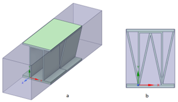
New proposed of various fin shapes and the offset of these fins were studied. The initial dimensions chosen were from the geometry designated as 6.2 [16], including two plain fins (plain rectangular (PR) and plain triangular (PT)), the offset of these fins (offset rectangular (OR) and a novel shape which is offset triangular (OT)), and an another novel one combination of two geometries which is offset rectangular-triangular (ORT), as shown briefly in Figures 3-8, by investigating their thermo hydraulic features by exploring its Nusselt number (Nu) , f-factor (f), J-factor (j) and pressure drop (Δp). For the present study, the new and innovated suggested offset fin geometries are considered to investigate their performance which is the (OT) and (ORT). Five cases of plate fin heat exchanger fin geometers, were created on Workbench 2021, the front view of the computational domain for each case is illustrated in Figures 1-5. The detailed description for fins geometries is illustrated in Table 1.
Air enters the PFHE at various laminar Re numbers (velocities), and the exit is through an outflow boundary. A laminar, isothermal, and steady-state condition will be taken into consideration to solve the flow field. Five Re values, ranging from 600 to 1400, and a fixed Pr number have been covered in the study. Knowing the local heat flux which is 3,000 w/m2, values of local heat transfer coefficients along the upper and lower plates allowed for the calculation.
Figure 1. (a) Plain rectangular fin, (b) Front view of a plain rectangular fin
Figure 2. (a) OSF rectangular fin, (b) Front view of a OSF rectangular fin
Figure 3. (a) Plain triangular fin, (b) Front view of a plain triangular fin
Figure 4. (a) OSF triangular fin, (b) Front view of a OSF triangular fin
Figure 5. (a) OSF rectangular-triangular fin, (b) Front view of OSF rectangular-triangular fin
Table 1. The detailed description for fins geometries
|
Fin shape |
Fin height, h (mm) |
Fin space, s (mm) |
Fin thickness, t (mm) |
Interrupted length, l (mm) |
Hydraulic diameter D (mm) |
|
Case1(PR) 6.2 [15] |
10.25 |
4 |
0.25 |
/ |
5.454 |
|
Case2 (OR) |
10.25 |
4 |
0.25 |
8 |
5.312 |
|
Case3 (PT) |
10.25 |
4 |
0.25 |
/ |
3.08 |
|
Case4 (OT) |
10.25 |
4 |
0.25 |
8 |
3.557 |
|
Case5 (OPT) |
10.25 |
4 |
0.25 |
8 |
3.557 |
3.1 Assumptions
The proposed model solution is simplified on the following presumptions:
(1) Three-dimensional model;
(2) The air is the working fluid;
(3) A constant properties fluid;
(4) Steady state flow;
(5) The flow is incompressible;
(6) The gravity effect is neglected;
(7) Non slip flow is assumed;
(8) The airflow is laminar, and laminar model was used;
(9) Neglecting the dissipation of heat is assumed;
(10) The wall thickness is neglected.
3.2 Governing equations
By resolving the average differential equation of mass (continuity) and momentum equation, the laminar incompressible stable equations may be used to describe the fluid motion in the plate fin heat exchanger for the laminar state:
3.2.1 Continuity equation
The mass conservation is mathematically represented by the continuity equation. Its form is [17]:
$\frac{\partial U}{\partial x}+\frac{\partial V}{\partial y}+\frac{\partial W}{\partial z}=0$ (1)
$\frac{\partial u}{\partial x}+\frac{\partial v}{\partial y}+\frac{\partial w}{\partial z}=0$ (2)
3.2.2 Momentum equations (NSEs)
Equations of momentum are a group of equations that derived throughout Newton second law of momentum to conserve the fluid momentum in the three directions of fluid motion; x, y and z [18]. These equations are known as Navier-Stokes equations (NSE), named after Navier and Stokes [19]:
Momentum equation in x-direction:
$\rho\left(u \frac{\partial u}{\partial x}+v \frac{\partial u}{\partial y}+w \frac{\partial u}{\partial z}\right)=-\frac{\partial p}{\partial x}+\left(\frac{\partial^2 u}{\partial x^2}\right)+\left(\frac{\partial^2 u}{\partial y^2}\right)+\left(\frac{\partial^2 u}{\partial z^2}\right)$ (3)
Momentum equation in y-direction:
$\rho\left(u \frac{\partial v}{\partial x}+v \frac{\partial v}{\partial y}+w \frac{\partial v}{\partial z}\right)=-\frac{\partial p}{\partial x}+\left(\frac{\partial^2 v}{\partial x^2}\right)+\left(\frac{\partial^2 v}{\partial y^2}\right)+\left(\frac{\partial^2 v}{\partial z^2}\right)$ (4)
Momentum equation in z-direction:
$\rho\left(u \frac{\partial w}{\partial x}+v \frac{\partial w}{\partial y}+w \frac{\partial w}{\partial z}\right)=-\frac{\partial p}{\partial x}+\left(\frac{\partial^2 w}{\partial x^2}\right)+\left(\frac{\partial^2 w}{\partial y^2}\right)+\left(\frac{\partial^2 w}{\partial z^2}\right)$ (5)
3.2.3 Energy equation
$u \frac{\partial T}{\partial x}+v \frac{\partial T}{\partial y}+w \frac{\partial T}{\partial z}=\frac{k}{\rho C_p}\left[\frac{\partial^2 T}{\partial x^2}+\frac{\partial^2 T}{\partial y^2}+\frac{\partial^2 T}{\partial z^2}\right]$ (6)
3.3 Boundary conditions
The inlet velocity for air (cold fluid) was uniform with a temperature of 300 k and an outlet pressure equal to zero. Furthermore, the upper and lower plates of the plate fin heat exchanger were kept at a constant heat flux of (q=3,000W/m2). To facilitate simulation, periodic boundary conditions were adopted for the left and right sides of the computational domain. Finally, the velocity at the walls is assumed to be zero (no-slip).
3.4 Hydrodynamic parameters
The required outcomes have been found by using the "Area Weighted Averaged", "wall flux", and "interfaces" in a sequence for calculating Nu, Q, h, Δp.
For pressure drop, since the outlet is set to pressure zero, the pressure drop equal to the pressure at the inlet.
Pin-Pout=ΔP
While volume weighted Averaged, mass, and fluid are used in a sequence to calculate the mean velocity (u) and density ($\rho a v$).
The Reynolds number, which is normally used to describe the flow phenomena depend on the four quantities: The diameter of the flow and the viscosity, density, and average liner velocity of the fluid. The Reynolds number is defined by equation [20]:
Re=inertial forces/viscous forces
$\mathbf{{R e}=\rho U_{i n} D_h / \mu}$ (7)
where, Dh is the hydraulic diameter which is One of the important parameters which characterizing the flow in ducts or tubes is the hydraulic diameter. This is used with fluid properties and Reynolds number to calculate inlet velocity [21].
$D_h=\frac{4 A_c}{P_{e r}}=\frac{4 A_c L}{A}$ (8)
where, L is the total length of the plate-fin channel, A is the total heat transfer area, and Ac is the free flow area in the cross section.
The Nusselt number on the heated tube is defined as [12]:
$\mathrm{Nu}=\frac{1}{A_{(x, z)}} \int_0^l \int_0^w N u d z d x$ (9)
$N u=\frac{h D_h}{k}$ (10)
where, h is the actual average gas-side heat transfer coefficient.
The definition of the friction coefficient in terms of shear stress at the channel surface as:
$\mathrm{C}_{\mathrm{f}}=\tau_{\mathrm{w}} / \frac{1}{2} \rho \mathrm{U}^2$ (11)
where, τw is the wall is shear stress and defined as [22]:
$\tau_{\mathrm{w}}=\mu \sqrt{\left(\frac{\partial \mathrm{u}}{\partial \mathrm{y}}\right)^2+\left(\frac{\partial \mathrm{w}}{\partial \mathrm{y}}\right)^2}$ (12)
Additionally, the friction factor (Fanning fraction factor) is provided by [12]:
$c_f=\frac{f}{4}$ (13)
A dimensionless term, the Colburn (j) factor is a function of the Pr number and the Re number. It is crucial for figuring out the fluid's heat transfer coefficient. The source of the J-factor is [12]:
$\mathrm{j}=\mathbf{S t} \operatorname{Pr}^{2 / 3}=\frac{\mathrm{h}}{\rho \mathrm{uC}_p} \operatorname{Pr}^{2 / 3}$ (14)
Additionally, this component aids in the different correlations which are researchers have built to assess the fluid flow parameters, where St is the Stanton number.
3.5 Grid independency
In order to select the optimal grid and obtain a better solution, a grid independence study is prepared. The investigation of grid independence is taken into account in the current results seven different values. Table 2 provides a summary of the specified grid for all shapes. At Re=600, the f-factor is calculated for each arrangement. It is discovered that the value of the f-factor has barely changed. The grid resolution examination exposes that at the cells 249670, 171214, 151214, 182214 and 186213 cells respectively, the PR, PT, OR, OT and ORT become independent of the grid.
Table 2. Different studied cases and them different grids with their f-factor results
|
No. |
Case |
No. of grid elements |
f |
fdeviation |
|
1 |
PR |
62586 |
0.122821744 |
0.007750615 |
|
92739 |
0.1218698 |
0.005076959 |
||
|
142785 |
0.121251072 |
0.004802201 |
||
|
249670 |
0.1206688 |
0.010445915 |
||
|
517618 |
0.119408304 |
0.066031455 |
||
|
758934 |
0.1115236 |
0.083408713 |
||
|
1299958 |
0.10222156 |
|
||
|
2 |
PT |
40120 |
0.621241 |
0.004730853 |
|
56010 |
0.618302 |
0.002427778 |
||
|
66986 |
0.6168009 |
0.00407895 |
||
|
107657 |
0.614285 |
0.00082421 |
||
|
171214 |
0.6137787 |
0.001583959 |
||
|
270681 |
0.6128065 |
0.003961773 |
||
|
634526 |
0.6103787 |
0.003534855 |
||
|
3 |
OR |
46010 |
0.118302 |
0.012688205 |
|
66986 |
0.11680096 |
0.021539823 |
||
|
97657 |
0.114285088 |
0.004430709 |
||
|
151214 |
0.113778724 |
0.008544198 |
||
|
260681 |
0.112806576 |
0.021522008 |
||
|
524526 |
0.110378752 |
0.019535028 |
||
|
751330 |
0.1082225 |
|
||
|
4 |
OT |
61010 |
0.137822732 |
0.15222261 |
|
72986 |
0.116842996 |
0.078698051 |
||
|
111657 |
0.10764768 |
0.020153151 |
||
|
182214 |
0.10547824 |
0.214942343 |
||
|
281681 |
0.0828065 |
0.270845888 |
||
|
682526 |
0.0603787 |
0.201355776 |
||
|
9201330 |
0.0482211 |
|
||
|
5 |
ORT |
65012 |
0.119822731 |
0.058251 |
|
82986 |
0.112842995 |
0.072626 |
||
|
113658 |
0.10464768 |
0.020731 |
||
|
186213 |
0.10247824 |
0.094378 |
||
|
292682 |
0.0928065 |
0.133911 |
||
|
622526 |
0.0803787 |
0.151254 |
||
|
1211330 |
0.0682211 |
|
3.6 Solving by FLUENT
The commercial (CFD) code can be used to solve the numerical method of the discredited governing equations. Ansys Fluent 2021 R1 is the program uses to calculate the current numerical investigation. Fluent is frequently used in this field and it is regarded as some of the best code currently in use [23]. The governing equations are approximated using a laminar model and finite volume discretization. The numerical computation employs a pressure-based solver with double precision. On the PFHE surface, a non-slip boundary condition is used. For pressure velocity coupling, the SIMPLE method is employed. The discretization of all terms was done using a second order upwind approach.
3.7 Validations
Through this work the f-factor values for the OSF fin in the PFHE is established numerically, for the experimental works of [13]. The validations include the f-factor is displayed in Figure 6.
Figure 6. Comparison of the numerical values and the experimental data of f-factor f air tests for [13]
The average deviation for f-factor between the experimental works [13] and the numerical work is 3% which shows a good agreement.
The numerical results in this section, has been addressed to verify the strengthening of forced convection in a PFHE with different fin configuration. For the PR, OR, PT, OT, and ORT, respectively, the hydraulic-diameter of the fins domain is (0.005454m), (0.0053126m), (0.00308m), (0.003557m), and (0.00444m). The studied cases for PFHE of different plain shapes with respect to the OSF of these shapes are discussed.
4.1 Nusselt number
Figure 7 shows how the fin geometry affects the average Nu number variation for various laminar Reynolds range values. For all taken values of Reynolds number, it is believed that the Nu number of the OSF fin is higher than that of the plain fin. However, for high Reynolds numbers (Re=1000 to 1400), this rise appears to be greater. Comparing the (OT) to other geometries, the Nu number growth was the greatest. The results showed that, when compared to plain configurations, the OSF rectangular and the OSF triangular showed an enhancement in the mean Nu of 20.32% and 17.82%, respectively. However, for the rectangular shape, this enhancement was reduced as the Reynolds number increased, and for the triangular shape, the enhancement in heat transfer was significantly increased as the Reynolds number increased. It is observed from the figure that there is a significant decrease in heat transfer by 13.7 of the ORT as compared with PT which was caused by using different offset geometries. It should be noted that using the OSF configuration results in greater heat transfer for all the plain fin values taken into consideration. This is due to the secondary flow formation and flow separation that occur at the OSF section, which leads to better disorganized mixing between the central and wall areas. This flow mixing disturbs the boundary layer and as a result intensification the heat transfers.
Figure 7. Effect of fin geometry on Nusselt number in a laminar Reynold range
4.2 Friction factor
The effect of the fin geometry on the average f-factor variation for various Reynolds number values is shown in Figire 8. It is obvious that when the Reynolds number increases, the f-factor obtained from all fin geometries decreases. The figure shows that the f-factor for using OR and PT has significantly decreased, whereas the f-factor for OSF, especially OT, has significantly increased. The obtained data showed that, when comparing OT and ORT to PT, the f-factor increased by 79.8% and 48.7%, respectively. It can be seen that using the OSF configuration results in values for the triangular configuration having a higher f-factor. The flow resistance rises as a result of form drag on the leading edges of the fin sections facing the flow and as a result of trailing edge vortices. This is caused by the wall shear stress at the serrated section.
Figure 8. Effect of fin geometry on F-factor in a laminar Reynold range
4.3 Pressure loss
Figure 9 illustrates how the fin geometry affects the pressure-drop variation for various laminar values of Re number. It is clear that as Re number increases, the pressure losses resulting from the use of all fin shapes get larger. Compared to other fin geometries, the OSF triangular fin indicated the highest growth in pressure drop. The gathered data showed that, when compared to plain fins, the pressure loss increased by 9.8% and 10.5% for rectangular and triangular OSF, respectively. Compared to plain fins, the rise in pressure loss with an OSF arrangement is significantly greater. This is because the fluid's dynamic pressure is dispersed due to the increase in f-factor which is produces a reverse flow.
Figure 9. Effect of fin geometry on pressure drop in a laminar Reynold range
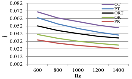
4.4 Colburn factor
Figure 10 illustrates how the fin geometry affects the average J-factor variation for various Reynolds number values. Since J-factor is a function of the heat transfer coefficient of the flowing fluid, the heat transfer performance is represented by the Colburn factor. It can be seen that as the Reynolds number increases, the J-factor created by all fin geometries decreases in a nonlinear manner. For all the studied values of Reynolds number, it is seen that the J-factor of the OSF fin is higher than that of the plain fin. Comparing the (OT) to other geometries, the J-factor increase was shown to be the greatest.
Figure 10. Effect of fin geometry on Colbern factor in a laminar Reynold range
4.5 Thermal characteristic
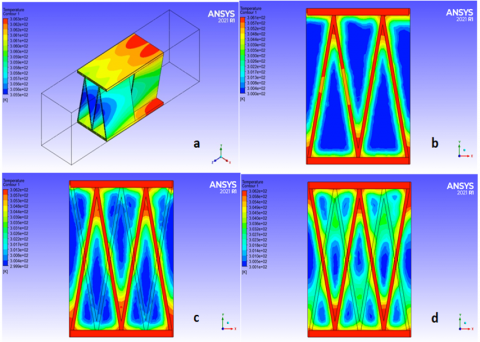
The heat exchanger bundle's global temperature contours explain the heat transfer. The fin material's thermal conductivity impacts temperature distribution [24]. This section deals with the temperature variation along the domain, a temperature contour has been captured as shown in Figures 11 -15, the frame b, c and d illustrate the section of the domain at l=4 mm, l=8 mm and l=12 mm, where the outlet temperature of the domain increases with respect to the flowing downstream for all fin geometries. This variation in temperature distribution was displayed for the case of PFHE and the effect of the fin geometry variation, for air flowing with Re=600. In the present study, the fin was utilized with a small thickness which is equal to 0.25 mm; where has been noticed that transverse temperature changes inside the fin are minimal compared to fin longitudinal temperature differential.
In each case, the cold flow (air) passes across the fin in the domain and absorbs heat from the finned plates through the heat transfer process, which leads to a reduction in the internal cold area in the fluid domain as well as the flow flows more downstream, as represented by the dark blue fluid color entering the domain, which turns to light blue after crossing the fins. Thus, outlet air temperatures are higher than inlet. Furthermore, the outline of the cold fluid stream (air) is the region where the fluid turns light blue due to heat gained from contact with the finned plate, whereas the middle of the stream remains dark blue until the end of the fin length. As shown in temperature distributions figures, the fin's base temperature is high and decreases towards the channel center.
The fin material should have high thermal conductivity to reduce temperature changes. In the case of infinite thermal conductivity, the whole fin would be at the base surface's temperature, maximizing heat transmission. A fin's finite conduction resistance requires a temperature differential along the fin. OSF fin provide more heat transfer surface per plate length than a plain fins. In agreement with [11-13], OSF fins' cut design leads to the breakdown of the boundary layer in a frequent manner and improved flow penetration to the fin root, resulting in increased heat transfer coefficients.
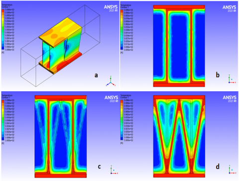
For (OR), as shown in Figures 12, the blue area that is refers to the cold temperature where reduced as the flow going downstream more than PR, due to rising in heat attracted by the fluid from the fin wall and the growing of thermal boundary layer, and due to the OSF geometry which is increases the heat transfer generation between the fins and the fluid domain. As it's shown from the figures below, as the blue area reduced as well as the heat transfer enhanced between the fins and the flowing fluid, so it's clear form these figures that the OT is the better fin geometry in the heat enhancement than the others, and the PT fin in the second place, which is agreed with the Figure 7 results.
Figure 11. Temperature distribution for plain rectangular fin for Re=600. (a) fluid domain in contact with the fin, (b) section of the domain at l=4 mm, (c) section of the domain at l=8 mm, (d) section of the domain at l=12 mm
Figure 12. Temperature distribution for OSF rectangular fin for Re=600. (a) fluid domain in contact with the fin, (b) section of the domain at l=4 mm, (c) section of the domain at l=8 mm, (d) section of the domain at l=12 mm
Figure 13. Temperature distribution for plain triangular fin for Re=600. (a) fluid domain in contact with the fin, (b) section of the domain at l=4 mm, (c) section of the domain at l=8 mm, (d) section of the domain at l=12 mm
Figure 14. Temperature distribution for OSF triangular fin for Re=600. (a) fluid domain in contact with the fin, (b) section of the domain at l=4 mm, (c) section of the domain at l=8 mm, (d) section of the domain at l=12 mm
Figure 15. Temperature distribution for ORT fin for Re=600. (a) fluid domain in contact with the fin, (b) section of the domain at l=4 mm, (c) section of the domain at l=8 mm, (d) section of the domain at l=12 mm
This study explored numerically the heat transfer Nusselt number, f-factor, and pressure drop of various configuration fins in aluminum air plate-fin heat exchangers (PFHE). A thorough explanation of the fins' local and average heat transfer properties, including temperature distribution and J-factor, was also provided and debated.
(1) A numerical thermo-fluid-dynamic model is established in this paper, which can predict the flow and heat transfer characteristics at laminar Reynolds number.
(2) By using OSF fin configuration, the heat transfer in the PFHE could be improved highly.
(3) The employment of the OSF fin shape offers superior heat transfer than that of the plain rectangular and triangular configurations.
(4) Over a range of studied laminar Re numbers, OT shape displays higher Nusselt number while PT yielded best f-factor in contrast with the other fin geometries.
(5) In the PFHEs, the f-factor is temperature independent.
(6) In this paper, a good agreement was accomplished between the experimental data of Yang et al. [12] and numerical predictions for the j-factor.
(7) The augmentation in the mean Nusselt is found to decline as increasing the Reynold number for the rectangular shape, and vice versa for the triangular shape there is a significant increase in the heat transfer enhancement as increasing Re number.
(8) The rectangular fins configuration shows the slightest pressure drop than the triangular fins.
(9) Using the combination of two the geometries (ORT) produces enhance in heat transfer than rectangular shape and enhance in f-factor than triangular shape.
(10) It seen that the OT fin has a higher pressure drop and heat transfer among all calculated cases while the PR fin shows the poorer performance among the same cases.
[1] Incropera, F.P. (1999). Liquid Cooling Electronic Devices by Single-Phase Convection. John Wiley & Sons, New York.
[2] Holman, J.P. (2002). Heat Transfer. 9th Edition, McGraw-Hill, New York.
[3] Nabil, R., Sabri, A. (2022). A review on the modification of circular fin and tube heat exchangers through new innovative fin shapes. International Journal of Advanced Technology and Engineering Exploration, 9(93): 1122-1245. https://doi.org/10.19101/IJATEE.2021.875888
[4] Bose, A., Shekhar, C., Adnan, M. (2019). Thermo-hydraulic performance analysis of plain rectangular plate fin heat exchangers in laminar region-a numerical study. Int. J. Adv. Sci. Eng., 6(S1): 25-29. https://doi.org/10.29294/IJASE.6.S1.2019.25-29
[5] Bala Sundar Rao, R., Ranganath, G., Ranganayakulu, C. (2013). Development of colburn ‘j’ factor and fanning friction factor ‘f’ correlations for compact heat exchanger plain fins by using CFD. Heat Mass Transfer 49: 991-1000. https://doi.org/10.1007/s00231-013-1140-0
[6] Bala Sundar Rao, R., Ranganath, G., Ranganayakulu, C. (2015). Colburn ‘j’ factor and fanning friction factor ‘f’ correlations of triangular plain fin surface of a compact heat exchanger using CFD. In Applied Mechanics and Materials, pp. 207-211. https://doi.org/10.4028/www.scientific.net/AMM.787.207
[7] Jia, R., Hu, J. (2014). Analysis of a counter flow parallel-plate heat exchanger. ASEE 2014 Zone I Conference, University of Bridgeport, Bridgeport, CT, USA.
[8] Dewatwal, J. (2009). Design of compact plate fin heat echanger. Master of Science Thesis, The graduate of Indian Institute of Technology, Kharagpur.
[9] Tiwari, A., Raja, R., Kumar, R. (2018). Performance studies on plate fin heat exchanger with CFD simulation. International Journal of Engineering and Innovative Technology, 8(1): 40-45. https://doi.org/10.17605/OSF.IO/FK3WN
[10] Bhowmik, H., Lee, K.S. (2009). Analysis of heat transfer and pressure drop characteristics in an offset strip fin heat exchanger. International Communications in Heat and Mass Transfer, 36(3): 259-263. https://doi.org/10.1016/j.icheatmasstransfer.2008.11.001
[11] Yang, Y., Li, Y. (2014). General prediction of the thermal hydraulic performance for plate-fin heat exchanger with offset strip fins. International Journal of Heat and Mass Transfer, 78: 860-870. https://doi.org/10.1016/j.ijheatmasstransfer.2014.07.060
[12] Yang, Y., Li, Y., Si, B., Zheng, J., Kang, R. (2016). Analysis of the fin performance of offset strip fins used in plate-fin heat exchangers. Journal of Heat Transfer, 138(10). https://doi.org/10.1115/1.4033615
[13] Yang, H., Wen, J., Wang, S., Li, Y. (2018). Effect of fin types and Prandtl number on performance of plate-fin heat exchanger: Experimental and numerical assessment. Applied Thermal Engineering, 144: 726-735. https://doi.org/10.1016/j.applthermaleng.2018.08.063
[14] Zhu, Y., Li, Y. (2008). Three-dimensional numerical simulation on the laminar flow and heat transfer in four basic fins of plate-fin heat exchangers. Journal of Heat Transfer, 130(11). https://doi.org/10.1115/1.2970072
[15] Yang, Y., Li, Y., Si, B., Zheng, J. (2015). Performance evaluation of heat transfer enhancement for offset strip fins used in plate – fin heat exchangers. Journal of Heat Transfer, 137(10). https://doi.org/10.1016/j.phpro.2015.06.073
[16] Kays, W.M., London, A.L. (1984). Compact Heat Exchanger. third ed., MacGraw-Hill Book Company, NY.
[17] Mahdi, H. (2004). Numerical and experimental study of enhancement of heat transfer in Roughened Ribbed Duct, PHD Thesis, Department of Technical Education, University of Technology, Iraq.
[18] Versteege, H., Malasekera, W. (1995). An Introduction to computational dynamics. Prentice Hall.
[19] Saysroy, A., Eiamsaard, S. (2017). Enhancing convective heat transfer in laminar and turbulent flow regions using multi - channel twisted tape inserts. International Journal of Thermal Sciences, 121: 55-74. https://doi.org/10.1016/j.ijthermalsci.2017.07.002
[20] Fadhil, O.T., Al Hadithi, M.B., Al Hiti, H.M. (2016). Experimental study of the thermal characteristics for a thermosyphon pipe with finned condenser. Al-Nahrain Journal for Engineering Sciences, 19(2): 301-309.
[21] Jebir, S.K., Abbas, N.Y., Khudheyer, A.F. (2021). Effect of different nanofluids on solar radiation absorption. Journal of Mechanical Engineering Research and Developments, 44 (1): 190-206.
[22] Abbas, N.Y., Mustafa, A.W., Abbas Askera, M.K. (2021). Constructal design of heat exchangers: A review. International Journal of Advances in Engineering and Management, 3(12): 27-40.
[23] Fluent Corp., Fluent 2021 R1 User Guide Manual, Fluent Press, New Hampshire.
[24] Maouedj, R., Youcef, A. (2020). Impact of twisted fins on the overall performances of a rectangular-channel air-heat exchanger. Mathematical Modelling of Engineering Problems, 7(3): 335-344. https://doi.org/10.18280/mmep.070302