OPEN ACCESS
There are many factors which can effect the detection of bearing defect. Noise is a very important factor. Too much noise will lead negative effect to the detection of bearing defect, which will lead to a result that the fault can’t be detected. In the study of state judgement of rolling bearing, the shock pulse method is the most commonly and widely used. However, the shock pulse signal generated by the rolling bearing is different from that of the ordinary machine. Therefore, to extract its fault characteristic information, some special detection technologys and methods must be used. Firstly, the vibration pulse sequence generation circuit of the high-speed peak holding circuit is adopted on the basis of the SPM method, which is commonly used in engineering to detect the vibration of rolling bearings. The appropriate voltage comparator and operational amplifier are used to reduce the voltage drift rate of the peak hold circuit. Then, the analog circuit is used to detect the bearing fault directly. Finally, adjust the noise amplification factor to sum up the adjustment law of voltage threshold. Subsequently, after a lot of experiments and data summary, the criteria for determining the state of a bearing by using voltage at different noise amplification times is obtained, which provides scientific basis for the practical engineering application.
the shock pulse method, analog circuit, judgment criterion of bearing state, fault diagnosis
Many of rotating machinery fault is related to the bearing, the defect can cause equipment to produce abnormal vibration and noise, and even cause equipment damage and affect the continuity of production. Therefore, the condition monitoring and fault diagnosis of rolling bearing has attracted the attention of many scientific and technical personnel at home and abroad [1-2]. The vibration diagnosis methods [3] of rolling bearings mainly include spectral analysis, envelope analysis, impulse pulse method etc. SPM (the Shock Pulse Method) is a set of system monitoring method for rolling bearing fault diagnosis, and it is widely used in fault diagnosis of rolling bearing. Aiming to the defect characteristics of rolling bearing fault occurs, the literature [4] simple introduced the basic principle and application of the shock pulse method. And the bearing fault analyzer is used for diagnostic field. The literature [5] introduces a special piezoelectric accelerometer, which is used to monitor the change of the peak value of the shock acceleration. But its detection results both need to AD conversion to judge state of bearing and the cost is high. In this paper, a state decision simulation circuit based on SPM is used to detect all kinds of faults. And finally the law that the use of voltage under different signal-to-noise ratio for determining bearing state is concluded, which is a good reference for engineering practicality.
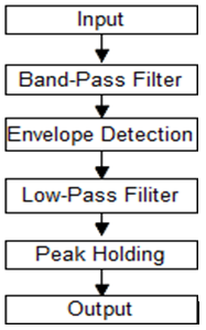
The shock pulse method mainly includes the following four signal processing steps: band-pass filtering, envelope detection, low-pass filtering and peak-holding [6-7]. The principle diagram of SPM analog circuit and its internal structure are shown in Fig.1-5:
Figure 1. The schematic diagram of SPM technology
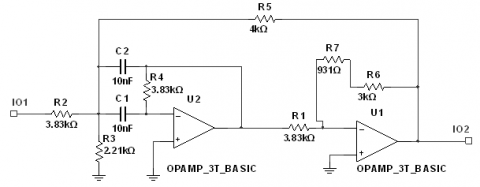
Figure 2. The internal structure of the band-passfilter
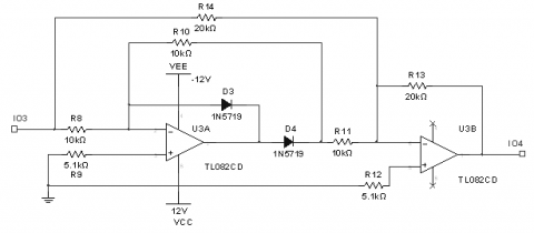
Figure 3. The internal structure of the envelope detector
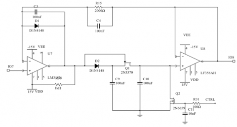
Figure 4. The internal structure of the low-pass filter
Figure 5. The internal structure of the peak holding circuit
The process of extracting the fault signals from the resonance demodulation circuit is divided into three steps:
The model of the rolling bearing used in the experiment is N205EM. The bearing characteristic frequency and its calculating formula are shown in Table 1. The significance of each parameter is as follows:
D-Pitch Diameter; d-Roller Diameter; α/°-Contact Angle; z-Roller Number; n-Speed; fs-Sampling Frequency
Table 1. The parameters of bearing
|
D/mm |
d/mm |
α/° |
z |
n/$r\times {{\min }^{-1}}$ |
fs/Hz |
|
38.5 |
7.5 |
0 |
13 |
1000 |
5120 |
|
Bearing characteristic frequency type |
Formula for calculating the characteristic frequency of bearing |
|
Rotation frequency of inner ring |
${{\text{f}}_{r}}=\frac{n}{60}$ |
|
Scroll through frequency |
${{\text{f}}_{bp}}=\left[ \frac{D}{d}-\left( 1-\frac{d}{D}\cos \alpha \right) \right]{{f}_{r}}$ |
|
Inner pass frequency |
${{\text{f}}_{ip}}=\frac{Z}{2}\left( 1+\frac{d}{D}\cos \alpha \right){{f}_{r}}$ |
|
Outer ring pass frequency |
${{\text{f}}_{op}}=\frac{Z}{2}\left( 1-\frac{d}{D}\cos \alpha \right){{f}_{r}}$ |
|
Holding rotation frequency |
${{\text{f}}_{cp}}=\frac{1}{2}(1-\frac{d}{D}\cos \alpha ){{f}_{r}}$ |
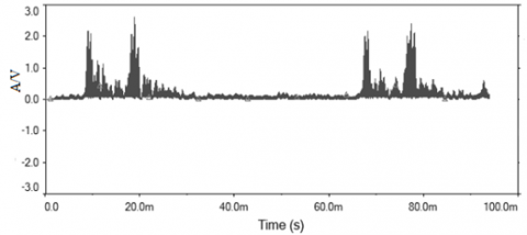
In the experiment, the sampling frequency is 5120Hz, the center frequency is 1200Hz and the bandwidth is 640Hz. With the increase of the noise amplification, the maximum voltage is changed significantly. The following figures are the inner ring, rolling body and the outer ring of the voltage waveform obtained respectively by SPM circuit magnification to 10, 30, 50. The following values can be obtained by calculating:
Figure 6. Output waveform for magnification of 10 of inner ring
Figure 7. Output waveform for magnification of 30 of rolling body
Figure 8. Output waveform for magnification of 10 of inner ring
For different noise amplification cases, three sets of data measured at each magnification of 0,5,10,15... 50. Take the average value and draw out the inner ring, rolling body and the outer ring. The noise magnification - voltage amplitude relation curves are shown in Fig.9-11. It can be obtained from the analysis of the figures:
Figure 9. The curve of the voltage amplitude- noise amplification factor of inner ring
Figure 10. The curve of the voltage amplitude- noise amplification factor of rolling body
Figure 11. The curve of the voltage amplitude- noise amplification factor of outer ring
Define the bearing state level by using the dBm that indicates the maximum extent of damage to the rolling element bearing. Use the subtraction of dBm and dBc to analyze the reason of bearing damage. The shock pulse value of bearing is determined as follows [8] :
Figure 12. The shock pulse value of inner ring
Figure 13. Time domain voltage waveform of inner ring
The output voltage waveform of the fault of the inner ring and its corresponding shock pulse value is shown in Fig.12-13. It can be judged that the bearing is in deterioration tendency. With reference to the definition of dB, it is similar to define dVc for carpet voltage and dVm for maximum voltage. The dVm, maximum value of the shock pulse voltage, is used to define the bearing state level. With n (n≥0) to represent the noise magnification, the judging criterion of using voltage in different noise amplification is concluded as follows:
In this paper, the traditional shock pulse signal processing is improved. The pulse sequence generation circuit made up by the peak holding circuit after the early signal processing(band-pass filtering, envelope detection, low-pass filtering) to generate the rolling bearing shock pulse signal. The adjustment laws of dVm value of the output under different noise amplification conditions is also discussed. Through the above analysis, the following conclusions can be drawn:
The state of the bearing can be judged roughly based on the SPM circuit. The specific fault types can be diagnosed in more detail with the help of other auxiliary methods.
This research is supported by National Natural Science Foundation of China (11227201, 11372199, 11572206) and Natural Science Foundation of Hebei Province (A2014210142).
[1] Mei Hongbin, Vibration monitoring and diagnosis of rolling bearing -- Theory, Method &System. Beijing: Machinery Industry Press,1996.
[2] Wang Xiaoping and Chen Yaowu, SPM method for fault diagnosis of rolling bearing, Mechanical & Electrical Engineering Magazine, vol. 3, pp. 3l-32, 1996.
[3] Yi Liangju, Simple Vibration Diagnosis Technology, Beijing: Mechanical Industry Press, 2003
[4] Zhao Wei, “Fault diagnosis of rolling bearing by shock pulse method,” Bearing, vol. 5, pp. 31-33, 2006.
[5] Zhang Ying, Lv Luyong and Wan Shuting, “The shock pulse method applied on fault diagnosis of rolling bearing,” Petroleum-Chemical Equipment Technology, vol. 28, no. 4, pp. 60-64, 2007.
[6] Huang Baoming and Huanghai, “The improvement and application of real-time on-line rolling bearing monitoring instrument based on shock pulse method,” Journal of Electronic Measurement and Instrument, vol. 15, no. 2, pp. 22-25, 2001.
[7] Li Shanshan, Design and Improvement of Portable Bearing Fault Detector Based on Shock Pulse Method, Instrument Technique and Sensor, 2014 (4): 106-107.
[8] Shen Qinggen, Equipment Fault Diagnosis, Beijing: Chemical Industry Press, 2006.