Zineb Boulaaras* | Abdelaziz Aouiche | Kheireddine Chafaa
© 2023 IIETA. This article is published by IIETA and is licensed under the CC BY 4.0 license (http://creativecommons.org/licenses/by/4.0/).
OPEN ACCESS
The suspension system is classified into three types passive suspension, semi-active, and active suspension. The term a quarter car model originated in the early part of the 20th century. It is considered the best way for studying the effectiveness of vehicle stability. This paper presents the modelling and control of a nonlinear active suspension system for a quarter car, the mathematical model represents a spring-mass (Quarter of the chassis) and unsprung mass (the wheel), with two degrees of freedom (2-DOF) system characterized by a pair of the differential equations. The objective of this work is to determine control strategy to deliver better performance with respect sprung displacement; sprung mass velocity; suspension deflection; peak overshoot; setting time. The active control of the suspension system is achieved using fractional-order PID (FOPID) tuned by particle swarm optimization algorithms (PSO algorithms) because the ordinary FOPID did not give good results, and linear quadratic regulator (LQR) control actions. The results are developed and simulated in MATLAB/Simulink. It is observed that the LQR controller gives better ride comfort by reducing the RMS error and the vibration of various types of road conditions as compared to an intelligent FOPID controller.
fractional-order PID (FOPID), quarter car model, linear quadratic regulator (LQR), RMS error, active suspension system
Vehicle suspension's main task is to separate passenger and vehicular body interactions from oscillations generated by road abnormalities whilst nonetheless preserving continuous wheel-road contact [1]. The major performance requirements of an automotive suspension system are to provide good ride and handling characteristics when random disturbances from the environment and the driver’s maneuvers act upon the moving vehicle [2, 3]. The suspension systems used for improving the ride, it categorized into three types, that is passive suspension systems, semi-active, and active suspension systems [4]. One of the most terms used for the suspension systems is the term « suspension travel », and travel a vehicle's suspension has referred to the distance between the center of the wheel from full extension to full compression of the suspension, and we define it the inches of the wheel can move up and down [5, 6]. The more travel in the suspension, the more time sharks have to dampen or react to the terrain, thus transferring less of that harshness to driver and passengers, giving a smoother, more controlled ride [7]. Therese many works in the past decade were accomplished to design, model, and control the active suspension systems, Manurya, and Bhangal [8], used two control techniques PID and LQR control to suppress the vibration of the system and a comparison between passive and active suspension with road disturbances as input has been made, the authors found LQR control is better in suppressing the vibration as compared to PID control as well as passive suspension.
In reference of Mahmoodabadi and Nejadkourki [9], the authors M.J. Mahmoodabadi, and N. Nejadkouriki proposes an optimal fuzzy adaptative robust proportional-integral-derivative (PID) for a quarter car model with an active suspension system a fuzzy system consisting of the singleton fuzzifier, center average defuzzifier, and the product inference engine is applied to regulate the control parameters, the results show the dominance of the proposed active suspension system. Wang. H.P, and all in the study of Wang et al. [10], proposed the model-free fractional-order sliding mode control (MFFOSMC) and applied it for the nonlinear quarter car of an active suspension system to improve the ride comfort and keep acceptable limits for both suspension deflection and dynamic weel load. In the study Dong et al. and Izadkhah et al. [11, 12], the authors work for the fractional-order PID control of an active suspension, the results in two references show the performance of the active suspension system that uses the FOPID actuator is obviously superior to that of the active suspension system that uses a PID actuator and a passive suspension system.
In this work, we have studied a comparison between fractional-order proportional integral derivative controller tuned by particle swarm optimization, and LQR control, this study applied for the controllers for an active suspension system. The remainder of this paper was organized as follows. In section 2, the dynamic model of nonlinear quarter vehicle active suspension system. In section 3 detailed the design procedure of FOPID, and LQR control. Section 4 gives the simulation results based on Matlab/Simulink and the interpretation of these results. Finally, in section 5 the conclusion of the paper.
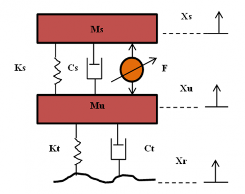
A detailed nonlinear model is used to study the dynamic behavior of a quarter car active suspension system. The model in Figure 1 is shown to a standard quarter vehicle suspension system [13]:
Figure 1. Active suspension of quarter car model
The dynamic equation of the quarter car model of an active suspension with excitation of the road input can be expressed as follows [14, 15]:
$\left\{\begin{array}{c}M_s \ddot{X}_s=-K_s\left(X_s-X_u\right)-C_s\left(\mathrm{X}-\dot{X}_u\right)+F \\ M_u \ddot{X}_u=M_s \ddot{X}_s-K_t\left(X_u-X_r\right)-C_t\left(\dot{X}_u-\dot{X}_r\right)-F\end{array}\right.$ (1)
where:
Ms Sprung mass, Mu Unsprung mass, Ks, Kt is Spring of suspension system, and Spring of wheel and tire, Cs, Ct is Demper of suspension and wheel, Xs, Xu, and Xr is Body Displacement, wheel displacement, and Vertical position of the road profile [16].
Eq. (3) shows the dynamics of the quarter car model defined in a state-space format [17]:
$\left\{\begin{array}{l}\dot{X}=A X+B F+E X_r \\ y=C X+D F+G X_r\end{array}\right.$ (2)
$\begin{aligned} & A=\left[\begin{array}{cccc}-\frac{C_s}{M_s} & -\frac{K_s}{M_s} & \frac{C_s}{M_s} & \frac{K_s}{M_s} \\ 1 & 0 & 0 & 0 \\ \frac{C_s}{M_u} & \frac{K_s}{M_u} & \frac{\left(C_s+C_t\right)}{M_u} & \frac{\left(K_s+K_t\right)}{M_u} \\ 0 & 0 & 1 & 0\end{array}\right], B=\left[\begin{array}{c}\frac{1}{M_s} \\ 0 \\ -\frac{1}{M_u} \\ 0\end{array}\right] \\ & \mathrm{E}=\left[\begin{array}{c}0 \\ 0 \\ \frac{K_t}{M_u} \\ 0\end{array}\right], \mathrm{C}=\left[\begin{array}{cccc}0 & 1 & 0 & 0 \\ 1 & 0 & 0 & 0 \\ -\frac{C_s}{M_s} & -\frac{K_s}{M_s} & \frac{C_s}{M_s} & \frac{K_s}{M_s} \\ 0 & 1 & 0 & -1\end{array}\right], \mathrm{D}=\left[\begin{array}{c}0 \\ 0 \\ \frac{1}{M_s} \\ 0\end{array}\right], \mathrm{G}=0 \\ & \text { With } \dot{X}=\left[\begin{array}{l}\dot{X}_1 \\ \dot{X}_2 \\ \dot{X}_3 \\ \dot{X}_4\end{array}\right] \text {, and } y=\left[\begin{array}{c}X_s \\ \dot{X}_s \\ \ddot{X}_s \\ X_s-X_u\end{array}\right] \\ & \end{aligned}$
The following Table 1 shows the suspension values [18]:
Table 1. Physical parameter values of quarter car suspension model
|
Symbols |
Description and values |
||
|
Description |
Values |
Units |
|
|
Ms |
Sprung Mass |
972.2 |
Kg |
|
Mu |
Unsprung Mass |
113.6 |
Kg |
|
Ks |
Suspension Stiffnes |
42,719.6 |
N/m |
|
Kt |
Wheel Stiffnes |
101,115 |
N/m |
|
Cs |
Suspension Demping |
1,095 |
N.s/m |
|
Ct |
Wheel Demping |
14.6 |
N.s/m |
3.1 Fractional-order PID tuning by PSO algorithm
The fractional-order control turned into designed and analysed via pondlubny. The FOPID delivers more effectiveness than the traditional PID. Based on three parameters of the necessary controller, the FOPID has a further tuning parameter this is indispensable order and differential order µ [19, 20].
The differ-integral operator, denoted by, is a mixed differentiation-integration operator usually utilized in fractional calculus, this operator is a notation for taking both the fractional by-product and the fractional critical in a single expression and is described by [21, 22]:
$\alpha D_t^q=\left\{\begin{array}{lc}\frac{d^q}{d t^q} & q>0 \\ 1 & q=0 \\ \int_\alpha^t(d \tau)^{-q} & q<0\end{array}\right.$ (3)
where, q is the fractional-order which can be a complex number, and a and t are the limits of operation.
There are some definitions for fractional derivatives, the commonly used definition is Grunwald-Letnikov [23], Riemann-Liouville [24], and Caputo definition [25]. The Grunwald-Letnikov Definity:
$\begin{aligned} & a D_t^q f(t)=\frac{d^q f(t)}{d(t-a)^q} =\lim _{N \rightarrow \infty}\left[\frac{t-a}{N}\right]^{-q} \sum_{j=0}^{N-1}(-1)^j\left(\begin{array}{l}q \\ j\end{array}\right) f\left(t-j\left[\frac{t-a}{N}\right]\right)\end{aligned}$ (4)
The Riemann-Liouville is given by definition:
$\begin{array}{r}a D_t^q f(t)=\frac{d^q f(t)}{d(t-a)^q} \frac{1}{\Gamma(n-q)} \frac{d^n}{d t^n} \int_0^t(t -\tau)^{n-q-1} f(\tau) d \tau\end{array}$ (5)
With n is the first integral which is not less than q i.e n-1≤q≤n and Γ is Gamma function definition by equation follows:
$\Gamma(z)=\int_0^{\infty} t^{z-1-t} e^{-t} d t$ (6)
The Caputo fractional derivative gives by:
$L\left\{\alpha D_t^q f(t)\right\}=S^q F(S)-\sum_{k=0}^{n-1} S^k 0 D_t^{q-k-1} f^k(0)$ (7)
With: $n-1 \leq q \leq n \in \mathbb{N}$
The mathematical illustration of the FOPID Controller is as given [26]:
$G(s)=K_p+\frac{K_i}{S^\lambda}+K_d S^\mu$ (8)
The method used for tuning FOPID is PSO algorithms this technique is inspired by the social behavior of birds and fish, it initializes by n-swarm of particles and defined by the position of the particle of a swarm, and velocity of a particle, at iteration, are defined as following equation [27, 28]:
$\begin{aligned} V_{i j}(i+1)=w V_{i j} & +C_1 r_1\left(\text { Pbest }_{i j}-X_{i j}\right) +C_2 r_2\left(\text { Gbest }-X_{i j}\right)\end{aligned}$ (9)
With:
$w=w_{\max }\left(\frac{\text { iter }}{\text { maxiter }}\right)\left(w_{\max }-w_{\min }\right)$ (11)
where, i=1, 2,.., n, and j is a search space r1 and r2 is a random number (0,1). C1 called cognitive parameters pulls each particle towards a local best position. C2 called social parameters pulls the particle towards a global best position, wmax is final weight and wmin initial weight, maxiter is a maximum iteration number, iter is a current iteration number.
The steps of particle swarm algorithm for optimization the FOPID shown in the points follows:
The parameters of FOPID tuned by particle swarm optimization algorithm (PSO) are illustrated in Table 2:
Table 2. Parameters of fractional-order PID controller (FIPID)
|
Values of FOPID |
Parameters of FOPID |
||||
|
Kp |
Ki |
λ |
Kd |
µ |
|
|
|
0.10 |
0.014 |
0.2 |
$12 e^{03}$ |
1 |
3.2 The linear quadratic regulator (LQR) control
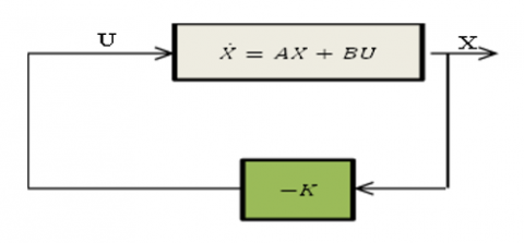
An advantage of the linear quadratic regulator or quadratic optimal control method over the pole-placement method is that the former provides a systematic way of computing the state feedback control gain matrix [29].
We Shall now consider the optimal regulator problem that given the system equation [29-31]:
Determine the matrix K of the optimal control vector:
The state variable feedback configuration is proven below in Figure 2:
Figure 2. State variable feedback configuration
So, as to minimize the performance index:
$J=\int_0^{\infty}\left(X^T Q X+U^T R U\right) d t$ (14)
where, Q and R is a position definite Hermitian or real symmetric.
The design steps are follows [32]:
Solve the following equation for the matrix P [If a position-definite matrix P (n x n) matrix exists (Sure systems might not have a position definite matrix P), the system is stable, or matrix A-BK is stable]:
Substitute this matrix P into the following equation, the resulting matrix K is the optimal matrix:
$K=R^{-1} B^T P$ (16)
Q and R taking by:
$Q=\left[\begin{array}{cccc}10^{-2} & 0 & 0 & 0 \\ 0 & 10^{-9} & 0 & 0 \\ 0 & 0 & 10^{-3} & 0 \\ 0 & 0 & 0 & 10^{-4}\end{array}\right], R=\left[\begin{array}{cc}0.001 & 0 \\ 0 & 0.12\end{array}\right]$
The values of obtained feedback gain matrix of LQR:
$K=\left[\begin{array}{cccc}0.0010 & -0.0001 & -0.0001 & 0.0010 \\ 0.2372 & -0.3078 & 0.0878 & 0.3082\end{array}\right]$
The simulation results are based on the mathematical model of a quarter car, and we take five different types of road disturbance. The inputs for testing the performance of the closed-loop suspension system are a step input signal of amplitude 1(m) and a sinusoidal input signal to represent a bumpy road of amplitude 1(m), a variable -step to represent excavated rood of amplitude 1(m), a noisy road for a road made of high-intensity vibration of 0.2 noise power and 0.1 sample time. The last road in this study is the ramp road of amplitude 0.1(m). The following table (Table 3) explains the description for select different road types:
Table 3. Different road types for testing the model
|
Roads Profiles |
Equation and values |
|
|
Equation |
Values |
|
|
Step Road |
$R(t)=A \times\left\{\begin{array}{l}1 \text { for } t \geq 0 \\ 0 \text { for } t<0\end{array}\right.$ |
A=1m |
|
Sinusoidal Road |
$R(t)=A \times \sin (w t+\Phi)$ |
A=1m |
|
Variable-Step |
$\begin{aligned} R(t)=A \times\left[R_0(t)\right. & -2 R_0(t-3) +2 R_0(t-6) -2 R_0(t-9) +\cdots]\end{aligned}$ |
A=1m |
|
Random Road |
$R=\operatorname{sigma}+\operatorname{randn}(N, 1)+m u$ |
N=0.2 Mu=0.1 Sigma=2 |
|
Ramp Road |
$R(t)=A \times\left\{\begin{array}{l}t \text { for } t \geq 0 \\ 0 \text { for } t<0\end{array}\right.$ |
A=1m |
The objective of this testing with different types of roads is to demonstrate the efficiency of controllers, especially LQR control.
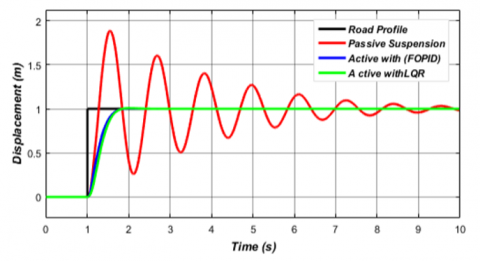
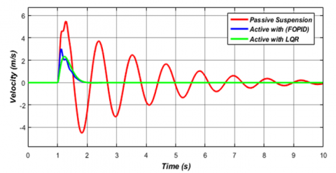
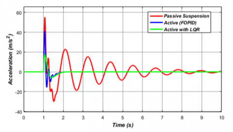
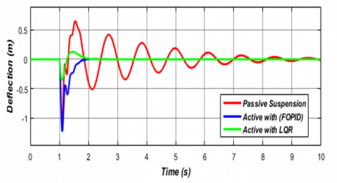
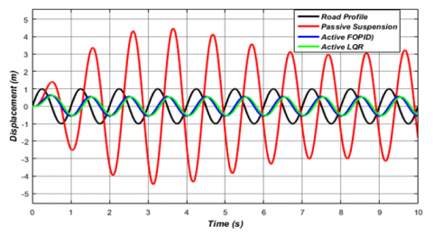
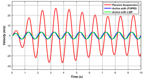
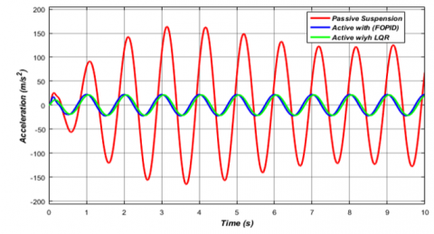
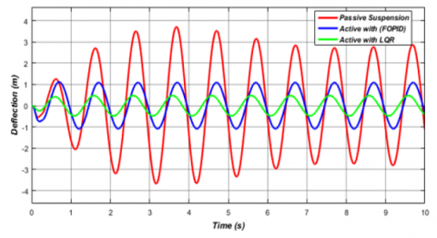
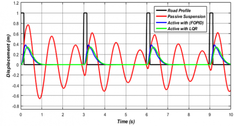
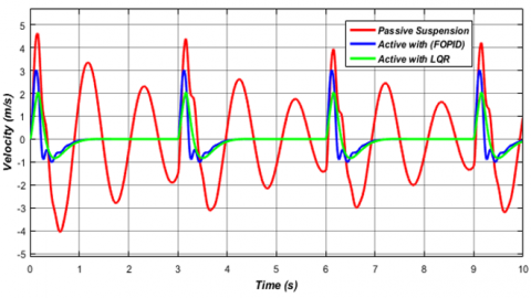
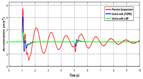
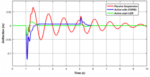
The figures show, the displacement of a car body, velocity, acceleration, and deflection of quarter car suspension for different road profiles. First, road profile 01 is a step input, the simulation results are shown in Figure 3 (a, b, c, and d), It show the comparison between passive, FOPID, and LQR controlled systems for body displacement, velocity, body acceleration, and suspension deflection respectively with road disturbance.
Figure 3a. The respenses for sprung displacement of optimal FOPID and LQR controller of road profile 01
Figure 3b. The respenses for sprung velocity of optimal FOPID and LQR Controller of road profile 01
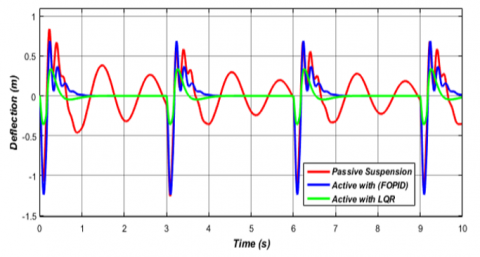
Figure 3 (a, b, c, and d) show a big improvement in performance and suppression of vibration with LQR control as compared to passive suspension and active suspension controlled by FOPID tuned by PSO algorithms. To prove the efficiency of LQR control, we tried the quarter car model other types of roads.
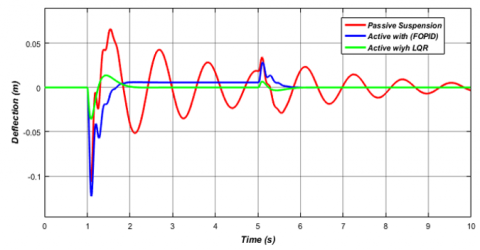
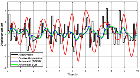
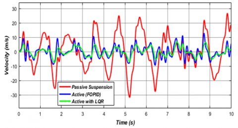
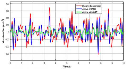
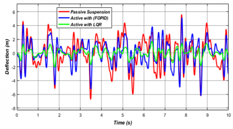
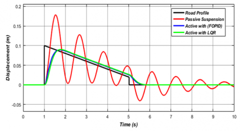
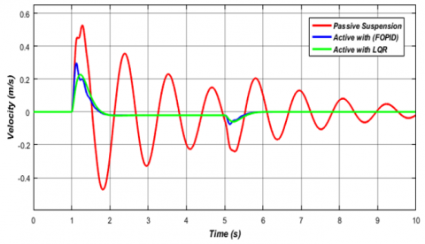
The simulation results are shown in Figure 4 (a, b, c, and d), and Figure 5 (a, b, c, and d) for road profile 02 is a bumpy road, and road profile 03 is an excavated road. It shows the comparison between passive, FOPID, and LQR controlled systems for body displacement, velocity, body acceleration, and suspension deflection with roads disturbances.
The results shown in the figures mentioned above prove the effectiveness of LQR in the stability of the quarter of the car, unlike the Fractional Order PID controller and inactive suspension, and this comparison evident in the RMS error percentage shows in Table 4 and Table 5.
Figure 3c. The respenses for body acceleration of optimal FOPID and LQR controller of road profile 01
Figure 3d. The respenses for suspension deflection of optimal FOPID and LQR controller of road profile01
The simulation results are shown in Figure 6 (a, b, c, and d), and Figure 7 (a, b, c, and d) for road profile 04 is a road that has many vibrations (Noise Road), and road profile 05 is a sloping road (ramp input). It shows the comparison between passive, FOPID, and LQR controlled systems for body displacement, velocity, body acceleration, and suspension deflection with roads disturbances
The results proved that the linear quadratic regulator control (LQR control) gave more stability on rough and steep roads for the car unlike the Fractional-Order controller (FOPID control) optimized by the PSO algorithm, and the passive suspension and this is evident in amplified vibrations in the shaky road and the stability of the car following the road ripples in the inclined road, and this will give more comfort to the passengers and the driver.
Figure 4a. The respenses for sprung displacement of optimal FOPID and LQR controller of road profile 02
Figure 4b. The respenses for sprung velocity of optimal FOPID and LQR controller of road profile 02
Figure 4c. The response for body acceleration of optimal FOPID and LQR controller of road profile 02
Figure 4d. The respenses for suspension deflection of optimal FOPID and LQR controller of road profile 02
Figure 5a. The respenses for sprung displacement of optimal FOPID and LQR controller of road profile 03
Figure 5b. The respenses for sprung velocity of optimal FOPID and LQR controller of road profile 03
Figure 5c. The respenses for body acceleration of optimal FOPID and LQR controller of road profile 03
Figure 5d. The respenses for suspension deflection of optimal FOPID and LQR controller of road profile 03
Figure 6a. The respenses for sprung displacement of optimal FOPID and LQR controller of road profile 04
Figure 6b. The respenses for sprung velocity of optimal FOPID and LQR controller of road profile 04
Figure 6c. The respenses for body acceleration of optimal FOPID and LQR controller of road profile 04
Figure 6d. The respenses for suspension deflection of optimal FOPID and LQR controller of road profile 04
Figure 7a. The respenses for sprung displacement of optimal FOPID and LQR controller of road profile 05
Figure 7b. The respenses for sprung velocity of optimal FOPID and LQR controller of road profile 05
Figure 7c. The respenses for body acceleration of optimal FOPID and LQR controller of road profile 05
Figure 7d. The respenses for suspension deflection of optimal FOPID and LQR controller of road profile 05
Simulation results show improvement in the ride comfort performance and suppression of vibration noise with LQR control and FOPID control as compared to passive with all types of road disturbance, in Figure 4 to Figure 7 we found the LQR control minimize the RMS error for all road disturbance which the min and max value of RMS error when used FOPID control, is 11% to 84%, and after using LQR increased the reduction of RMS between 12% for a min, 85% for max value. LQR control system improvement in terms of setting time and maximum overshoot in suspension deflection and body acceleration, but it gives a slow response unlike the FOPID control scheme gives a faster response but higher amplitude in a case of suspension deflection, velocity, and body acceleration.
The Table 4 Illustrated a comparison of RMS error between FOPID and LQR control systems, and the Table 5 shows the reduction of error for all types of roads used:
Table 4. RMS error between passive and active suspension controlled by FOPID and LQR control
|
Methods |
RMS Error |
|||||
|
Step Input |
Sine Input |
Pulse Input |
Noise Input |
Ramp Input |
||
|
Passive |
9.612e-1 |
2.400 |
3.54e-1 |
2.120 |
5.66e-2 |
|
|
Active with FOPID |
8.52e-1 |
3.68e-1 |
1.69e-1 |
5.91e-1 |
3.98e-2 |
|
|
Active with LQR |
8.46e-1 |
3.55e-1 |
1.53e-1 |
5.66e-1 |
3.94e-2 |
|
Table 5. Reduction of RMS error
|
Methods |
Reduction (%) of RMS Error |
||||
|
Step Input |
Sine Input |
Pulse Input |
Noise Input |
Ramp Input |
|
|
Passive |
0% |
0% |
0% |
0% |
0% |
|
Active with FOPID |
11% |
84% |
51% |
72% |
30% |
|
Active with LQR |
12% |
85% |
57% |
73% |
42% |
In this paper, the fractional-order PID (FOPID) and linear quadratic regulator (LQR) controllers are effectively designed using MATLAB/SIMULINK. Both controllers can stabilize the suspension system very effectively compared to a passive suspension system. The previous results showed in Figures (Figure 4 to Figure 7) illustrated the FOPID controller scheme gives a faster response where rise time takes value 441.629 (ms) unlike LQR control the value of rise time is 454.581 (ms), but the LQR control system gives much better results in the ride comfort performance compared to an active suspension system controlled by FOPID control and passive suspension.
[1] Riduan, F.M. (2018). Review on active suspension system. In ShS web of conferences. EDP Sciences, 49: 02008.
[2] Li, W., Du, H., Ning, D., Li, W. (2019). Robust adaptive sliding mode PI control for active vehicle seat suspension systems. In 2019 Chinese Control And Decision Conference (CCDC), 5403-5408. https://doi.org/10.1109/CCDC.2019.8832368
[3] Daniyan, I.A., Mpofu, K., Osadare, D.F. (2018). Design and simulation of a controller for an active suspension system of a rail car. Cogent Engineering, 5(1): 1545409. https://doi.org/10.1080/23311916.2018.1545409
[4] Huang, Y., Na, J., Wu, X., Gao, G. (2020). Robust adaptive parameter estimation and control for vehicle active suspension systems. In Vibration Control and Actuation of Large-Scale Systems, 225-252. https://doi.org/10.1016/B978-0-12-821194-6.00008-1
[5] Goodarzi, A., Khajepour, A. (2017). Vehicle suspension system technology and design. Synthesis Lectures on Advances in Automotive Technology, 1(1): i-77. https://doi.org/10.2200/S00767ED1V01Y201704MEC002
[6] Pan, H., Sun, W. (2018). Nonlinear output feedback finite-time control for vehicle active suspension systems. IEEE Transactions on Industrial Informatics, 15(4): 2073-2082. https://doi.org/10.1109/TII.2018.2866518
[7] Abdelkareem, M.A., Xu, L., Ali, M.K.A., Elagouz, A., Mi, J., Guo, S., Zuo, L. (2018). Vibration energy harvesting in automotive suspension system: A detailed review. Applied energy, 229: 672-699. https://doi.org/10.1016/j.apenergy.2018.08.030
[8] Maurya, V.K., Bhangal, N.S. (2018). Optimal control of vihicle active suspension system. Journal of Automation and control engineering, 6: 1.
[9] Mahmoodabadi, M.J., Nejadkourki, N. (2020). Optimal fuzzy adaptive robust PID control for an active suspension system. Australian Journal of Mechanical Engineering, 1-11. https://doi.org/10.1080/14484846.2020.1734154
[10] Wang, H.P., Mustafa, G.I., Tian, Y. (2018). Model-free fractional-order sliding mode control for an active vehicle suspension system. Advances in Engineering Software, 115: 452-461. https://doi.org/10.1016/j.advengsoft.2017.11.001
[11] Dong, X., Zhao, D., Yang, B., Han, C. (2016). Fractional-order control of active suspension actuator based on parallel adaptive clonal selection algorithm. Journal of Mechanical Science and Technology, 30(6): 2769-2781. https://doi.org/10.1007/s12206-016-0538-2
[12] Izadkhah, A., Nouri, K., Nikoobin, A. (2020). Proportional integral derivative control of fractional–order for a quarter–vehicle active suspension system. Romanian Journal of Physics, 65: 103.
[13] Haddar, M., Chaari, R., Baslamisli, S.C., Chaari, F., Haddar, M. (2019). Intelligent PD controller design for active suspension system based on robust model-free control strategy. Proceedings of the Institution of Mechanical Engineers, Part C: Journal of Mechanical Engineering Science, 233(14): 4863-4880. https://doi.org/10.1177/0954406219836443
[14] Moaaz, A.O., Ghazaly, N.M. (2019). Fuzzy and PID controlled active suspension system and passive suspension system comparison. International Journal of Advanced Science and Technology, 28(16): 1721-1729.
[15] Ali, A.B.K., Hameed, M.M. (2019). A study, modeling and smart control of quarter car suspension system. International Journal of Computer Science and Mobile Computing, 8(4): 157-166.
[16] Turnip, A., Panggabean, J.H. (2020). Hybrid controller design based magneto-rheological damper lookup table for quarter car suspension. International Journal of Artificial Intelligence, 18(1): 193-206.
[17] Nichiţelea, T.C., Unguritu, M.G. (2022). Design and comparisons of adaptive harmonic control for a quarter-car active suspension. Proceedings of the Institution of Mechanical Engineers, Part D: Journal of Automobile Engineering, 236(2-3): 343-352. https://doi.org/10.1177/09544070211019251
[18] Liang, Y.J., Wu, S.L. (2013). Optimal vibration control for tracked vehicle suspension systems. Mathematical Problems in Engineering, 2013. https://doi.org/10.1155/2013/178354
[19] Swethamarai, P., Lakshmi, P. (2020). Adaptive-fuzzy fractional order pid controller-based active suspension for vibration control. IETE Journal of Research, 1-16. https://doi.org/10.1080/03772063.2020.1768906
[20] Aboelela, M.A., Hennas, R.H.M. (2018). Development of a fractional-order PID controller using adaptive weighted PSO and genetic algorithms with applications. In Fractional Order Systems, 511-551. https://doi.org/10.1016/B978-0-12-816152-4.00017-0
[21] Chen, Y., Petras, I., Xue, D. (2009). Fractional order control-a tutorial. In 2009 American control conference, 1397-1411. https://doi.org/10.1109/ACC.2009.5160719
[22] Monje, C.A., Chen, Y., Vinagre, B.M., Xue, D., Feliu-Batlle, V. (2010). Fractional-order systems and controls: fundamentals and applications. Springer Science & Business Media. https://doi.org/10.1007/978-1-84996-335-0
[23] Poluby. (1999). Fractional-Order system and PIλDµ controller. IEEE Transactions on Automatic Control, 44(1): 208-719.
[24] Zhang, F., Yang, C., Zhou, X., Gui, W. (2018). Fractional-order PID controller tuning using continuous state transition algorithm. Neural Computing and Applications, 29(10): 795-804. https://doi.org/10.1007/s00521-016-2605-0
[25] Dulău, M., Gligor, A., Dulău, T.M. (2017). Fractional order controllers versus integer order controllers. Procedia Engineering, 181: 538-545. https://doi.org/10.1016/j.proeng.2017.02.431
[26] Lamba, R., Sondhi, S., Singla, S.K. (2020). Reduced order model based FOPID controller design for power control in Pressurized Heavy Water Reactor with specific gain–phase margin. Progress in Nuclear Energy, 125: 103363. https://doi.org/10.1016/j.pnucene.2020.103363
[27] Haji, V.H., Monje, C.A. (2017). Fractional order fuzzy-PID control of a combined cycle power plant using particle swarm optimization algorithm with an improved dynamic parameters selection. Applied soft computing, 58: 256-264. https://doi.org/10.1016/j.asoc.2017.04.033
[28] Latha, K., Rajinikanth, V., Surekha, P.M. (2013). PSO-based PID controller design for a class of stable and unstable systems. International Scholarly Research Notices, 2013. https://doi.org/10.1155/2013/543607
[29] Samsuria, E., Sam, Y.M., Ramli, L. (2018). Active suspension control by using linear quadratic regulator and sliding mode control techniques with optimisation. In 2018 IEEE Conference on Systems, Process and Control (ICSPC), 135-140. https://doi.org/10.1109/SPC.2018.8704162
[30] Putra, S.M., Yakub, F., Ali, M.S.M., Rudin, N.F.M.N., Rasid, Z.A., Abu, A., Rashid, M.Z.A. (2018). Improvement on ride comfort of quarter-car active suspension system using linear quadratic regulator. In Proceedings of the Second International Conference on the Future of ASEAN (ICoFA) 2017, 2: 431-441. https://doi.org/10.1007/978-981-10-8471-3_43
[31] Jibril, M. (2020). Quarter car active suspension system design using optimal and robust control method. International Research Journal of Modernization in Engineering Technology and Science, 2(3): 197-207.
[32] Ramakrishnan, R., Nachimuthu, D.S. (2021). Design of state feedback LQR based dual mode fractional-order PID controller using inertia weighted PSO algorithm: For control of an underactuated system. Journal of The Institution of Engineers (India): Series C, 102(6): 1403-1417. https://doi.org/10.1007/s40032-021-00756-x