Bilal Abdullah Nasir
© 2022 IIETA. This article is published by IIETA and is licensed under the CC BY 4.0 license (http://creativecommons.org/licenses/by/4.0/).
OPEN ACCESS
This paper presents a novel external secondary self-excitation capacitance and chopper resistance across the diode bridge rectifier in the rotor circuit to control the voltage and frequency of 3-phase, wound-rotor, slip-ring, induction generator (WRSRIG). The problem related to the excitation- capacitance from the rotor side is the required large excitation capacitance to enhance the generator performance in a wide - range. In the present proposed method, a dynamic excitation capacitance is used in the H-Bridge inverter circuit connected in series with a chopper resistance across a 3-phase diode bridge rectifier in the rotor circuit. The duty ratios of the H-bridge thyristor elements and the thyristor chopper element are varied to emulate the excitation-capacitance as well as external-rotor resistance values dynamically, and to be used as terminal voltage and its frequency control. The dynamic excitation-capacitance is used to control the terminal voltage, while the dynamic external rotor resistance is used to control the generator speed (frequency). To study the performance of the WRSRIG a dynamic model is presented in this paper in D-Q axes rotating synchronously in a reference frame. The dynamic model takes into account all the machine parameters, such as stator and rotor - iron core losses, stator and rotor - stray load losses, dynamic saturation of the magnetizing inductance, rotor harmonic losses generated due to switching action of the bridge rectifier, reduction voltage in the rotor circuit due to the over-lap phenomenon and rotor external resistance losses. The new proposed equivalent circuit of the WRSRIG will become an efficient method for studying the performance characteristics of the generator and to be used as a suitable tool for an algorithm of the vector control analysis.
wound rotor slip-ring induction generator, chopper resistance, switched capacitance in H-bridge inverter, synchronously rotating reference frame
When the induction machine is driven with over synchronous speed by a prime-mover and a selected suitable value of capacitance is connected across the stator terminals in squirrel-cage induction machines or across rotor terminals in wound rotor slip-ring machines, the machine is called a self-excited induction generator (SEIG). These SEIG's has been largely utilized in isolated or stand-alone generation system that used wind or hydro-power turbines [1-3]. In a given speed and excitation- capacitance, the building-up process of the terminal voltage is mainly determined by the saturated magnetizing inductance of the machine [4]. Both terminal voltage and frequency of the SEIG are varying with the load although the speed of the rotor remained constant. There have many research efforts on solving the problem of control of line voltage and frequency of the squirrel-cage induction generator [5-10]. But very little effort has been devoted to the utilization of wound-rotor, slip-ring, induction generator in isolated areas applications [1]. Different models of analysis of the WRSRIG have been used. The steady-state model includes the loop-impedance method or nodal-admittance method [11-14]. The machine dynamical model, based on the generalized theory of induction machines [15, 16].
However, the steady-state model cannot deal with the dynamic characteristics of the generator, while the dynamic models are considered the excitation capacitance in the stator side only. In all of these models, the iron core losses, the stray load losses, magnetizing saturation, harmonic loss, and the over-lap reduction voltage in the rotor circuit are not considered. This research paper proposed a novel voltage and frequency control circuit of WRSRIG, consisting of a chopper external resistance connected in series with H-Bridge inverter switched -excitation capacitance across diode bridge rectifier in the rotor circuit.
A novel equivalent circuit is proposed in steady-state operation and D-Q axes dynamic model in the synchronously rotating frame. These equivalent circuit models can deal with studying transient and steady-state performance characteristics of the generator. In these models, all the machine parameters are included, such as iron core losses, stray load losses, magnetizing saturation, reduction voltage due to the over-lap phenomenon, and the harmonic losses.
The proposed scheme of WRSRIG and its steady-state equivalent circuit is shown in Figure 1. The machine can be operated as an induction generator if the rotor is driven over synchronous speed by wind or hydro turbine.
The excitation capacitance connected across H-bridge inverter in the rotor circuit to control the stator terminal voltage by varying the duty ratio Ɣinv of the inverter switches. The effective external rotor excitation capacitance can be calculated as [17]:
$C_{r e f}=C_{r} /\left(2.Ɣ_{i n v}-1\right)^{2}$ (1)
where, Cr is the switched excitation capacitance in the rotor circuit. This capacitance appears in series with the external chopper resistance across the diode bridge rectifier in the rotor circuit. The frequency of terminal voltage can be controlled by varying the external resistance (Rex) in the rotor circuit. The chopper-thyristor switch is connected across the resistance. The effective - resistance appears across the bridge rectifier in the rotor circuit depending on the duty ratio Ɣch of the chopper and can be calculated as [18]:
$Ŕ _{e f f}=\left(1Ɣ_{c h}\right)^{2} * Ŕ _{e x}$ (2)
In this method, the terminal voltage and its frequency can be controlled with a wide range of load variations.
Due to the presence of leakage reactance's in the rotor windings of the WRSRIG, the commutation of currents among the rotor phases between the terminals of the bridge rectifier does not occur instantaneously. There is a period of current overlap between the phases. This leads to a reduction in the rectified voltage. The reduction voltage due to the over-lap can be obtained as:
$V_{d r}=3 * \acute{X}_{\ell r} * I_{d} / \pi$ (3)
where, $X_{\ell r}$ is the leakage reactance of the rotor per phase reflected onto the stator.
Id is the rectified DC output current of the bridge rectifier. The current Id can be obtained in terms of the rotor phase current referred to the stator side (ĺr) as:
$I_{d}=\sqrt{3} * ĺ_{r} / \sqrt{2}$ (4)
Then from (3) and (4), the reduction voltage due to the over-lap can be obtained as:
$V_{d r}=1.17 * \cdot \acute{X}_{\ell r}$ (5)
Then the over-lap reactance ($X_{o \ell}$) in the rotor circuit can be represented as:
$\acute{X}_{o \ell}=1.17 * \acute{X}_{\ell r}$ (6)
Due to the rectification process of the diode bridge rectifier, a harmonic loss is generated in the rotor circuit and can be represented by a resistance (Ŕh ) per phase of the rotor circuit as [18]:
$Ŕ_{h}=\left[Ŕ_{r}+\left(\frac{1}{2}\right) * Ŕ_{e f f}\right] *\left(\frac{\pi^{2}}{9}-1\right)$ (7)
where, Ŕr is the rotor resistance per phase reflected onto the stator circuit.
Stray load loss resistances $\left(R_{s s s \ell}^{*} \& Ŕ_{r s s \ell}\right)$ of the stator and rotor circuits in the steady-state equivalent circuit of the WRSRIG can be calculated as [19]:
$R_{s s s \ell}=\left(\omega_{s} \cdot L_{\ell s}\right)^{2} * R_{s} /\left[R_{s}^{2}+\left(\omega_{s} . L_{\ell s}\right)^{2}\right]$ (8)
$R_{r s s \ell}=\frac{S \cdot\left(\omega_{s \ell} \cdot \acute{L}_{\ell r}\right)^{2} * \acute{R}_{r}}{\left(\acute{R}_{r}\right)^{2}}=\frac{s^{2} \cdot\left(\omega_{s} \cdot \acute{L}_{\ell r}\right)^{2}}{\acute{R}_{r}}$ (9)
where, $L_{\ell s}$ and $L_{\ell r}^{\prime}$=stator and rotor leakage inductances. ωs is the angular speed of the stator terminal voltage. Rs and Ŕr are stator and rotor winding resistances respectively. If the machine operates near the synchronous speed the slip (s) is very small and the rotor circuit stray load loss resistance ($Ŕ_{r s s \ell}$) can be neglected.
(a) Schematic diagram of wound- rotor slip-ring induction generator
(b) Steady-state equivalent circuit of WRSRIG
Figure 1. The proposed scheme of WRSRIG and steady-state equivalent circuit
(a) D-axis model
(b) Q-axis model
Figure 2. Modified equivalent circuit of SEIG in D-Q axes of synchronously rotating reference frame
In the proposed D-Q axes equivalent circuit shown in Figure 2, the modified series equivalent of stator and rotor iron core resistances (Rssic & Rrsic) can be reflected as voltage drops in the stator and rotor circuits to take the effect of iron core losses without increasing the order of the system differential equations. These resistances as well as the equivalent dynamic inductance (Lm) can be calculated as [20]:
$R_{s s i c}=R_{s i c} \cdot\left(\omega_{S} \cdot L_{M}\right) /\left[R_{\text {sic }}^{2}+\left(\omega_{S} \cdot L_{M}\right)^{2}\right]$ (10)
$R_{r s i c}=s . R_{s s i c}$ (11)
$L_{m}=L_{M} \cdot R_{\text {sic }}^{2} /\left[R_{\text {sic }}^{2}+\left(\omega_{s} \cdot L_{M}\right)^{2}\right]$ (12)
where, Rsic is the stator iron core resistance which can be calculated from the no-load test of the machine. Lm is the dynamic magnetizing inductance which can be found from the no-load test in terms of magnetizing current (Im), represented by a polynomial curve-fitting technique as:
$L_{M}=0.04765 * I_{m}^{5}-0.5129 * I_{m}^{4}+2.18 * I_{m}^{3}-4.57 * I_{m}^{2}+4.636 * I_{m}+0.25$ (13)
The parameters of stator and rotor voltages of the WRSRIG with excitation capacitors derived from the proposed circuit are shown in Figure 2 as:
$v_{s d}=\left(R_{s}+R_{s s s \ell}\right) \cdot i_{s d}+\frac{d \psi_{s d}}{d t}+R_{s s i c} \cdot i_{m d}-\omega_{s} \cdot \psi_{s d}$ (14)
$v_{s q}=\left(R_{s}+R_{s s s \ell}\right) \cdot i_{s q}+\frac{d \psi_{s q}}{d t}+R_{s s i c} . i_{m q}+\omega_{s} . \psi_{s q}$ (15)
$v_{c d}=\left(Ŕ_{r}+Ŕ_{r s s \ell}+Ŕ_{h}+Ŕ_{e f f}\right) í_{r d}+R_{r s i c} \cdot i_{m d}+\frac{d' \psi_{r d}}{t d}-\omega_{s \ell} \cdot \acute{\psi}_{r q}-\omega_{s \ell} \cdot \acute{\psi}_{r q o}$ (16)
$v_{c q}=\left(Ŕ_{r}+Ŕ_{r s s \ell}+Ŕ_{h}+Ŕ_{e f f}\right) \cdot í_{r q}+R_{r s i c} \cdot i_{m q}+\frac{\acute{d} \psi_{r q}}{t d}+\omega_{s \ell} \cdot \acute{\psi}_{r d}+\omega_{s \ell} \cdot\acute{\psi}_{r d o}$ (17)
where $\omega_{s \ell}$ is the slip speed $=\left(\omega_{s}-\omega_{r}\right) \mathrm{rad} . / \mathrm{sec} .$ (18)
where, ωr is the rotor speed of the generator in electrical. rad./sec. ψsd, ψsq, $\acute{\psi}_ {rd}$and $\acute{\psi}_ {rq}$ are the stator and rotor flux linkage in d-q axes, and defined as:
$\psi_{s d}=L_{\ell s} \cdot i_{s d}+L_{m} \cdot i_{m d}$ (19)
where $\omega_{s \ell}$ is the slip speed $=\left(\omega_{s }-\omega_{r}\right) \mathrm{rad} . / \mathrm{sec} .$ (20)
$\acute{\psi}_{r d}=\acute{L}_{\ell r} \cdot i_{r d}+\acute{L}_{o \ell}\acute{i}_{r d}+L_{m} \cdot i_{m d}+\acute{\psi}_{r d o}$ (21)
$\acute{\psi}_{r q}=\acute{L}_{\ell r} \cdot i_{r q}+\acute{L}_{o \ell} \cdot i_{r q}+L_{m} \cdot i_{m q}+\acute{\psi}_{r q o}$ (22)
$i_{m d}=i_{s d}+\acute{l}_{r d}$ (23)
$i_{m q}=i_{s q}+\acute{l}_{r q}$ (24)
where, $\acute{\psi}_ {rdo}$ and $\acute{\psi}_ {rqo}$=the residual rotor linkage fluxes in the D and Q axes, respectively.
$\acute{v}_{c d}=\int\left(\frac{\acute{l}_{r d}}{C_{r e f}}+\omega_{s l} \cdot v_{c q}\right) d t+V_{c d o}$ (25)
$\acute{v}_{c q}=\int\left(\frac{\acute{l}_{r q}}{C_{r e f}}-\omega_{s l} \cdot v_{c d}\right) d t+V_{c q o}$ (26)
where, $\acute{V}_ {cdo}$ and $\acute{V}_ {cqo}$ are the initial voltages of the rotor excitation capacitor in the D-Q synchronously rotating frame?
$i_{m}=\sqrt{i_{m d}^{2}+i_{m q}^{2}}$ (27)
$v_{c m}=\sqrt{\acute{v}_{c d}^{2}+\acute{v}_{c q}^{2}}$ (28)
where, im is the maximum magnetizing current and vcm is the maximum capacitance voltage.
The electromagnetic torque generated by WRSRIG is calculated as:
$T_{e}=\left(\frac{3}{2}\right) \cdot\left(P_{p}\right) \cdot\left(L_{m}\right) \cdot\left(i_{s d} \cdot \acute{l}_{r q}-{i}_{s q} \cdot \acute{l}_{r d}\right)$ (29)
The active output power of WRSRIG is calculated as:
$P_{t}=\frac{3}{2}\left[v_{s d} \cdot i_{s d}+v_{s q} \cdot i_{s q}\right]$ (30)
The reactive output power can be calculated as:
$Q_{t}=\frac{3}{2}\left[v_{s q} \cdot i_{s d}-v_{s d} \cdot i_{s q}\right]$ (31)
The machine power factor can be calculated as:
$P \cdot F=\cos \phi=\frac{P_{t}}{\sqrt{P_{t}^{2}+Q_{t}^{2}}}$ (32)
The minimum capacitance in the external rotor circuit is needed to generate the rated terminal voltage at no-load and rated machine speed conditions derived from the steady-state equivalent circuit of the WRSRIG in Figure 1 as:
$C_{r e f(\max )}=1 /\left[\omega_{r c}^{2}\left(L_{m}+L_{\ell r}+\acute{L}_{o \ell}\right)\right]$ (33)
$C_{r e f(\min )}=1 /\left[\omega_{r m}^{2} \cdot\left(L_{m}+L_{\ell r}+\acute{L}_{o \ell}\right)\right]$ (34)
where, ωrc=the machine cut-off or minimum rotor speed in (electrical rad./second).
ωrm is the maximum (above synchronous speed) allowable machine speed in electrical radian/second.
The minimum, or maximum excitation capacitance depends on the maximum or minimum generator rotor speed (ωr) in electrical rad./sec.
$\omega_{r c}=\omega_{s} \cdot\left(1-S_{m}\right)$ (35)
$\omega_{r m}=\omega_{s} \cdot\left(1+S_{m}\right)$ (36)
where, ωs=the machine synchronous-speed or angular-frequency in electrical. rad./esc.
Sm=the machine slip at maximum torque or maximum power. The slip is positive when the machine rotates under synchronous speed, and it is negative when the machine rotates above synchronous speed.
The dynamic simulation model of the WRSRIG system has been developed in Matlab / Simulink. The experimental setup consists of DC. Motor coupled with the WRSRIG system. The DC motor is a separately excited type and used as a prime-mover to the WRSRIG.
The WRSRIG is driven at a above synchronous speed, and then a capacitor and external resistance are connected with their chopper and H-bridge inverter at the rotor side. The specifications of the WRSRIG are given as follow:
3-phase, wound rotor slip-ring, delta-connected, 220 V, induction machine with the following data:
$P_{\text {out }}=1500 W, N_{s}=1500$ r.p.m, $I_{\ell}=6.6 \mathrm{~A}, P_{p}=2, \cos \phi=0.8$
$R_{s}=5.1 \Omega, Ŕ_{r}=3.5 \Omega, L_{\ell s}=16 \mathrm{mH}, L_{\ell r}=24 \mathrm{mH}, L_{M}=0.28 \mathrm{H}$
$R_{s i c}=300 \Omega$ at rated voltage, $J=0.03 k_{g} \cdot m^{2}, D=0.003 \frac{N . m}{\left(\frac{r a d}{s e c}\right)}, C_{r(\min )}=30 \mu F$
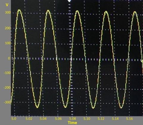
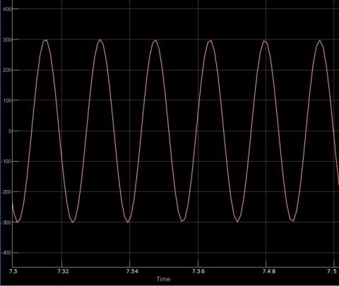
Figure 3 shows the Matlab and experimental results for the starting-up condition of the generator terminal voltage. Figure 4 shows the Matlab and practical results of the steady-state terminal voltage of the WRSRIG. From these figures, there is a very close agreement between the simulation and practical results, which indicates the validity of the proposed dynamic simulation model. The accurate results of the dynamic model are obtained due to considering into account the iron core losses, stator and rotor stray load losses, the dynamic saturation in magnetizing inductance, and the rotor over-lap and harmonic losses.
Figure 3. Experimental result (a) and Matlab simulation result (b) of building–up generator terminal voltage at the no-load condition
(a)
(b)
Figure 4. Experimental result (a) and Matlab simulation result (b) of the steady-state generator phase voltage
Figures 5 and 6 show the Matlab results of WRSRIG electromagnetic torque and per phase output active power of the generator. The results show the harmonic torque and harmonic power loss due to the rectification process of the diode bridge rectifier; a harmonic loss is generated in the rotor circuit. Figure 7 shows the terminal phase voltage due to a sudden disconnection of the excitation capacitance from the rotor circuit. This indicates that the generator cannot be operated without specific excitation capacitance.
Figure 5. Matlab result of electromagnetic torque
Figure 6. Matlab result of active power per phase
Figure 7. Practical Phase voltage due to sudden disconnection of excitation capacitance
A comprehensive dynamic model of WRSRIG has been considered in this work takes into account the iron core losses, stator and rotor stray load losses, the dynamic saturation in magnetizing inductance, and the rotor over-lap and harmonic losses without increasing the number of state-space differential equations. The WRSRIG equivalent circuit is modified to deal with all machine parameters without losing the accuracy of performance calculation. The duty ratio of the thyristor chopper in the rotor circuit is used to control the electromagnetic torque as well as the frequency (rotor speed) of the generator. The duty ratio of the H-bridge inverter is used to vary the effective excitation capacitance in the rotor circuit to control the terminal voltage of the generator.
The proposed control circuits and the corresponding dynamic and steady-state equivalent circuits can be used as an efficient method of studying the performance characteristics for this type of induction generator.
[1] Chan, T.F., Nigim, K., Lai, L.L. (2004). Voltage and frequency control of self-excited slip-ring induction generators. IEEE Transaction on Energy Conversion, 19(1): 80-87. https://doi.org/10.1109/TEC.2003.821860
[2] Sandhu, K.S., Jain, S.P. (2008). Analysis of wound rotor self-excited induction generators. In Proceedings of the 2nd WSEAS International Conference on Circuits, Systems, Signal and Telecommunications, pp. 164-168.
[3] Shaltot, A.A., Abdo, T.M., Halouda M.M., Besheer, A.H. (2009). Voltage and frequency control of self-excited slip ring induction generator driven by wind turbine. 13th Middle East Power Systems Conference, MEPCON' 2009, Assuit University, Egypt, pp. 57-62. https://www.researchgate.net/publication/278004554.
[4] Devabhaktuni, S., Kumar, S.V.J. (2012). Different self- excitation techniques for slip ring self-excited induction generator. International Journal of Computer Applications (0975-8887), 38(2): 19-26. https://doi.org/10.5120/4580-6756
[5] Youssef, K.H., Wahba, M.A., Yousef, H.A., Sebakhy, O.A. (2008). A new method for voltage and frequency control of stand-alone self-excited induction generator using PWM converter with variable DC link voltage. 2008 American Control Conference, Westin Seattle Hotel, Seattle, Washington, USA, pp. 2486-2491. https://doi.org/10.1109/ACC.2008.4586864
[6] Hanafy, H.H., Gesraha, A.M., Abd-Elaziz, M.M., Zobaa, A.F. (2008). Voltage and frequency control of self-excited short-shunt induction generator. Journal of Engineering and Computer science, Qassim University, 1(2): 95-108. https://www.researchgate.net/profile/Ahmed-Zobaa/publication/264842827.
[7] Singh, S., Tiwari, A.N. (2013). Voltage and frequency controller for self-excited induction generator in micro hydro-power plant: Review. International Journal of Advanced Research in Electronics and Communication Engineering (IJARECE), 2(2): 214-219.
[8] Taoufik, M., Abdelhamid, B., Lassad, S. (2018). Stand-alone self-excited induction generator driven by a wind turbine. Alexandria Engineering Journal, Alexandria University, 57(2): 781-786. https://doi.org/10.1016/j.aej.2017.01.009
[9] Nasir, B.A., Daoud, R.W. (2020). Modeling of wind turbine-self excited induction generator system with pitch angle and excitation capacitance control. AIP Conference Proceedings, 2307: 020022. https://doi.org/10.1063/5.0032904
[10] Nasir, B.A. (1997). Theory and design of traveling wave induction heaters for flat metallic workpieces. Ph.D. Thesis, AL–Mustansiriyah University, Baghdad, Iraq. https://www.researchgate.net/publication/356537148.
[11] Devabhaktuni S., Kumar, S.V.J. (2012). Selection of capacitors for the self-excited slip ring induction generator with external rotor capacitance. Journal of Energy Technologies and Policy, 2(2): 66-77.
[12] Mathankumar, S., Loganathan, P. (2012). Modeling and analysis of self-excited slip ring induction generator using Newton Raphson method. International Journal of Engineering Research and Development, 2(7): 26-35.
[13] Gupta, S., Thakre, K., Gupta, G. (2013). Dynamic response of wound rotor induction generator for wind energy application. Journal of Innovative Systems Design and Engineering, 4(6): 69-74.
[14] Jain, A., Shrivastav, R. (2017). Analysis of self-excited induction generator using GUI. International Journal of Engineering Research and Technology (IJERT), Special Issue, 5(3): 1-3. https://www.ijert.org/research/analysis-of-self-excited-induction-generator-using-gui-IJERTCONV5IS03056.pdf.
[15] Barakat, M., Elmasry, S., Bahgat, M.E., Sayed, A.A. (2012). Effect of rotor current control for wound rotor induction generator on the wind turbine performance. International Journal of Power Electronics and Drive System (IJPEDS), 2(2): 117-126. https://doi.org/10.11591/ijpeds.v2i2.213
[16] Jayaram, P., Hariharan, S., (2017). DC excitation control for an autonomous wound rotor induction generator using embedded fuzzy logic controller. International Journal of Electrical, Electronic, and Computer Science Engineering, 4(4): 28-35.
[17] Suciu, C., Kansara, M., Holmes, P.G., Szabo, W. (1999). Phase advancing for current in R-L circuits using switched capacitors. Electronic Letters, 35(16): 1-2. https://doi.org/10.1049/el:19990923
[18] Sen, P.C., Ma, K.H.J. (1975). Rotor chopper control for induction motor drive: TRC strategy. IEEE Transitions on Industry Applications, IA-11(1): 43-49. https://doi.org/10.1109/TIA.1975.349256
[19] Nasir, B.A. (2020). Modeling of stray losses in the equivalent circuit of induction machines. AIP Conference Proceedings, 2307: 020006. https://doi.org/10.1063/5.0032902
[20] Nasir, B.A. (2020). An accurate iron core loss model in the equivalent circuit of induction machines. Journal of Energy, 2020: 7613737. https://doi.org/10.1155/2020/7613737