Yassine Habchi | Ameur Fethi Aimer | Jamel Baili | Mustafa Inc* | Younes Menni | Giulio Lorenzini
© 2022 IIETA. This article is published by IIETA and is licensed under the CC BY 4.0 license (http://creativecommons.org/licenses/by/4.0/).
OPEN ACCESS
In recent years, the healthcare sector has seen an increase in the use of medical images and videos. However, storage and transmission of this huge volume of data remain a challenging task, requiring the use of compression techniques. In this paper, the authors propose an algorithm to improve the visual quality of compressed medical video for lower bitrate without modifying the content of information such as edges and textures, this is a unique way for doctors to store and share medical data over the internet. The algorithm has not yet been sufficiently explored in medical video coding. In this study, the performances of the quincunx wavelet transform (QWT) combined with the set partitioning in hierarchical trees (SPIHT) encoder are discussed. The QWTs were chosen due to their limited number of wavelets family and reduced dilatation factor. The high efficiency of the suggested algorithm is checked against the coding standard based on the discrete cosines transform (DCT) or discrete wavelet transform (DWT). The assessment of the quality of the decoded video is based on the use of the peak signal to noise ratio (PSNR), the mean structural similarity (MSSIM) and the visual information fidelity (VIF). The results prove that the QWT+SPIHT provide competing performance where the PSNR reached 33 dB value for lower bitrate (137.408 Kbps) against previous standards.
healthcare sector, medical images and videos, storage and transmission, multi scale quincunx lattice
The advancement of communications technology has been substantial in recent years, and this will rapidly saturate transmission systems through a network with limited bandwidth. Camastra and Vinciarelli [1] have illustrated that this problem is primarily caused by the repetitive and unnecessary data in image and video which are presented as spatial and temporal redundancies. Challapali and Nocture [2] proved that the compression of information is the only real solution to significantly reduce the voluminous of information, and was firstly applied in video compression for digital television, based principally on the minimization of the redundancy of data as much as possible without being obvious to the human eye.
The coding of frames can be either in the INTRA encoding mode where exploits spatial redundancy without making any connection to previous frames in the video frame or in the INTER coding mode where exploits temporal redundancy based on motion estimation techniques. Each mode can be used in the lossless compression and lossy compression. Alzahir [3] proved that the lossless compression is the only type of compression tolerated for textual data. This is because lossless compression can guarantee the integrity of the data and avoid errors. However, this type of compression does not offer any significant reduction of the data. In this context, Chai and Bouzerdoum [4] have successfully demonstrated that the lossy compression may be the most appropriate response, provided that the losses do not damage the content of the frame.
In general, lossy compression which is based on transform, thresholding/quantization and entropy coding has known an importance by several international video coding standards, for example, the first is the International Telecommunications Union (ITU) where are responsible for publishing the H.26x. The second is the International Organization for Standardization (ISO) publishes the MPEG (Motion Picture Experts Group) a set of requirements.
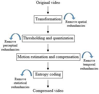
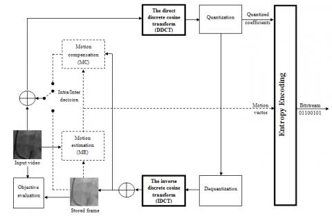
Figure 1 shows the direct general video compression scheme. The transformation is a linear, decorrelating and spatial transformable to cancel spatial redundancies. Allows information to be concentrated in a reduced number of coefficients. The choice of transformation is crucial; especially that it is principally responsible for the computational complexity. Usually is based on the use of the discrete cosine transformation (DCT) which generates matrices of 8 × 8 size. The thresholding and quantization process involves zeroing out the coefficients that fall below a preset threshold and quantizing the ones that remain. This reduces the perceivability of the blocks on the recreated frame, as the eye, although not very perceptive to subtleties, it is extremely sensitive to slight brightness variations in consistent zones. The entropy coding based on selection the of the best possible part of the lengthy series of zeros created by quantization and zigzag scanning; the zeros are coded first, followed by the non-zero value, thus reducing the statistical redundancies in the amount of information to be transmitted.
Figure 1. The general direct video compression scheme
Motion estimation and compensation has an important part in reducing temporal redundancy for the video coding systems. The current frames are predicted based on the previous or future frame known as references frames. Each frame is divided into macroblocks (MBs). The search for similar MBs is done between current and reference frames. The distance between the MB of the current frame and the most probable position of the MB of the reference frame represented by a motion vector (MV), this distance reflects the exact coordinates of the reference MB to be encoded.
In this work, the three-step search algorithm (TSS) [5] is used for mobility estimation of video sequences.
On the other hand, the medical video has been attracted attention of doctors to diagnose incurable diseases based on the various advanced technologies that we can find for example in hospitals, medical imaging centers, telediagnostic systems, etc. However, this rapid evolution can be led to a considerable increase in the medical data, which can cause saturation in transmission and storage systems. In order to avoid this problem, the standard coders were considered as a good solution to guarantee data integrity. However, the above norms are not significantly desired in the reduction of the volume of medical data. The only explanation is due to the transformation type.
To eliminate duplication, the most common coders are often based on the DCT. However, due to the quantization the DCT introduces annoying ringing artifact around the edges where are can be clearly visible for lower bitrate values. This can affect directly the quality of the medical diagnosis. Tsai et al. [6] have confirmed that DCT is not suitable for medical video compression.
The discrete wavelet transform has been used as an alternative to the DCT (DWT) which is known as the Mallat Pyramid scheme [7]. By using the DWT, smooth regions of the frame can be approximated very well with coarse approximation and detail wavelet coefficients. In the field of video coding, wavelets have been established as a very useful and effective tool. Ho et al. [8] have applied the DWT. The authors of this paper are used DWT in order to compress angiographic video rather than the DCT. This transform can drastically improve the compression efficiency. Haouam et al [9] have developed a method based on the active contour geometric model and a biorthogonal wavelet transform in order to get the best possible decrease in medical picture size without sacrificing quality. Hellel et al. [10] study the performance of video coding based on the second-generation wavelet transform.
In general, all complexes geometrics in the frame of video present the most important information which are represented with high-valued detail coefficients. Nonetheless, despite the prominence of wavelets in a variety of sectors, weaknesses were found in their use for detecting and representing curve-singularities. The cause is that its isotropic support is not optimal in the approximation of geometrical regularity. Theses basis are just dedicated to vertical, horizontal and diagonal directions and the other directions are killed. These characteristics are common to the majority known wavelet bases.
For this, the recognition of the geometric regularity with an adapted transform in frame representation is a major challenge to improve state-of-the-art video coding. Recent work shows that it is possible to define multi-scale representations known as the second generation of wavelets (or X-let families) more suitable for extracting intrinsic complex geometrical structures and devoted to enhancing the quality of videos. In particular, the ridgelet transform [11]. Unfortunately, the ridgelet transformation is only effective for characterizing straight contours rather than contours in an image, which are rarely straight. Candès and Donoho [12] have proposed a new representation in 2D space called curvelets, which provides a very elegant mathematical solution to adapt to the regularity of the images. The image support is first partitioned into squares of variable size. These squares are then decomposed by a discrete ridgelet analysis. The contourlet transform [13] was introduced by Do and Vetterli. The Laplacian pyramid with non-separable directional filter banks is applied on image. Then, a bank of directional filters is used on each level of the pyramid, which allows multi-directional analysis.
Recently, other adaptive approaches have been introduced, these approaches have greater flexibility than the non-adaptive approaches mentioned above. This is called adaptive geometric wavelets. For example, the bandelet transform were exploited for the first time by Le Pennec and Mallat [14] to detect all complex geometric in the image. The transform, known as the first-generation wavelet, is based on the wrapping of a wavelet basis to make horizontal (respectively vertical) directions along with the geometrical flow of frame gradients. However, the deformation leads to the appearance of the effect of boundary artifacts. In addition, the same authors have defined in the study of Peyré and Mallat [15] the second generation of bandelet where the 2D wavelet coefficients are reordered and followed by a 1D wavelet transform. The bandletization is used to remove the redundancy caused by wavelet and geometrical regularity. This type of transformation has known other applications not only on images but is also extended to video compression. In particular, Habchi et al. [16] have extended the bandelet basis to deal with medical videos. Beladgham et al. [17] have investigated the lifting bandelet transform for medical video compression.
The transform described above has proven its effectiveness in the precision encapsulation of complex geometries with non-redundant representation when it comes to objective measures and visual quality. However, this type of transformation is based on several complicated steps, among which we can mention in particular the quadtree decomposition where the difficulty of parameterization leads to a very high computation time and therefore a high algorithmic complexity. To overcome the above cited constraints, we present in this research, a novel multi-resolution decomposition that is relied on local adaptive transform prior to video coding.
The type of transformation where we would like to suggest is known by quincunx wavelet transform (QWT) where it is especially interesting, offer more freedom and can be adapted to the local properties of the of video.
The novelty in the proposed approach is the enhancement of visual quality of reconstructed medical video for lower bitrate across the combining of the QWT with SPIHT encoder (QWT+SPIHT).
The following is how this document is structured. In Section (2), the separable wavelet transform is described. The quincunx wavelet transform is discussed in Section (3). Section (4) briefly comments on the encoder processing. Sections (5) and (6) describe the suggested algorithm in depth, it includes the outcomes of the coding performance comparison.
Basically, each rectangular dyadic blocks of wavelet decomposition for n-level is called the subband coefficients. The finest level represents the highest frequency subbands (LH1, HL1, and HH1). On the contrary, the coarsest wavelet level represents the lowest frequency subbands (LLn, LHn, HLn, and HHn). Obviously, the edge and texture are shown for high frequency subband.
The specific features that characterize the wavelet such as the support size, the regularity, the symmetry, orthogonality, biorthogonality, etc., have made it required in many applications.
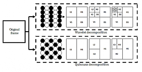
However, despite the huge success of wavelets, weaknesses were found in their use for contour detection. In order to overcome this problem, we suggest using the non-separable wavelet known as the quincunx wavelet transform (QWT) more adapted to the content of frames. Figure 2 illustrates this type of transform compared to the wavelet decomposition. Beladgham et al. [18] have proved the efficiency of this lattice in the enhancement of medical image compression.
The success of the QWT is due to its characteristics for example the value of the dilatation factor is $\sqrt{2}$ instead of 2 between two subsequent resolutions. Then, the only one wavelet is used instead of three wavelets.
The typical two-dimensional discrete wavelet transform's rectangular sampling matrix is substituted with the quincunx-sampling matrix, where the dilatation matrix is defined by:
$M=\left[\begin{array}{cc}1 & 1 \\ 1 & -1\end{array}\right]$ (1)
This dilatation matrix is the composition of rotation by $\frac{\pi}{4}$ with multiplication by $\sqrt{2}$. The quincunx lattice defined by a number of vectors d0, d1, …, dn. For this lattice the two defining vectors used are [19]: $d_0=\left(\begin{array}{l}1 \\ 1\end{array}\right)$ and $d_1=\left(\begin{array}{l}1 \\ -1\end{array}\right)$.
We note that $x[\vec{n}]$ with $\vec{n}=\left(n_1, n_2\right)^T \in Z^2$ is the discrete signal on the initial grid. Where, $D=D^T, D^{-1}=\frac{1}{2} D$ the quincunx decimated version of $x[\vec{n}]$, is defined as x[n]=x[Dn].
The two-dimensional Z-transform of $x[\vec{n}]$ is denoted by $X(\vec{z})=\sum \vec{n} \in \mathrm{Z}^2 x[\vec{n}] \vec{z}^{-\vec{n}}$, where $\vec{z}^{\vec{n}}=\vec{z}^n 1 \vec{z}^n 2$.
The continuous 2-D Fourier transform is then given by $X\left(e^{j \vec{\omega}}\right)=\Sigma \vec{n} \in Z^2 x[\vec{n}] e^{-j(\vec{\omega}, \vec{n})}$ with $\vec{\omega}=\left(\omega_1, \omega_2\right)$.
The discrete 2-D Fourier transform for $x[\vec{n}]$ given on an N × N grid (n1, n2=0, 1, …, N-1) by:
$X[\vec{k}]=\sum \vec{n} \in Z^{2} x[\vec{n}] e^{-j 2 \pi(\vec{k}, \vec{n}) / N}$, with (k1, k2=0, 1, …, N-1).
Figure 2. The third hierarchical wavelet decomposition and quincunx iterations
The quincunx sampled version of $x[\vec{n}]$ is given by:
$[\mathrm{x}]_{\downarrow M}[\overrightarrow{\mathrm{n}}]=\mathrm{x}[\mathrm{M} \overrightarrow{\mathrm{n}}]$ (2)
The down-sampling matrix M is such that M2=2I, where I is identity matrix. The relation in the Fourier domain is given by:
$[\mathrm{x}]_{\downarrow \mathrm{M}}[\overrightarrow{\mathrm{n}}] \leftrightarrow \frac{1}{2}\left[\mathrm{X}\left(\mathrm{e}^{\mathrm{j} \mathrm{M}^{-\mathrm{T}} \vec{\omega}}\right)+\mathrm{X}\left(\mathrm{e}^{\mathrm{j}\left(\mathrm{M}^{-\mathrm{T}} \vec{\omega}+\vec{\pi}\right)}\right)\right]$ (3)
where $\vec{\pi}=(\pi, \pi)$. The up-sampling is defined by:
$[\mathrm{x}] _{\uparrow M}[\vec{n}]=\left\{\begin{array}{cc}\mathrm{x}\left[\mathrm{M}^{-1}{\vec{n}}\right], & \text { when } \mathrm{n}_1+\mathrm{n}_2 \text { is even } \\ 0 & \text { elsewhere }\end{array}\right.$ (4)
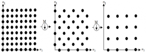
An example of the quincunx lattice sub-sampling for 2 iterations is shown in Figure 3.
Figure 3. The quincunx lattice sub-sampling for two iterations
Therefore, based to the previous formula of the down-sampling and up-sampling we get in the Fourier domain:
${ }^{[\mathrm{x}]_{\downarrow \mathrm{M} \uparrow {\mathrm{M}}}}{\quad}^{[\vec{\omega}]=}$$\frac{1}{2}\left[\mathrm{X}\left(\mathrm{e}^{\mathrm{j} \vec{\omega}}\right)+\mathrm{X}\left(\mathrm{e}^{\mathrm{j}(\vec{\omega}+\vec{\pi})}\right)\right]$ (5)
The quincunx filter bank structure consists of low-pass analysis filter H0, high-pass analysis filter H1, low-pass synthesis filter G0, high-pass synthesis filter G1, $\downarrow M$ down-samplers, $\uparrow M$ up-samplers and M is the quincunx decimation [20] where are typically applied in a recursive manner as shown in Figure 4.
The frequency responses of quincunx low-pass analysis filters are illustrated in Figure 5.
On the basis of Eq. (5) we define the conditions for a perfect reconstruction as follows:
$\left\{\begin{array}{l}\tilde{\mathrm{H}}(\overrightarrow{\mathrm{z}}) \mathrm{H}(\overrightarrow{\mathrm{z}})+\tilde{\mathrm{G}}(\overrightarrow{\mathrm{z}}) \mathrm{G}(\overrightarrow{\mathrm{z}})=2 \\ \tilde{\mathrm{H}}(-\overrightarrow{\mathrm{z}}) \mathrm{H}(\overrightarrow{\mathrm{z}})+\tilde{\mathrm{G}}(-\overrightarrow{\mathrm{z}}) \mathrm{G}(\overrightarrow{\mathrm{z}})=0\end{array}\right.$ (6)
Thus, the quincunx filter is given by the following formula:
$\mathrm{H}_\alpha(\mathrm{e} ^{j \vec{\omega}})=\frac{\sqrt{2}\left(2+\cos \omega_1+\cos \omega_2\right)\,\,^{\frac{\alpha}{2}}}{\sqrt{\left(2+\cos \omega_1+\cos \omega_2\right)\,^\alpha+\left(2-\cos \omega_1-\cos \omega_2\right)\,^\alpha}}$ (7)
α: the order parameter.
Figure 4. The quincunx filter bank structure for L-level. (a) The quincunx analysis side, (b) The quincunx synthesis side
Figure 5. The frequency responses of quincunx analysis filter
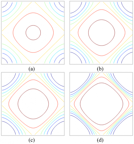
Figure 6. Contour plots of the low-pass filter: (a) $\alpha=\sqrt{2}$, (b) α=2.5, (c) α=π, (d) α=7
The contour plot of the scaling filter is shown in Figure 6. As showed by this figure, the shape of the contour are clearly centered, dilated around the centre and get smoother when the parameter order α increases. Therefore, the isotropy prove that no separable direction is given [21].
The orthogonal scaling function $\varphi_\alpha(\vec{x})$ that corresponds, is defined as
$\varphi_\alpha(\vec{x})=\sqrt{2} \sum_{\vec{k} \in Z^2} h_\alpha[\vec{k}] \varphi_\alpha(D \vec{x}-\vec{k})$ (8)
And the formula of the orthogonal quincunx wavelet $\varphi_\alpha(\vec{x})$ is:
$\psi_\alpha(\vec{x})=\sqrt{2} \sum_{\vec{k} \in Z^2} g_\alpha[\vec{k}] \varphi_\alpha(D \vec{x}-\vec{k})$ (9)
Several sub-band encoders, such as the embedded zero-tree wavelet (EZW) [22] and set partitioning in hierarchical trees (SPIHT) [23], have recently been suggested. One of the most efficient lossy image coding techniques is the SPIHT algorithm. The SPIHT's performance can be attributed to the outstanding establishment of wavelet coefficients into spatial orientation trees. Essentially, the major advantages of SPIHT are: (i) the ability to provide high picture quality; and (ii) the ease of storing and progressive transmissions of significant coefficient. The transformation, quantization, and entropy coding are the principal basis of the SPIHT.
Firstly, the DWT is applied to the image to generate the wavelet coefficients. The quantization and encoding are successively applied on the wavelet coefficients to produce the bitstream.
In a finer level, all coefficients represent the descendants but in the coarse level are named parent. The four coefficients in the next level are referred to as children (or offspring).
The SPIHT employs the following coordinate systems:
O(i, j): a set of coordinates for each node's offspring (i, j).
D(i, j): list of all node's descendants' coordinates (i, j).
L(i, j): collection of all descendants omitting the node's first four offspring (i, j). Where L(i, j)= D(i, j)- O(i, j).
The c(i, j) is called significant wavelet coefficient when c(i, j) ≥T (T=2n is threshold at resolution n); otherwise, it is called insignificant wavelet coefficient.
The significance is given by the following formula:
$S_n(T)=\left\{\begin{array}{l}1 \max _{(i, j) \in T}\{|C(i, j)|\} \geq 2^n \\ 0 \quad \text { otherwise }\end{array}\right.$ (10)
The SPIHT arranges information into three arranged lists: A list of inconsequential pixels (LIP), a list of salient pixels (LSP) and a list of insignificance sets (LIS) with their type A set if it represents D(i, j) and type B set if it represents L(i, j).
At the beginning, the LSP list of SPIHT is considered empty. In the coarsest level, the LIP list contains the all wavelet coefficients and its descendants are classified as type A in the list LIS. Respectively, the significant test is performed on the LIP, LIS and LSP list. In the sorting pass, the LSP list received the coded significant coefficients from the LIP list and LIS list. The LIS list's significant set is partitioned on the sets D(i, j) and L(i, j), which are progressively coded, and those that become significant are divided into subgroups. The following are the set partitioning rules:
If D(i, j) is significant, then it is partitioned into the four single-element sets L(i, j) with (k,l) $\in$O(i, j).
If L(i, j) is significant, then it is partitioned into four sets D(k,l) with (k,l) $\in$O(i, j).
We accept that at the highest and lowest pyramid levels, we have O(i, j)={(2i, 2j), (2i, 2j+1), (2i+1, 2j), (2i+1, 2j+1)}.
The end of the LIS list is filling with the coded sets L(i, j) and D(k,l).
Finally, the refinement pass is performed for each coefficient in LSP list. In the next resolution, the algorithm repeats the above procedure.
In this paper, the SPIHT is used to encode efficiently the produced quincunx coefficients.
The video is transferred from its source to its destination and it must be done in such a way that the quality of the video received is as close as possible to the quality of the video transmitted. For this, the high quality of the recovered medical video coding for low bitrate lies basically in the used transform. The QWT tries to achieve this goal.
The principle of our proposed algorithm is to reduce both types of information redundancy in the data as much as possible, without of course being obvious to the human eye. The video coding can be divided into two main modes: The intra mode and the inter mode.
In the proposed algorithm, the first and the last frame of medical video are coded in intra-coding mode, exploiting only spatial redundancy.
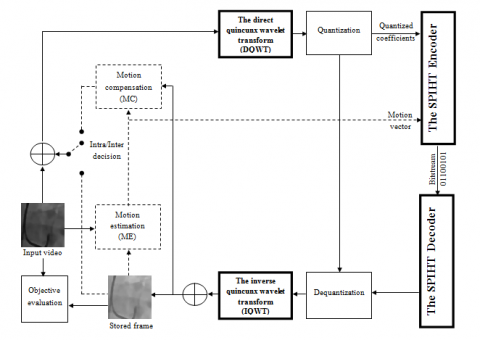
The QWT is used as an alternative transform to the DCT in H.264 standard as is shown in Figure 7 that allows the information to be concentrated in a reduced number of coefficients at the cost of a loss that must be controlled and qualified. For each frame, the order parameter and the number of iterations are fixed.
In order to control the bitrate, the quantization is applied. It is defined as the non-conservative compression step that reduces the amount of data contained in the transformed coefficients. The step consists on dividing each of the coefficients in a block by a quantization step and retaining only the entire part. The quantized coefficients are then rearranged and reordered in a one-dimensional vector by zigzag scanning to increase the efficiency of the next step (entropy coding). Finally, the quantized coefficients are entropy coded with SPIHT encoder and the generated bit-stream is stored or transmitted. At the same time, the encoder constructs the frame to be used as a reference for the next frame.
Once the first frame (frame I) is compressed, the predicted frames (frames P) are coded in inter-coding mode, exploiting only temporal redundancies.
Based on the motion estimation and compensation, the idea is to predict the current or future frames from already coded frames. Usually, video frames are divided into smaller blocks non-overlapping. That is, motion estimation and prediction is applied at a block level rather than on the whole frame. It consists in coding frame in relation to the previous frame. For each instance we take the current image (target) block by block and we look for identical blocks in the previous image.
(a)
(b)
Figure 7. The suggested quincunx lattice-based medical video compression block diagram. (a) H.264 standard, (b) Proposed algorithm
The closest block is utilized as the predictor block. The sum of absolute difference (SAD) criteria is used to evaluate the match between blocks. There are others criteria such as maximum cross-correlation (MCC), mean squared error (MSE) and sum of squared difference (SSD) [24].
The difference in position between the two blocks (target and reference) is called the motion vector (MV) obtained by motion estimation and then is coded as an intra frame. The location of the prediction block with respect to the current block is recorded through MV.
The search is limited by a search window with a search parameter P which represents the maximum value of the displacement to be estimated. Thereafter, a scan of the search area is performed until the search is converged. Convergence is defined by the minimization of the above criteria.
A comparison is made between the pixels of each macro-block position in the search area; this operation is called Block matching. This procedure is repeated until all the macro-blocks in the frame have been tested.
Finally, a vector field is then obtained. The block matching methods can be classified according to the scanning strategy in the search window or according to the size of the block and the size of the search window.
The search strategy and the dimensions of the search window and the block influence the computation cost. A large search window implies long calculations and a high risk of confusion of the searched block with a similar block. But as the size of the search window decreases, the estimated maximum displacement decreases. In the same way, when the blocks are large, the calculation cost is high, the spatial resolution is low and a block may contain pixels belonging to different objects. Conversely, a block that is too small may not contain enough discriminating information.
The latter is another problem arises. In this context, several search algorithms have been proposed in order to ensure a better estimation of motion between blocks. There are many methods of Block matching that seek to optimize the efficiency and speed of these algorithms. Motion estimation based on full search (FS) is always preferable in video compression, but the complexity of calculation and the time consumed in this technique is so immense, so the search and exploitation of other fast search algorithms is necessary.
In our algorithm, we have opted for the iterative algorithm named as Three Step Search (TSS) algorithm, which is one of the fast motion estimation methods proposed in the literature. The principle is to perform the search in several estimation steps. The point with the minimum SAD is used to calculate the new points to be tested.
Note that the pixel differences between two blocks are then transformed, quantized and entropy coded. These frames are reconstructed and stored for future motion estimation purposes.
The decoder works in the same way as the encoder, by executing the inverse actions of the encoder (entropy decoding, inverse quantization, inverse quincunx wavelet transform, etc.) to produce a decoded video sequence as close as possible to the initial sequence.
Finally, an objective evaluation is made between the original and reconstructed video.
The algorithm for enhanced compression of medical video is summarized in the following steps (Table 1):
The additional steps required for the proposed method are shown in bold.
Table 1. Proposed algorithm
|
I. For each frame of medical video. I.1 Apply Intra-prediction mode. I.1.1 Apply the direct quincunx wavelet transform (DQWT).
I.2 Apply Inter-prediction mode. I.2.1 Based on DQWT, performs motion estimation and compensation.
I.3 Based on QWT and SPIHT, apply the inverse operations to the steps (1.1) and (1.2). II. Use objective assessment parameters (PSNR, MSSIM and VIF). |
We investigate the performance of a suggested method based on lossy coding techniques at data rates ranging from 137.408 to 300.936 Kbps to encode set medical videos on grayscale. Each sample is quantized at eight bits per pixel (bpp).
The first and last frames are classified "I," and following frames are coded "P." All tested medical videos are taken from [25] where the variable characteristics are listed in Table 2.
Table 2. Characteristics of all standards tested videos
|
Medical Sequences |
The Number of Clips |
Clips Per Second (Hz) |
Width*Height |
Video Size |
|
Coronary angiography MRI brain Bladder cancer MRI-4chamber |
594 144 511 87 |
29.9700 29.9700 29.9700 29.9700 |
360*360 240*240 704*384 340*336 |
AVI AVI AVI AVI |
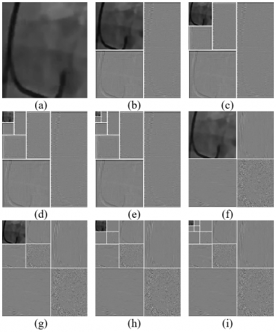
Figure 8. Quincunx and wavelet decomposition example of the tested medical frames (Coronary angiography): (a) Original frame, (b) QWT for 2 iterations, (c) QWT for 4 iterations, (d) QWT for 6 iterations, (e) QWT for 8 iterations, (f) DWT for 1 level, (g) DWT for 2, (h) DWT for 3 level, (i) DWT for 4 level
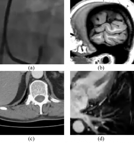
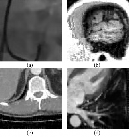
Coronary angiography is a process based on the use of a special contrast product and X-rays to see how blood flows via the heart's arteries.
Magnetic resonance imaging (MRI) creates precise images of the brain by using a high frequency sound wave.
Bladder cancer affects the tissues of the bladder abnormally.
MRI-4 chamber, characterized by its chambers of the heart (the atria and the ventricles).
In Figure 8, the coronary angiography video is dissected for the maximum number of iterations via performing a quincunx transformation, presenting all quincunx coefficients. The key observation of this study is the prospect of lowering rates while maintaining acceptable video quality.
The performance of the quincunx algorithm is proven with the biggest values of PSNR, MSSIM and VIF compared to the conventional algorithm for a low bitrate.
5.1 The peak signal-to-noise ratio (PSNR)
The PSNR is used to assess visual quality. The following is its definition [26]:
$P S N R=10 \log _{10}\left(\frac{\left(2^n-1\right)^2}{M S E}\right)$ (11)
where, (2n-1) is the signal’s dynamic. In the typical situation of a picture, A pixel's components are saved on n=8 bits/pixel. MSE denotes the average squared distortion over image sequences, Specifically, the original frame f(i,j) and the recovered frame fr(i,j) of size M × N are provided by:
$M S E=\frac{1}{M N} \sum_{i=1}^M \sum_{j=1}^N\left(f(i, j)-f_r(i, j)\right)^2$ (12)
5.2 The mean SSIM (MSSIM)
Three major aspects are introduced by the SSIM index: luminance l, contrast c, and structure s [27].
$\operatorname{SSIM}\left(f, f_r\right)=l\left(f, f_r\right) c\left(f, f_r\right) s\left(f, f_r\right)$ (13)
The following equation defines the luminance comparison function l:
$l(x, y)=\frac{2 M_x M_y+C_1}{M_x^2+M_y^2+C_1}$ (14)
where, Mx and My represent the signal's average intensity x and y defined by $M_x=\frac{1}{N} \sum_{i=1}^N x_i \quad$ and $\quad M_y=\frac{1}{N} \sum_{i=1}^N y_i$ respectively. $C_i=K_i^2 D^2, i=1,2$ and Ki is a constant, such as Ki<<1 and D is the dynamic range. The following is the syntax for the contrast comparison function c:
$c(x, y)=\frac{2 \sigma_x \sigma_y+C_2}{\sigma_x^2+\sigma_y^2+C_2}$ (15)
where $\sigma_x=\left(\frac{1}{N-1} \sum_{i=1}^N\left(x_i^2-\left(M_x\right)^2\right)\right)^{1 / 2}$.
The function s is a framework reference formulated as below:
$s(x, y)=\frac{\sigma_{x y}+C_3}{\sigma_x \sigma_y+C_3}=\frac{\operatorname{cov}(x, y)+C_3}{\sigma_x \sigma_y+C_3}$ (16)
$C_3=\frac{C_2}{2}$ and cov(x,y) = Mxy-MxMy with $M_{x y}=\frac{1}{N-1} \sum_{i=1}^N x_i y_i$.
As a result, the structural similarity (SSIM) index is expressed explicitly:
$\operatorname{SSIM}(x, y)=\frac{\left(2 M_x M_y+C_1\right)\left(2 \sigma_{x y}+C_2\right)}{\left(M_x^2+M_y^2+C_1\right)\left(\sigma_x^2 \sigma_y^2+C_2\right)}$ (17)
where $\sigma_{x y}=\left(\frac{1}{N-1} \sum_{i=1}^N\left(\left(x_i y_i\right)^2-\left(M_{x y}\right)^2\right)\right)^{1 / 2}$.
The average value of SSIM is needed as Mean SSIM (MSSIM):
$\operatorname{MSSIM}\left(f, f_r\right)=\frac{1}{L} \sum_{i=1}^L \operatorname{SSIM}\left(f_i, f_{r i}\right)$ (18)
where,
fi: the original frame.
fri: the recovered frame.
L: the total of local windows number in frame.
5.3 The visual information fidelity (VIF)
Sheikh and Bovik [28] introduced the VIF for assessing picture quality. The VIF measure takes values between 0 and 1, where 1 means perfect quality and is given by:
The VIF metric is given a number between 0 and 1, with 1 indicating ideal quality:
$V I F=\frac{\sum_j I\left(C^j ; F^j / s^j\right)}{\sum_j I\left(C^j ; E^j / s^j\right)}$ (19)
where, I(X;Y/Z) the conditional mutual information between X and Y, given z,
C the arbitrary selection from one of the original image's channels,
sj is a realization of Sj for a particular reference image. The realization sj could be thought of as “model parameters” for the associated reference image and the index j goes over all of the deconstructed image's sub-bands, E the visual signal, and F the test image.
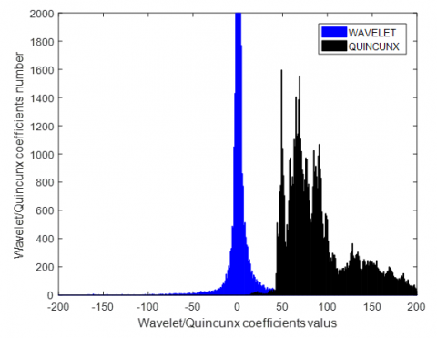
Figure 9 illustrates a comparison between the histograms of wavelet and quincunx coefficients number. Obviously, the larger coefficients values of complex geometric are shown for quincunx coefficients. This confirms that quincunx is a suitable transform for medical video coding. The biggest number of zero coefficients confirms that the wavelets killed all directions that are not horizontal, vertical and diagonal.
Figure 9. Histograms of quincunx and wavelet coefficients number
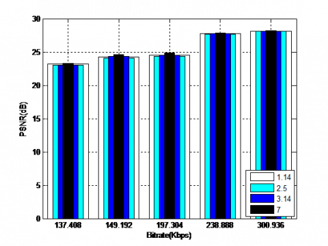
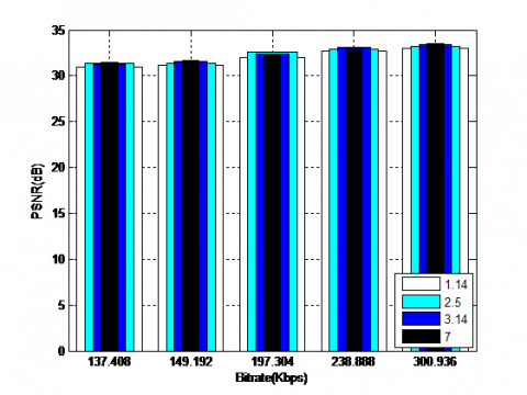
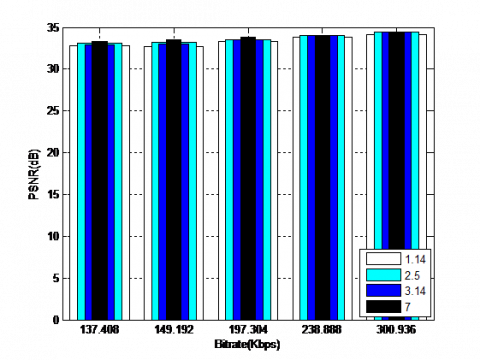
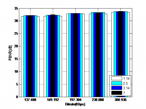
Figure 10 depict the obtained results for the coding Coronary angiography video using the QWT+SPIHT algorithm for different values of α (for 1.14, 2.5, 3.14 and 7) and levels (for 3, 4, 5 and 6) respectively. The results illustrate how the PSNR (dB) varies according to the level and α. The best values of objective parameters are for larger values of α (equal to 7) and decomposition level (equal to 5). It should be noted that the increase in α values over 7 can lead to the appearance of the ringing artefacts around the edges.
(a) Decomposition level (equal to 3)
(b) Decomposition level (equal to 4)
(c) Decomposition level (equal to 5)
(d) Decomposition level (equal to 6)
Figure 10. Coding results using the QWT+SPIHT algorithm for different values of order parameter and levels
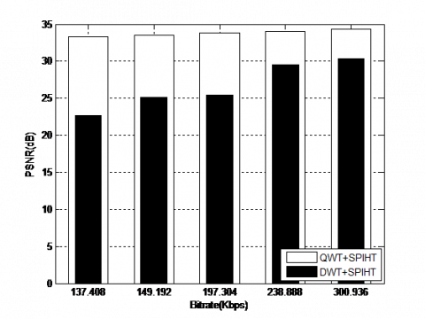
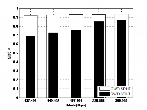
The suggested algorithm's efficiency has been demonstrated through comparison with the DWT+SPIHT algorithm based on the wavelet basis. Figure 11 shows the obtained results for the fixed values of α=7 and level = 5.
Clearly, it can be seen that the QWT+SPIHT algorithm applied on the Coronary angiography video is outperform compared to the DWT+SPIHT. This is proved with the visual quality of the reconstructed video, where the objective parameters of the proposed algorithm are higher values at all bitrates. The gain in PSNR between QWT+SPIHT and algorithms DWT+SPIHT exceeds 4dB for all bitrates [137.408-300.938] Kbps. For example, the gain reaches 4.0225 dB, 4.4227dB, 8.3966dB, 8.3413dB and 10.6053dB at 300.936 Kbps, 238.888 Kbps, 197.304 Kbps, 149.192 Kbps, 137.408 Kbps, respectively.
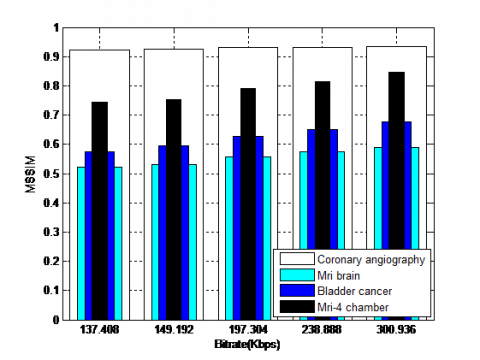
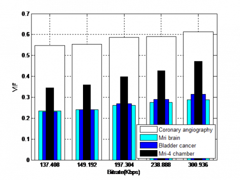
On the other hand, the QWT+SPIHT algorithm is not only tested on the Coronary angiography but is tested on the set of videos such as Mri brain, Bladder cancer and Mri-4chamber (Figure 12). The obtained results show that QWT+SPIHT are significant and considerable over a wide range of bitrates for all tested videos. For example, at 137.408 Kbps, PSNR reaches 34.38 dB for Coronary angiography, 17.72 dB for Mri brain, 22.77dB for Bladder cancer, and 27.94 dB for Mri-4chamber.
Obviously, in terms of the visual quality, the proposed algorithm confirms its improvement on the Coronary angiography video as shown in Figure 13 and Figure 14. Also, it is very important to note that the values of the objective parameters depend on the video type and the bitrate value.
(a) PSNR
(b) MSSIM
(c) VIF
Figure 11. Coding results using the DWT+SPIHT and QWT+SPIHT algorithms for the best values of order parameter and levels
The all algorithms were established using MATLAB R2010a on an Intel(R) Core (TM): 3-5005U CPU@2.00GHz.
Based on the results obtained above, we can say that the QWT+SPIHT algorithm with the adapted decomposition level and higher-order parameter α is more efficient for the detection of all complex geometries and the improvement of the visual quality of the medical videos.
In the last part, we make a comparison between the efficiency of the suggested algorithm QWT+SPIHT and the H.264 standard [29] for the first ten frames of the Coronary angiography video.
Figure 12. Original medical video: (a) Coronary angiography, (b) Mri brain, (c) Bladder cancer, (d) Mri-4chamber
(a)
(b)
(c)
Figure 13. (a) PSNR, (b) MSSIM and (c) VIF results based on the QWT+SPIHT algorithm tested for a set of medical videos
Figure 14. Visual coding results using the QWT+SPIHT algorithm at 300.936Kbps for (a) Coronary angiography, (b) MRI brain, (c) Bladder cancer, (d) MRI-4chamber
From Table 3 we can show significantly the outperform of QWT+SPIHT over H.264 for all bitrate values in term of objectives parameters and the encoding/decoding time. This means that QWT+SPIHT algorithm offer significantly higher coding quality for local lower bitrates. For example, at 137.408 Kbps the gain in PSNR reaches 16.3057dB. This achieves the desired goal.
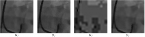
The quality of reconstructed frames using DWT+SPIHT, H.264 and QWT+SPIHT are shown in Figure 15. The proposed QWT+SPIHT algorithm spends a short time and demonstrated its effectiveness in terms of computational time (include coding/decoding) compared to the H.264 standard for each bitrate values, as shown in the above table. Therefore, it is possible to help the doctors in the accurately detecting certain regions of specific importance (ROI) compared to the other regions. Thus, the QWT+SPIHT is expected to be effective for medical video compression applications.
Figure 15. Visual coding results for (a) Original Coronary angiography frames using (b) H.264, (c) DWT+SPIHT, (d) QWT+SPIHT at 300.936 Kbps
Table 3. PSNR, MSSIM, VIF and coding/decoding time results based on comparison between the H.264 standard and QWT+SPIHT algorithm for the first ten frame of coronary angiography video
|
Bitrate (Kbps) |
H.264 |
QWT+SPIHT |
Gain (dB) |
||||||
|
PSNR (dB) |
MSSIM |
VIF |
Coding/ decoding time |
PSNR (dB) |
MSSIM |
VIF |
Coding/ decoding time |
||
|
300.936 |
37.4098 |
0.9672 |
0.7285 |
39,152186 |
34.3843 |
0.9345 |
0.6127 |
6,70346 |
-3,0255 |
|
238.888 |
33.7786 |
0.9464 |
0.6230 |
38,956255 |
33.9797 |
0.9319 |
0.5904 |
6,593523 |
0,2011 |
|
197.304 |
30.7203 |
0.9255 |
0.5334 |
39,187627 |
33.7924 |
0.9306 |
0.5873 |
6,689195 |
3,0721 |
|
149.192 |
20.1945 |
0.8623 |
0.2830 |
39,129597 |
33.5125 |
0.9246 |
0.5544 |
6,610732 |
13,318 |
|
137.408 |
16.9791 |
0.8402 |
0.2141 |
39,09806 |
33.2848 |
0.9224 |
0.5477 |
7,846785 |
16,3057 |
As a future study, more contributions can be made in coordination with various current studies such as Li and Chai [30], Zhao [31], etc.
In this paper, a low bitrate medical video coding system based on the quincunx wavelet and the SPIHT algorithm is proposed, namely QWT+SPIHT has been proposed. The redundant data are reduced drastically, and the quality of the video is enhanced without altering the content of the video. The quincunx wavelet provides additional flexibility and can be better tailored to frame content. All created quincunx coefficients are encoded using the SPIHT. The efficiency of the QWT+SPIHT is tested on the set of medicals videos. The results obtained on different bitrate show significant improvement compared to the conventional algorithms, especially for low bitrate values. The recovered video presents a subjective quality that is satisfactory for the medical field. Furthermore, our proposed algorithm spends a short time on coding and decoding operations.
The authors extend their appreciation to the Deanship of Scientific Research at King Khalid University for funding this work through the large groups research program under grant number R.G.P. 2/112/43.
[1] Camastra, F., Vinciarelli, A. (2015). Image and video acquisition, representation and storage. In: Machine Learning for Audio, Image and Video Analysis. Advanced Information and Knowledge Processing. Springer, London. https://doi.org/10.1007/978-1-84800-007-0_3
[2] Challapali, K., Nocture, G. (1996). Video compression for digital television applications. Philips Journal of Research, 50(1-2): 5-19. https://doi.org/10.1016/0165-5817(96)81298-8
[3] Alzahir, S. (2011). A fast lossless compression algorithm for Arabic textual images. 2011 IEEE International Conference on Signal and Image Processing Applications (ICSIPA), pp. 595-598. https://doi.org/10.1109/ICSIPA.2011.6144069
[4] Chai, D., Bouzerdoum, A. (2001). JPEG2000 image compression: An overview. The Seventh Australian and New Zealand Intelligent Information Systems Conference, pp. 237-241. https://doi.org/10.1109/ANZIIS.2001.974083
[5] Lu, J., Liou, M.L. (1997). A simple and efficient search algorithm for block-matching motion estimation. IEEE Transactions on Circuits and Systems for Video Technology, 7(2): 429-433. https://doi.org/10.1109/76.564122
[6] Tsai, M.J., Villasenor, J.D., Ho, B.K.T. (1994). Coronary angiogram video compression. Proceedings of 1994 IEEE Nuclear Science Symposium - NSS'94, pp. 1847-1851. https://doi.org/10.1109/NSSMIC.1994.474705
[7] Mallat, S.G. (1989). A theory for multiresolution signal decomposition: the wavelet representation. IEEE Transaction on Pattern Analysis and Machine Intelligence, 11(7): 674-693. https://doi.org/10.1109/34.192463
[8] Ho, B.K.T., Tsai, M.J., Wei, J., Ma, M., Saipetch, P. (1996). Video compression of coronary angiograms based on discrete wavelet transform with block classification. IEEE Transactions on Medical Imaging, 15(6): 814-823. https://doi.org/10.1109/42.544499
[9] Haouam, I., Beladgham, M., Bendjillali, R.I. (2018). MRI image compression using level set method and biorthogonal CDF wavelet based on lifting scheme. 2018 International Conference on Signal, Image, Vision and their Applications (SIVA), pp. 1-7. https://doi.org/10.1109/SIVA.2018.8661068
[10] Hellel, O., Beladgham, M., Lakhdar, A.M. (2019). Study of performance of a ‘second-generation wavelet video encoder with a scalable rate’. IET Image Processing, 13(4): 698-706. https://doi.org/10.1049/iet-ipr.2018.5345
[11] Do, M.N., Vetterli, M. (2000). Orthonormal finite ridgelet transform for image compression. Proceedings 2000 International Conference on Image Processing (Cat. No.00CH37101), pp. 367-370. https://doi.org/10.1109/ICIP.2000.899394
[12] Candes, E.J., Donoho, D.L. (2000). Curvelets, multiresolution representation, and scaling laws. Wavelet Appl. Signal Image Process. VIII, 2000, 4119. https://doi.org/10.1117/12.408568
[13] Do, M.N., Vetterli, M. (2005). The contourlet transform: An efficient directional multiresolution image representation. IEEE Transactions on Image Processing, 14(12): 2091-2106. https://doi.org/10.1109/TIP.2005.859376
[14] Le Pennec, E., Mallat, S. (2005). Sparse geometric image representations with bandelets. IEEE Transactions on Image Processing, 14(4): 423-438. https://doi.org/10.1109/TIP.2005.843753
[15] Peyré, G., Mallat, S. (2005). Surface compression with geometric bandelets. ACM Transactions on Graphics, 24(3): 601-608. https://doi.org/10.1145/1073204.1073236
[16] Habchi, Y., Ouahabi, A., Beladgham, M., Taleb-Ahmed, A. (2016). Towards a new standard in medical video compression. IECON 2016 - 42nd Annual Conference of the IEEE Industrial Electronics Society, pp. 1061-1066. https://doi.org/10.1109/IECON.2016.7793301
[17] Beladgham, M., Habchi, Y., Ben aissa, M., Taleb-Ahmed, A. (2019). Medical video compression using bandelet based on lifting scheme and SPIHT coding: In search of high visual quality. Informatics in Medicine Unlocked, 17: 100244. https://doi.org/10.1016/j.imu.2019.100244
[18] Beladgham, M., Bessaid, A., Taleb-Ahmed, A., Boucli Hacene, I. (2012). Medical image compression using quincunx wavelets and SPIHT coding. Journal of Electrical Engineering and Technology, 7(2): 264-272. https://doi.org/10.5370/JEET.2012.7.2.264
[19] Han, B., Jia, R.Q. (2000). Quincunx fundamental refinable functions and quincunx biorthogonal wavelets. Mathematics of Computation, 71(237): 165-197.
[20] Nagare, M.B., Patil, B.D., Holambe, R.S. (2017). Design of two-dimensional quincunx FIR filter banks using eigen filter approach. 2016 International Conference on Signal and Information Processing (IConSIP), pp. 1-5. https://doi.org/10.1109/ICONSIP.2016.7857452
[21] Yin, R. (2015). Construction of orthonormal directional wavelets based on quincunx dilation subsampling. 2015 International Conference on Sampling Theory and Applications (SampTA), pp. 292-296. https://doi.org/10.1109/SAMPTA.2015.7148899
[22] Shapiro, J.M. (1993). Embedded image coding using zerotrees of wavelet coefficients. IEEE Transactions on Signal Processing, 41(12): 3445-3462. https://doi.org/10.1109/78.258085
[23] Said, A., Pearlman, W.A. (1996). A new, fast, and efficient image codec based on set partitioning in hierarchical trees. IEEE Transactions on Circuits and Systems for Video Technology, 6(3): 243-250. https://doi.org/10.1109/76.499834
[24] Vanne, J., Aho, E., Hamalainen, T.D., Kuusilinna, K. (2016). A high-performance sum of absolute difference implementation for motion estimation. IEEE Transactions on Circuits and Systems for Video Technology, 16(7): 876-883. https://doi.org/10.1109/TCSVT.2006.877150
[25] https://medtube.net/, accessed on December 12 2016.
[26] Zhu, K., Asari, V., Saupe, D. (2013). No-reference quality assessment of H. 264/AVC encoded video based on natural scene features. ‘Mobile Multimedia/Image Processing, Security, and Applications 2013’ (International Society for Optics and Photonics, 2013).
[27] Wang, S., Gu, K., Zeng, K., Wang, Z., Lin, W. (2018). Objective quality assessment and perceptual compression of screen content images. IEEE Computer Graphics and Applications, 38(1): 47-58. https://doi.org/10.1109/MCG.2016.46
[28] Sheikh, H.R., Bovik, A.C. (2006). Image information and visual quality. IEEE Transactions on Image Processing, 15(2): 430-444. https://doi.org/10.1109/TIP.2005.859378
[29] ISO/IEC 14496-10 and ITU-T Rec. H.264, Advanced Video Coding, 2003.
[30] Li, S.L., Chai, H.Q. (2021). Recognition of teaching features and behaviors in online open courses based on image processing. Traitement du Signal, 38(1): 155-164. https://doi.org/10.18280/ts.380116
[31] Zhao, H. (2022). Image target recognition based on multiregional features under hybrid attention mechanism. Traitement du Signal, 39(2): 595-601. https://doi.org/10.18280/ts.390221