Mohamed Brahimi | Mustafa Inc* | Hijaz Ahmad | Younes Menni | Giulio Lorenzini
© 2022 IIETA. This article is published by IIETA and is licensed under the CC BY 4.0 license (http://creativecommons.org/licenses/by/4.0/).
OPEN ACCESS
In this article, an algorithm with global constraints known as hybrid non-linear programming with particle swarm enhancement is available for improving the circular antenna array (CAA) radiation characteristics. The suggested method combines the optimization of excitation currents with the array's element spacing to create the correct beam patterns. In this context, adaptive particle optimization (APSO) and basic particle swarm optimization (BPSO) algorithms are applied with the previous method to the (8,12,20) elements to tune the array's amplitude and positioning to achieve a radiation profile with reduced SLL. The simulated results show that the recommended strategy provides the greatest decrease in side lobe levels and directivity.
non-linear programming, stochastic optimization, mathematical modeling, circular antenna elements, side lobe level, particle swarm enhancement
A group of investigators have expressed an interest in the topic of synthesis of desired radiation patterns for antenna elements in recent years. Due to their utility in wireless communications, radar systems, satellite communications, military, and mobile communications, it has been studied. Excitations' amplitudes and phases, or array positions, can be controlled to synthesize arrays. According to studies published in the studies [1-3], circular array antennas are more effective than linear and planar arrays.
Circular antenna arrays can cover any area with their radiation pattern [4]. Furthermore, the CAA’ main lobe can be oriented in any required direction [5]. Several factors, including the CAA's excitation current, influence the beam patterns [6]. As a result, synthesis of beam patterns and maximum SLL reduction of the CAA are especially relevant for the application of the CAA to different communication applications.
Several approaches to antenna array synthesis have been published in the research literature to solve the array synthesis problem. Array synthesis is a multimodal problem, however, and they are often unable to handle it. Furthermore, because they generally based on the initial solution, they are frequently trapped in the local best solution. In recent years, many evolutionary algorithms and nature-based metaheuristics have been studied to overcome the above-mentioned problems with traditional numerical techniques. Multi-objective evolutionary computing techniques are known to solve problems with multiple objectives without regard to the initial solution [7].
Several heuristic search algorithms have been employed to design conventional CAAs, in addition to particle swarm optimization (PSO) [8-10], genetic algorithm (GA) [11, 12], simulated annealing (SA) [13, 14], biogeography-based optimization (BBO) [15], firefly algorithm (FFA) [16], cat swarm optimization (CSO) [17], moth flame optimization (MFO) [18], and social spider algorithm (SSA) [19].
Like other evolutionary algorithms, these methods suffer from problems such as prematurity, limited searching scope, and convergence to local extrema. Several evolutionary techniques have been developed and effectively implemented to overcome these problems, including CAA array pattern synthesis for maximum SLL suppression and null control under beam width constraints.
In this paper, non-linear programming technique has been employed to enhance famous version of particle swarm.
Despite many works on the subject, the PSO over NLCOP continues to be of interest [20-23]. NLCOP with equality constraints is studied by Luo et al. [24], which removes constraints by partitioning mixed variables.
Other studies with different models have been recently listed such as Thazeen et al. [25], Mandal et al. [26], Kennedy and Eberhart [27], Shi [28], Eberhart and Shi [29], Lakhlef et al. [30], Parsopoulos and Vrahatis [31], Hu et al. [32], Parsopoulos and Vrahatis [33] and Tuhvatullin et al. [34]. Mathematical models with different algorithms have been used in these studies.
In adaptive particle swarm optimization (APSO), the parameters of algorithms like inertia weight and acceleration coefficients are dynamically adjust during the evolution process.
In CAA synthesis, three types of simulation were used: amplitude only, position only, and amplitude–position.
Three different algorithms were used to explore the position-only technique: non-linear programming with particle swarm optimization (NP-PSO), adaptive particle swarm optimization (APSO), and basic particle swarm optimization (BPSO). For the purpose of minimizing the maximum SLL and maximizing the directivity, these methods were used to evaluate the best positions for the parts around the circle. Based on the simulation findings, these strategies may be able to suppress the SLL. While other radiation parameters are being controlled Furthermore, amplitude-only approaches employ a nonuniform current distribution while element placements are fixed and stay constant. By using excitation amplitudes, the radiation pattern of CAA may be controlled, as well as lowering the SLL and achieving a significant gain.
The work is divided into eight sections, the second of which contains the array factor and the fitness function formulation. Sections 3, 4, and 5 discussed the characteristics of the methods used in the work, including the array efficiency issue's application. Following that, in Section 6, all of the results are presented, along with extensive discussion, Section 7 provides a comparative analysis, while Section 8 provides broad findings.
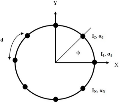
The geometry of the CAA is seen in Figure 1.
Figure 1. The circular antenna array geometry
A concentric ring of radius r is analyzed in the x–y plane, with θ and φ indicating the angles of elevation and azimuth, respectively.
$A F(\phi)=\sum_{n=1}^{N_{E}} I_{n} e^{j\left[\beta r \cos \left(\phi-\phi_{n}+\alpha_{n}\right]\right.}$ (1)
With:
$I_{n}$: the amplitude of the excitation current;
$\alpha_{n}$: the phase of the excitation current'; and,
$\varphi_{n}$: the nth element’ angular position on x-y plane.
$\phi_{n}=\frac{2 \pi(n-1)}{N_{E}}$ (2)
The spacing angle is controlled by the number of antennae components and the spacing angle, the wave number β can be written as:
$\beta \,r=\frac{2\pi \,r}{\lambda }=\sum\limits_{i=1}^{{{N}_{E}}}{{{d}_{i}}={{N}_{E}}d}$ (3)
Maxima of the array factor AF dictate the orientation of the main beam $\left(\varphi_{0}\right)$, which can be adjusted by the moderate adjusting variable $\alpha_{n}$ as follows:
$\alpha_{n}=-\beta r \cos \left(\phi_{0}-\phi_{n}\right)$ (4)
Therefore, the AF may be defined in terms of the intended primary lobe orientation as:
$AF\left( \varphi \right)=\sum\limits_{n=1}^{{{N}_{E}}}{{{I}_{n}}{{e}^{j\left[ \beta \,r\left( \cos \left( \varphi -{{\varphi }_{n}} \right)-\cos \left( {{\varphi }_{0}}-{{\varphi }_{n}} \right) \right)+\psi \right]}}}$ (5)
where, $I_{n}$ and $\psi$ are the estimated adjusted amplitude and phase for controlling the figure of merit of the circular antenna array.
The regulated amplitude and phase range vary from [0, 1] and [180°, 180°] when the amplitude is normalized to its greatest value.
The primary goal of this study is to increase directivity and minimize SLL by getting the required major lobe orientation.
The objective may be divided into three parts to obtain the same result:
$O F_{S L L}=\frac{\left|A F\left(\phi_{S L L} \quad , \quad \vec{I}, \quad \vec{\beta}, \quad \phi_{0}\right)\right|}{\left|A F\left(\phi_{\max } \quad , \quad \vec{I}, \quad \vec{\beta}, \quad \phi_{0}\right)\right|}$ (6)
$O F_{D}=\frac{1}{\operatorname{dir}\left(\phi_{0}, \vec{I}, \vec{\beta}\right)}$ (7)
$O F_{M I}=\left|\phi_{0}-\phi_{d e s}\right|$ (8)
The three objectives may be met by decreasing the entire optimization approach for CAA design (OFCAA).
$O{{F}_{CAA}}=O{{F}_{SLL}}+O{{F}_{D}}+O{{F}_{ML}}$ (9)
The $O F_{S L L}$ is the fitness function aimed towards lowering SLL, where $\varphi_{S L L}$ denotes the greatest side lobe angle. Besides, the directivity at the main lobe direction $\varphi_{S L L}$ should be maximized. The same result may be accomplished by putting this in the desired function's denominator $O F_{D}$. In the third part $\left(O F_{M L}\right)$ of the objective function, the main lobe is aligned with the desired direction $\left(\varphi_{\text {des }}\right)$. As a result, achieving these three figures of merit will be accomplished by minimizing the overall goal function [3].
When compared to standard optimization methods, PSO is an efficient, Adaptive population-based probabilistic heuristic search approach with implicit parallelism that can manage non-differential objective functions with ease [26]. In contrast to GA, Simulated Annealing, and other optimization methods, basic PSO is less sensitive to becoming trapped in local optima. Kennedy, Eberhart, and Shi [27, 28] proposed a standard PSO idea based on a swarm of birds' behavior. The core PSO was built by simulating three-dimensional bird flocking. A certain objective function is maximized by bird flocking. So far, each agent is aware of its best worth (pbest). This material, according to each agent, represents their own experiences. Furthermore, in the group (gbest) each agent is aware of the best value among pbests so far.
Consequently, each agent focuses on changing its position depending on the following information:
The particle speeds are numerically modified using such a following equation:
$\begin{align} & V_{i}^{k+1}=\omega \times V_{i}^{k}+{{C}_{1}}\times {{R}_{1}}\times \left( p{{b}_{i}}-S_{i}^{k} \right) \\ & +{{C}_{2}}\times {{R}_{2}}\times \left( g{{b}_{i}}-S_{i}^{k} \right) \\\end{align}$ (10)
where:
$V_{i}^{k}$: is agent i's velocity at iteration k
$\omega$: is the weight of inertia
$C_{i}$:is the rate of acceleration
$R_{i}$: is a number chosen at random from 0 to 1.
$S_{i}^{k}$: is agent i's current location at iteration k
$p b_{i}$: pbest of agent i
$g b_{i}$: the gbest of the group
In the solution space, the following equation can be changed to determine the searching point:
$S_{i}^{k+1}=S_{i}^{k}+V_{i}^{k+1}$ (11)
The first item in (10) is the agent's prior velocity. The third and second items modify the agent's velocity. The agent will continue 'flying' in the same direction in the absence of the second and third components, until it hits the border. In other words, it represents an inertia that explores new areas.
The inertial mass and acceleration coefficient are neither given a constant value in this section, nor assigned to a time-varying function with linear decay [29]. In Eqns. (12)-(13), the minimization problem's fitness function is described because of the finest available locally (pbest) and global best (gbest) values. (pbesti) average denotes the mean of all the best personal values of this generation.
${{\omega }_{i}}=\left( 1.1-\frac{gb}{{{\left( p{{b}_{i}} \right)}_{av}}} \right)$ (12)
${{C}_{i}}=\left( 1+\frac{gb}{\left( p{{b}_{i}} \right)} \right)$ (13)
In this work, the improved PSO approach will be used to a Non-Linear Constrained Optimization Problem (NLCOP). Even though a considerable number of works have been done on this subject, the PSO over NLCOP remains of interest [20, 31-33]. Luo et al. [24] utilize NLCOP with equality constraints, which are removed using mixed variable partitioning.
The penalty approach, the barrier technique, the Lagrangian factor, and the sub gradient approach are all examples of methods, and other strategies are available for converting NLP with constraints to NLP without constraints. In this situation, we employ the Barrier strategy to convert the problem to NLP without restrictions, and then we use the Improved PSO method to find the solution.
In the original equation, the PSO approach applied here consists of three updates. Let's have a look at the formula for updating the velocity and location of the PSO, which is derived from Eq. (10),
$V_{i}^{k+1}=\chi \left\{ \begin{align} & V_{i}^{k}+{{C}_{1}}\times {{R}_{1}}\times \left( p{{b}_{i}}-S_{i}^{k} \right) \\ & +{{C}_{2}}\times {{R}_{2}}\times \left( g{{b}_{i}}-S_{i}^{k} \right) \\\end{align} \right\}$ (14)
where $\chi$, is a weighing factor. Or,
$\begin{align} & V_{i}^{k+1}=\chi \times V_{i}^{k}+\chi \times {{C}_{1}}\times {{R}_{1}}\times \left( p{{b}_{i}}-S_{i}^{k} \right) \\ & +\chi \times {{C}_{2}}\times {{R}_{2}}\times \left( g{{b}_{i}}-S_{i}^{k} \right) \\\end{align}$ (15)
Or
$\begin{align} & V_{i}^{k+1}=\chi \times V_{i}^{k}+{{k}_{1}}\times {{R}_{1}}\times \left( p{{b}_{i}}-S_{i}^{k} \right) \\ & +{{k}_{2}}\times {{R}_{2}}\times \left( g{{b}_{i}}-S_{i}^{k} \right) \\\end{align}$ (16)
The random number $r_{2}$ is taken to be 1-r $r_{2}$, in our computational experiment, $\chi$ is assumed to be zero, and the second and third terms stay unaltered. ( $k_{1}$ and $k_{2}$ stay unaltered), This leads in a velocity that is independent of the velocity in the previous iteration in each iteration. It merely makes use of the impact of $p b_{i}$ and $g b_{i}$ obtained previously. As a result, the velocity update formula is
$\begin{align} & V_{i}^{k+1}={{k}_{1}}\times {{R}_{1}}\times \left( p{{b}_{i}}-S_{i}^{k} \right) \\ & +{{k}_{2}}\times \left( 1-{{R}_{1}} \right)\times \left( g{{b}_{i}}-S_{i}^{k} \right) \\\end{align}$ (17)
In our experiment, we used the constant $k_{1}$ and $k_{2}$ as 2 each. $\chi=0$ for 1 st term, and $R_{2}=1-R_{1}$ (where $k_{1}=\chi C_{1}$ and $k_{2}=\chi C_{2}$).
PSO's position update is provided by Eq. (11).
The circular array antenna was created with the goal of suppressing SLL. In this study, we look at three distinct techniques for handling the beam pattern optimization problem: 8-element CAA, 12-element CAA, and 20-element CAA. Three cases are presented in the simulation-based experimentation. Amplitude-only, angular position-only, and amplitude–angular position synthesis techniques are all examples of synthesis techniques. To find the best solution, each algorithm was run on a 2.30 GHz Intel Core (TM) 2348M processor with 4-GB RAM in MATLAB 2013b.
6.1 Circular antenna array synthesis using amplitude only technique
6.1.1 Synthesis of 8‑elements using amplitude only technique
To deliver the optimal radiation sample for CAA, the BPSO, APSO, and NP-PSO algorithms are applied to synthesize CAA using amplitude only technique.
Table 1 show the best results obtained by using the three algorithms for 8 elements CAA. The present excitation weights, inter-element spacing, and maximum SLL are all listed in the table.
Table 1. Excitement amplitudes for the improved 8-element
|
N = 8, d = λ/2 |
Amplitude excitations |
Max SLL (dB) |
|
BPSO |
0.68 0.61 0.37 0.87 1 0.35 0.99 0.88 |
-14.65 |
|
APSO |
0.85 0.81 1 0.38 0.67 0.65 0.63 0.71 |
-23.97 |
|
NP-PSO |
0.97 0.89 0.48 0.42 0.89 0.98 0.76 0.54 |
-29.13 |
Figure 2 depicts the radiation patterns derived by utilizing the amplitude distribution given in Table 1. The efficacy of the suggested strategy may be clearly determined in terms of acquired SLL from these patterns. The statistics show that the suggested NP-PSO has the shortest maximum SLL along with the quickest convergence level, Figure 3.
Figure 2. Amplitude-only radiation configuration of an adjusted 8-element CAA
Figure 3. Convergence plot of 8-element synthesis applying amplitude only method
6.1.2 Synthesis of 12‑elements using amplitude only technique
Likewise, with a 12-element CAA, Table 2 shows the amplitude excitation coefficients that have been determined.
Table 2. The optimized 12-element CAA's excitation amplitudes
|
N = 12, d = λ/2 |
Amplitude excitations |
Max SLL (dB) |
|
BPSO |
0.67 0.61 0.37 0.46 0.29 0.81 0.96 0.59 0.50 0.53 0.63 0.99 |
-17.14 |
|
APSO |
0.55 0.94 0.30 0.48 0.68 0.90 0.53 0.55 0.78 0.81 0.91 0.64 |
-18.74 |
|
NP-PSO |
0.90 0.70 0.44 0.34 0.47 0.57 0.52 0.71 0.42 0.79 0.59 0.65 |
-29.22 |
The radiation pattern graphs of the three methods are shown in Figure 4. BPSO, APSO, and NP-PSO have SLL values of –14.65 dB, –23.97 dB, and –29.13 dB, respectively.
Figure 4. Amplitude-only radiation pattern of an optimized 12-element CAA
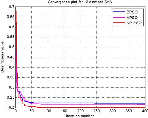
As shown in Figure 5, the NP-PSO algorithm demonstrated fast convergence while being more efficient than both the BPSO and APSO algorithms.
Figure 5. Convergence diagram of a 12-element CAA synthesis using the Amplitude-Only method
6.1.3 Synthesis of 20‑elements using amplitude only technique
Table 3 shows the amplitudes obtained using BPSO, APSO, and NP-PSO in the example of the 20-element CAA synthesis, with NP-PSO achieving an SLL of -24.57 dB and APSO and BPSO achieving 17.16 dB and -13.26 dB, respectively. Figures 6 and 7 show the radiation pattern as well as the convergence plots.
Table 3. Amplitudes of excitation for the optimized 20-element CAA
|
N = 20, d = λ/2 |
Amplitude excitations |
Max SLL (dB) |
|
BPSO |
0.46 0.37 0.23 0.48 0.46 0.87 0.97 0.80 0.91 0.97 0.98 0.57 0.86 0.38 0.03 0.49 0.18 0.82 0.94 0.84 |
-13.26 |
|
APSO |
0.87 0.36 0.74 0.61 0.83 0.93 0.84 0.89 0.43 0.74 0.76 0.75 0.40 0.46 0.61 0.31 0.49 0.66 0.49 0.56 |
-17.16 |
|
NP-PSO |
0.51 0.46 0.74 0.17 0.28 0.49 0.47 0.73 0.51 0.94 0.66 0.41 0.28 0.97 0.38 0.48 0.45 0.44 0.94 0.98 |
-24.57 |
Figure 6. Amplitude-only radiation pattern of an optimized 20-element CAA
Figure 7. Convergence diagram of amplitude-only synthesis of 20-element CAA
6.2 Circular antenna array synthesis utilizing the position-only method
In this example, as a consequence of maximizing the angular locations of the array's elements, the subsequent separate vector φi is supplied.
$\varphi_{i}=\left[\varphi_{i 1}, \varphi_{i 2} \quad \varphi_{i N}\right]$ (18)
and the population matrix is represented by:
$p o p=\left[\begin{array}{c}\varphi_{1} \\ \varphi_{2} \\ \vdots \\ \varphi_{n}\end{array}\right]=\left[\begin{array}{cccc}\varphi_{11} & \varphi_{12} & \cdots & \varphi_{1 N} \\ \varphi_{21} & \varphi_{22} & \cdots & \varphi_{2 N} \\ \vdots & \vdots & \cdots & \varphi_{1} \\ \varphi_{n 1} & \varphi_{n 2} & \cdots & \varphi_{n N}\end{array}\right]$ (19)
Each element of the vector I is chosen so that $\phi_{i N}<360^{\circ}$.
6.2.1 Synthesis of 8‑elements using position only technique
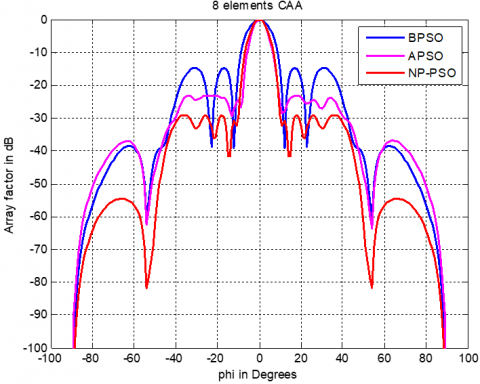
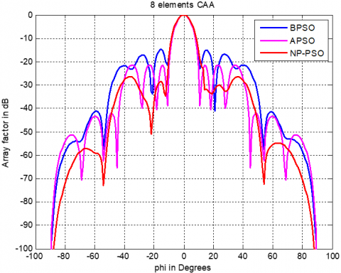
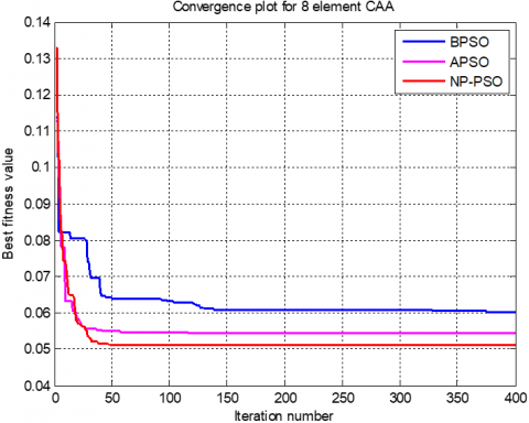
This example considers and synthesizes an 8-element CAA using the angular position-only method, and it is shown in Table 4 how to establish the spatial distribution of the array's components using the NP-PSO, APSO, and BPSO methods. In the radiation pattern depicted in Figure 8, NP-PSO has a greater suppression of maximum SLL, the convergence plots are given in Figure 9.
Table 4. Angular positions for the optimized 8-element CAA
|
N = 8, d = λ/2 |
Angular positions in degrees |
Max SLL (dB) |
|
BPSO |
36.12 56.19 131.36 151.98 216.90 252.91 300.22 34.30 |
-18.43 |
|
APSO |
33.45 66.76 102.91 146.69 202.35 221.16 76.96 112.81 |
-20.15 |
|
NP-PSO |
41.12 61.29 136.96 156.88 221.80 256.81 284.11 328.40 |
-29.06 |
Figure 8. Position-only radiation pattern of an optimized 8-element CAA
Figure 9. Convergence plot of an 8-element CAA synthesis by means of a position-only approach
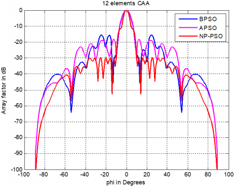
6.2.2 Synthesis of 12 elements using angular position only
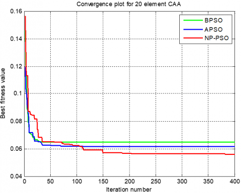
Figure 10 illustrates the radiation patterns produced using both techniques in 12-element CAA synthesis using an angular position-only technique and indicate a considerable improvement in the SLL. NP-PSO, APSO, and BPSO are used to determine the angular positions of the elements, as shown in Table 5. The convergence plots are shown in Figure 11, which allows us to observe the fast convergence of NP-PSO.
Table 5. Angular positions for the optimized 12-element CAA
|
N = 12, d = λ/2 |
Angular positions in degrees |
Max SLL (dB) |
|
BPSO |
0.60 15.15 59.30 91.93 103.68 100.56 168.11 205.40 251.05 266.63 282.01 328.19 |
-15.69 |
|
APSO |
7.64 21.58 66.01 98.34 110.88 157.69 175.11 210.09 258.50 273.33 289.11 334.96 |
-18.39 |
|
NP-PSO |
24.08 45.90 93.61 104.32 128.27 175.27 205.82 253.66 270.48 299.89 340.62 359.11 |
-29.71 |
Figure 10. Radiation pattern of an improved 12-element CAA using a position-only approach
Figure 11. Convergence diagram for a 12-element CAA synthesis using the position-only method
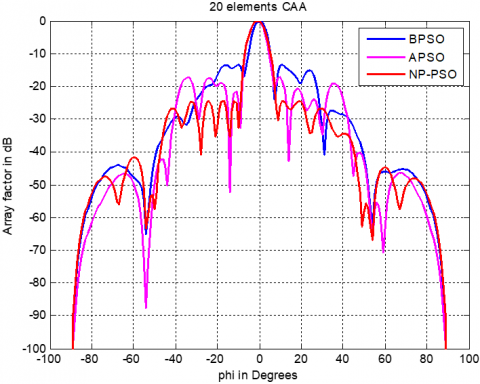
6.2.3 Synthesis of a 20-element system based solely on angular position
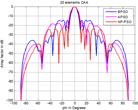
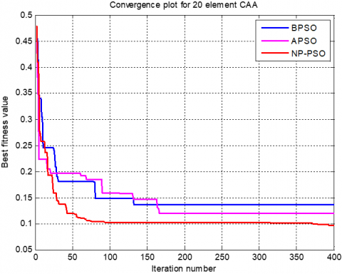
Figure 12 exhibits an evaluation of the radiation patterns of the 20-element CAA obtained using various techniques. The SLL values for 20 elements in the BPSO, APSO, and NP-PSO algorithm–based results are 14.59 dB, 17.46 dB, and 23.91 dB, respectively, and the improved values required to plot Figure 10 with both techniques are provided in Table 6. The convergence graph for the specified objective function for 20 antenna components is shown in Figure 13.
Table 6. Angular locations for the improved 20-element CAA
|
N = 20, d = λ/2 |
Angular positions in degrees |
Max SLL (dB) |
|
BPSO |
8.31 54.06 63.19 79.79 80.04 88.85 132.96 166.88 166.98 177.36 177.86 216.32 249.13 249.18 260.96 262.05 279.82 323.13 349.84 349.99 |
-14.59 |
|
APSO |
16.35 62.67 71.96 87.91 88.47 96.56 140.66 174.80 175.90 185.61 186.32 224.23 257.34 257.58 268.63 270.54 287.24 331.33 357.46 357.93 |
-17.46 |
|
NP-PSO |
5.54 37.56 82.54 87.41 93.57 94.36 95.14 123.11 167.26 177.13 178.98 188.68 223.53 262.44 271.68 272.16 277.35 313.85 357.94 359.63 |
-23.91 |
Figure 12. Viewpoint radiation pattern of an optimized 20-element CAA
Figure 13. The convergence curve of a 20-element CAA synthesis using the position alone approach
6.3 Synthesis of a circular antenna array combining the amplitude and position approach
Among the two previous examples, only one attribute was utilized in the optimization process. Furthermore, in multi attribute optimization methods, multiple variables can be considered such as an array's angular locations and amplitudes.
6.3.1 Synthesis of a 20-element system based solely on angular position
This approach can manage SLL by manipulating both the amplitudes and placements of the components. Both algorithms consistently created patterns with substantial performance in minimizing the maximum SLL in the first example of 8-element CAA synthesis using the Amp-Pos approach.
The magnitude and location distributions predicted by the BPSO, APSO, and NP-PSO are shown in Table 7. The SLL obtained using NP-PSO and APSO is substantially lower than the BPSO, as seen by the radiation pattern plots in Figure 14. Figure 15 depicts the consistency of the algorithms' performance in terms of convergence.
6.3.2 Synthesis of 12 Elements Using the Approach of Amplitude and Angular Position
As compared to the previous instance, the SLL of the 12-element CAA has improved significantly. Table 8 shows the outcomes of the three methods, which also includes the maximum SLL determined by the algorithms with the aim of suppressing SLL. In this case, Figures 16 and 17 show the radiation pattern and convergence plots for a 12-element CAA synthesis.
Table 7. The improved 8-element CAA's excitation amplitude and angular locations
|
N = 8, d = λ/2 |
Excitation-amplitude |
Angular positions in degrees |
Max SLL (dB) |
|
BPSO |
0.99 0.12 0.90 0.55 0.14 0.19 0.90 0.98 |
37.94 69.79 119.44 148.52 208.38 223.67 272.74 320.53 |
-14.77 |
|
APSO |
0.33 0.16 0.33 1 0.18 0.96 0.51 0.59 |
52.29 108.82 150.89 217.64 226.60 256.95 301.81 333.62 |
-21.4 |
|
NP-PSO |
0.93 0.90 0.33 0.15 0.20 0.60 0.51 0.95 |
40.98 96.21 138.98 205.44 214.02 244.56 289.19 321.62 |
-26.38 |
Figure 14. Amplitude and angular position approach was used to create a radiation pattern for an optimized 8-element CAA
Figure 15. Convergence diagram of an 8-element CAA synthesis utilizing the amplitude and position approach
Table 8. The improved 12-element CAA's excitation amplitude and angular locations
|
N = 12, d = λ/2 |
Excitation-amplitude |
Angular positions in degrees |
Max SLL (dB) |
|
BPSO |
0.44 0.81 0.93 0.04 0.93 1 0.14 0.03 0.75 0.36 0.12 0.13 |
21.19 52.47 92.07 103.03 132.23 160.65 198.43 249.47 276.94 287.93 338.32 354.69 358 |
-13.06 |
|
APSO |
0.78 0.59 0.18 0.72 0.22 0.09 0.05 0.23 0.37 0.34 0.75 |
9.71 40.04 80.70 91.30 120.82 148.06 186.34 237.64 264.79 275.29 334.32 342.68 350 |
-16.13 |
|
NP-PSO |
0.27 1 0.85 0.81 0.07 0.22 0.70 0.80 0.32 0.33 0.63 0.95 |
12.12 25.60 68.91 88.98 134.35 166.73 194.88 202.71 228.60 267.20 286.92 332.35 360 |
-25.22 |
Figure 16. Amplitude and angular position approach was used to create a radiation pattern for an optimized 12-element CAA
6.3.3 The amplitude and angular position approach used to synthesize 20 components
A 20 elements CAA is synthesized using the Amp-Pos approach with BPSO, APSO, and NP-PSO in this example. Consequently, the amplitudes and angular coordinates are determined using the methods shown in Table 9 as well as the estimated SLL maximum. As depicted in Figure 18, the NP-PSO performs better in terms of convergence. The radiation pattern chart in Figure 19 shows the same thing.
Figure 17. The convergence curve of a 12-element CAA synthesis combining the amplitude and position approach
Figure 18. Convergence diagram of amplitude and position approach for 20-element CAA synthesis
Table 9. The improved 20-element CAA's excitation amplitude and angular coordinates
|
N = 12, d = λ/2 |
Excitation-amplitude |
Angular positions in degrees |
Maximum SLL (dB) |
|
BPSO |
0.62 0.18 0.64 0.68 0.51 0.77 0.79 0.36 0.22 0.77 0.34 0.36 0.98 0.27 0.28 0.45 0.28 0.60 0.62 |
1.30 7.25 40.74 79.84 79.09 83.86 90.57 105.67 109.53 132.78 179.52 183.59 184.79 217.68 250.60 265.03 270.09 279.15 315.24 350.89 356.54 |
-12.97 |
|
APSO |
0.56 0.51 0.66 0.56 0.55 0.57 0.07 0.23 0.32 0.47 0.93 0.53 0.69 0.12 0.22 0.34 0.62 0.36 0.56 |
0.30 6.25 41.74 80.84 80.09 84.86 91.57 106.67 110.53 133.78 170.52 184.59 185.67 218.68 252.60 268.03 271.09 280.15 316.24 351.89 358.99 |
-17.14 |
|
NP-PSO |
0.50 0.02 0.18 0 0.78 0.95 0.24 0.20 0.24 0.04 0.05 0.62 0.96 0.81 0.03 0.80 0.11 0.48 0.65 1 0.07 |
5.95 42.66 62.82 81.05 93.52 105.44 106.78 112.46 113.63 136.96 168.89 180.62 186.26 222.79 254.21 268.68 268.64 281.18 318.02 354.59 359.66 |
-23.19 |
6.4 Comparative study
Table 10 compares the results achieved with NP-PSO to the results obtained with other methods for circular antenna array synthesis. Table 10 confirms that the SLL value achieved by using NP-PSO is the good quality when compared to the published findings obtained by utilizing previous algorithms such as CS [35] and HS [36]. Figure 20 illustrates the effect of the maximum SLL adopting various techniques.
Table 10. Maximum side lobes levels obtained by different algorithms for 20-element CAA
|
Algorithm |
Reference |
Maximum SLL |
|
Proposed study |
-31.45 dB |
|
|
CS |
[35] |
-11.96 dB |
|
HS |
[36] |
-19.63 dB |
Figure 19. Amplitude and angular position approach used to improve the radiation pattern of a 20-element CAA
Figure 20. Radiation pattern obtained by different algorithms for 20-element CAA
To reduce minimum SLL and beam width, this research developed a hybrid nonlinear programming and particle swarm optimization (NP-PSO) technique for circular antenna array (CAA) pattern synthesis. A hybrid approach is used to optimize the amplitude and placement (both amplitude and position) of CAA components. Three simulation design examples are shown, and their results are evaluated to individuals achieved by other developments algorithms such as CS and HS. The comparison simulation results demonstrate increased performance when compared to other methods such as basic PSO and adaptive PSO, notably in terms of directivity, minimal SLL, beam width control, and level of convergence.
[1] Panduro, M.A., Mendez, A.L., Dominguez, R., Romero, G. (2006). Design of non-uniform circular antenna arrays for side lobe reduction using the method of genetic algorithms. AEU-International Journal of Electronics and Communications, 60(10): 713-717. https://doi.org/10.1016/j.aeue.2006.03.006
[2] Khodier, M. (2013). Optimisation of antenna arrays using the cuckoo search algorithm. IET Microwaves, Antennas & Propagation, 7(6): 458-464. https://doi.org/10.1049/iet-map.2012.0692
[3] Singh, H., Mittal, N., Singh, U., Salgotra, R. (2022). Synthesis of non-uniform circular antenna array for low side lobe level and high directivity using self-adaptive cuckoo search algorithm. Arabian Journal for Science and Engineering, 47(3): 3105-3118. https://doi.org/10.1007/s13369-021-06059-8
[4] Sun, G., Liu, Y., Liang, S., Wang, A., Zhang, Y. (2017). Beam pattern design of circular antenna array via efficient biogeography-based optimization. AEU-International Journal of Electronics and Communications, 79: 275-285. https://doi.org/10.1016/j.aeue.2017.06.018
[5] Liang, S., Feng, T., Sun, G. (2017). Sidelobe-level suppression for linear and circular antenna arrays via the cuckoo search–chicken swarm optimisation algorithm. IET Microwaves, Antennas & Propagation, 11(2): 209-218. https://doi.org/10.1049/iet-map.2016.0083
[6] Mahto, S.K., Choubey, A. (2016). A novel hybrid IWO/WDO algorithm for nulling pattern synthesis of uniformly spaced linear and non-uniform circular array antenna. AEU-International Journal of Electronics and Communications, 70(6): 750-756. https://doi.org/10.1016/j.aeue.2016.02.013
[7] Chakravarthy, V.V.S.S.S., Chowdary, P.S.R., Dib, N., Anguera, J. (2022). Elliptical antenna array synthesis using evolutionary computing tools. Arabian Journal for Science and Engineering, 47(3): 2807-2824. https://doi.org/10.1007/s13369-021-05852-9
[8] Das, A., Mandal, D., Kar, R. (2021). An optimal compact time-modulated circular antenna array synthesis using krill herd optimization. Annals of Telecommunications, 76(7): 467-482. https://doi.org/10.1007/s12243-020-00827-7
[9] Kennedy, J., Eberhart, R. (1995). Particle swarm optimization. In Proceedings of ICNN'95-International Conference on Neural Networks, 4: 1942-1948. https://doi.org/10.1109/ICNN.1995.488968
[10] Najjar, M.S.Y., Khodier, N.D.M. (2008). Design of non–uniform circular antenna arrays using particle swarm optimization. Journal of Electrical Engineering, 59(4): 216-220.
[11] Haupt, R.L., Werner, D.H. (2007). Genetic Algorithms in Electromagnetics. John Wiley & Sons.
[12] Panduro, M.A., Mendez, A.L., Dominguez, R., Romero, G. (2006). Design of non-uniform circular antenna arrays for side lobe reduction using the method of genetic algorithms. AEU-International Journal of Electronics and Communications, 60(10): 713-717. https://doi.org/10.1016/j.aeue.2006.03.006
[13] Ingber, L. (1993). Simulated annealing: Practice versus theory. Mathematical and Computer Modelling, 18(11): 29-57. https://doi.org/10.1016/0895-7177(93)90204-C
[14] Rattan, M., Patterh, M.S., Sohi, B.S. (2009). Optimization of circular antenna arrays of isotropic radiators using simulated annealing. International Journal of Microwave and Wireless Technologies, 1(5): 441-446. https://doi.org/10.1017/S1759078709990687
[15] Singh, U., Kamal, T.S. (2011). Design of non-uniform circular antenna arrays using biogeography-based optimisation. IET Microwaves, Antennas & Propagation, 5(11): 1365-1370. https://doi.org/10.1049/iet-map.2010.0204
[16] Sharaqa, A., Dib, N. (2014). Circular antenna array synthesis using firefly algorithm. International Journal of RF and Microwave Computer-Aided Engineering, 24(2): 139-146. https://doi.org/10.1002/mmce.20721
[17] Ram, G., Mandal, D., Kar, R., Ghoshal, S.P. (2015). Circular and concentric circular antenna array synthesis using cat swarm optimization. IETE Technical Review, 32(3): 204-217. https://doi.org/10.1080/02564602.2014.1002543
[18] Das, A., Mandal, D., Ghoshal, S.P., Kar, R. (2019). Moth flame optimization based design of linear and circular antenna array for side lobe reduction. International Journal of Numerical Modelling: Electronic Networks, Devices and Fields, 32(1): e2486. https://doi.org/10.1002/jnm.2486
[19] Munson, D. C., O'Brien, J.D., Jenkins, W.K. (1983). A tomographic formulation of spotlight-mode synthetic aperture radar. Proceedings of the IEEE, 71(8): 917-925. https://doi.org/10.1109/PROC.1983.12698
[20] Hu, X., Eberhart, R. (2002). Solving constrained nonlinear optimization problems with particle swarm optimization. In Proceedings of the Sixth World Multiconference on Systemics, Cybernetics and Informatics, 5: 203-206.
[21] Parsopoulos, K.E., Vrahatis, M.N. (2002). Particle swarm optimization method for constrained optimization problems. Intelligent Technologies–Theory and Application: New Trends in Intelligent Technologies, 76(1): 214-220.
[22] Hu, X., Eberhart, R.C., Shi, Y. (2003). Engineering optimization with particle swarm. In Proceedings of the 2003 IEEE Swarm Intelligence Symposium. SIS'03 (Cat. No. 03EX706), pp. 53-57. https://doi.org/10.1007/s40747-021-00402-0
[23] Parsopoulos, K.E., Vrahatis, M. N. (2002). Recent approaches to global optimization problems through particle swarm optimization. Natural Computing, 1(2): 235-306. https://doi.org/10.1023/A:1016568309421
[24] Luo, Y.Q., Yuan, X.G., Liu, Y.J. (2007). An improved PSO algorithm for solving non-convex NLP/MINLP problems with equality constraints. Computers & Chemical Engineering, 31(3): 153-162. https://doi.org/10.1016/j.compchemeng.2006.05.016
[25] Thazeen, S., Mallikarjunaswamy, S., Siddesh, G.K., Sharmila, N. (2021). Conventional and subspace algorithms for mobile source detection and radiation formation. Traitement du Signal, 38(1): 135-145. https://doi.org/10.18280/ts.380114
[26] Mandal, D., Ghoshal, S.P., Bhattacharjee, A.K. (2013). Optimized radii and excitations with concentric circular antenna array for maximum sidelobe level reduction using wavelet mutation based particle swarm optimization techniques. Telecommunication Systems, 52(4): 2015-2025. https://doi.org/10.1007/s11235-011-9482-8
[27] Kennedy, J., Eberhart, R. (1995). Particle swarm optimization. In Proceedings of ICNN'95-International Conference on Neural Networks, 4: 1942-1948. https://doi.org/10.1109/ICNN.1995.488968
[28] Shi, Y. (2001). Particle swarm optimization: developments, applications and resources. In Proceedings of the 2001 Congress on Evolutionary Computation (IEEE Cat. No. 01TH8546), 1: 81-86. https://doi.org/10.1109/CEC.2001.934374
[29] Eberhart, R.C., Shi, Y. (1998). Comparison between genetic algorithms and particle swarm optimization. In International Conference on Evolutionary Programming, pp. 611-616. https://doi.org/10.1007/BFb0040812
[30] Lakhlef, N., Oudira, H., Dumond, C. (2020). Optimal pattern synthesis of linear antenna arrays using modified grey wolf optimization algorithm. Instrumentation, Mesure, Métrologie, 19(4): 255-261. https://doi.org/10.18280/i2m.190402
[31] Parsopoulos, K.E., Vrahatis, M.N. (2002). Particle swarm optimization method for constrained optimization problems. Intelligent technologies–theory and application: New Trends in Intelligent Technologies, 76(1): 214-220.
[32] Hu, X., Eberhart, R.C., Shi, Y. (2003). Engineering optimization with particle swarm. In Proceedings of the 2003 IEEE Swarm Intelligence Symposium. SIS'03 (Cat. No. 03EX706), pp. 53-57. https://doi.org/10.1007/s40747-021-00402-0
[33] Parsopoulos, K.E., Vrahatis, M.N. (2002). Recent approaches to global optimization problems through particle swarm optimization. Natural Computing, 1(2): 235-306. https://doi.org/10.1023/A:1016568309421
[34] Tuhvatullin, M., Arkhangelsky, Y., Aipov, R., Khasanov, E. (2021). Ultra high-frequency electric installation with a hybrid-type working chamber. Mathematical Modelling of Engineering Problems, 8(6): 937-944. https://doi.org/10.18280/mmep.080613
[35] Sun, G., Liu, Y., Liang, S., Wang, A., Zhang, Y. (2017). Beam pattern design of circular antenna array via efficient biogeography-based optimization. AEU-International Journal of Electronics and Communications, 79: 275-285. https://doi.org/10.1016/j.aeue.2017.06.018
[36] Singh, H., Abouhawwash, M., Mittal, N., Salgotra, R., Mahajan, S., Pandit, A.K. (2022). Performance evaluation of non-uniform circular antenna array using integrated harmony search with Differential Evolution based Naked Mole Rat algorithm. Expert Systems with Applications, 189: 116146. https://doi.org/10.1016/j.eswa.2021.116146