Sa'adatu Abubakar | Azizulrahman Bin Mohd Shariff* | Khuzairi Mohd Zaini | Suzi Iryanti Fadilah | Mustapha Abubakar Ahmed
© 2022 IIETA. This article is published by IIETA and is licensed under the CC BY 4.0 license (http://creativecommons.org/licenses/by/4.0/).
OPEN ACCESS
Vehicle-to-Vehicle (V2V) communication is considered the enabler of road safety, traffic efficiency, and compatibility for drivers, passengers, and vulnerable road users. The evolution of 5G V2X enhances the physical layer of LTE V2X in terms of resource allocation, frame structure, and many more. The amendments in the physical layer are to enable the exchange of safety and advanced driving services within a geographical area. The introduction of 25 use cases in the 3GPP Release 15 standard with different quality of service (QoS) requirements and high demand for data rates makes it possible for the enhancements. Delivering the services of the established use cases becomes a challenge in 5G-V2V communication. Release 14 and release 15 mark the evolution of LTE V2X, while Release 16 highlights 3GPP advancements for 5G V2X NR services, and Release 17 focuses on future enhancements with the applications of Machine Learning (ML) and Artificial Intelligence (AI). This study examines sidelink communication, resource allocation for LTE V2V and 5G-V2V, and NR V2X enablers such as Network Slicing (NS) and Machine Learning (ML) with recent capacity studies on V2V employing the two 5G enablers. In 5G-V2V Sidelink communication, Physical Sidelink Shared Channel (PSSCH) is responsible for broadcasting various messages using release 14 and release 16 waveforms. The capacity of PSSCH to broadcast the 5G services, such as Cooperative Awareness Messages (CAM), Decentralized Environmental Messages (DENM), Light Detection and Ranging (LIDAR) contents for environmental perception, and sensor DATA applications for driving intention, becomes a challenge. This study considered this challenge by providing a mathematical model of the capacity of V2V and V2I links in the 5G V2X network for mode selection using the Poisson point process and Poisson line process within a circular region.
3GPP, LTEV2X, sidelink communication, sidelink capacity, network slicing, machine learning
According to the World Health Organization (WHO), the Road Traffic injury statistics of all countries show that after the year 2000, road accidents are the primary cause of death [1]. Another report in 2018 indicates that about 1.3 million people die annually, with 20-50 injured, particularly in the low and middle-income countries [2]. An intelligent transportation system (ITS) is established to overcome the problem. In the Intelligent Transportation System (ITS), modern vehicles are equipped with sensors, a navigation system, and communication devices to allow data collection and information sharing with vehicles being aware of their environment [3]. ITS consists of a wide variety of communications-related applications intended to increase road safety, minimize environmental impact, improve traffic management, and maximize the benefit of transportation to both commercial users and the public, ETSI [4].
Concerning the applications of ITS, the communication of the vehicles is categorized into four types, namely (1) vehicle-to-vehicle (V2V) communication, (2) vehicle-to-pedestrian (V2P) communication, (3) vehicle-to-infrastructure (V2I) communication, and (4) vehicle-to-network (V2N) communication as mentioned in 3GPP [5]. While the first and the second categories are based on device-to-device (D2D) communication, the third and the fourth application categories depend on infrastructure. D2D communication is an LTE-A feature introduced in 3GPP release 12 [6] to enable devices to communicate when in proximity. D2D communication is thoroughly reviewed by Jameel et al. [7]. In the LTE V2X, a vehicle communicates with the neighboring vehicles to exchange safety messages within the same communication range. But in 5G V2X, the vehicles are expected to exchange safety messages and share advanced driving applications. 3GPP Release 15 and 16 brought about backward compatibility as one of the enhanced features of 5G V2X where VUEs communicate with release 14 (LTE V2X) Waveform to broadcast the safety messages and with release 16 waveform for unicast, group cast, and broadcast transmission within the same 5.9 GHz ITS band [8].
In 1999, the United States Federal Communication Commission (US FCC) allocated a 75MHz spectrum band over the IEEE 802.11p protocol within the 5.850-5.925 GHz band for high-priority and traffic management applications. The allocated band is divided into 30 upper bands (180,182, 184) and 45 lower bands (172,174, 176, and 178). The 30 MHz allocation supports the current operations and future ITS needs, while the 45 MHz is allocated for the unlicensed operations. With the evolution of LTE V2V and NR V2V communication and the introduction of new vehicular services, the allocated band remains the same, which becomes a challenge in vehicular communication due to the high increase in device connectivity and the dynamic complexity of the system.
The FCC proposes revising the present ITS rule for the 5.9 GHz band on November 21, 2019, to allow C V2X to operate in 20 MHz out of the 30 MHz allocated for ITS. It also wants feedback on whether the remaining 10 MHz should be kept for DSRC or dedicated to C V2X [9]. The FCC released another Notice of Proposed RuleMaking (NPRM) on February 6, 2020, with the goal of re-allocating the bulk of the current 5.9 GHz spectrum to services other than ITS [10]. From February to March 6, 2020, the FCC received 286 comments in response to the proposed rulemaking. Nine percent (9%) of the submissions favor the NPRM, 89% express their view to oppose this proposed motion by mentioning safety use case as the most demanding spectrum compared to other services, and 2% are neutral, meaning they do not take a position.
Two safety messages are introduced in the European Telecommunication Standard Interconnects (ETSI) [11] to be transmitted among the vehicles for reliable communication. The messages are the Cooperative Awareness Message (CAM), like the Basic Safety Message for DSRC in the US, and the second message is the Decentralized Environmental Notification Message (DENM) transmitted by some vehicles in their vicinity [12]. Transmitting these messages with reliability and low latency is crucial because vehicle safety requires stringent (good) latency, adequate bandwidth, and low loss. V2V communication is termed Vehicular Ad-hoc NETwork (VANET) and differs in size, speed of the vehicles, the relevance of their geographic positions, and, have sporadic connectivity. Because of these characteristics and the integration of various sensor devices, VANET shows many challenging issues including routing, data dissemination and data sharing, and security. The vehicular security and automatic detection and plotting of the road security images are studied by Kanumalli et al. [13], and Airault and Jamet [14].
Combining the information provided by the sensors of other vehicles and the roadside infrastructure (e.g., obstacles, road surface conditions, and planned maneuvers) with the local perception provided by onboard sensors, such as the Global Positioning System (GPS), Light Detection and Ranging (LiDAR), RAdio Detection and Ranging (RADAR), and cameras, will improve the perception of the surroundings and overall vehicle safety. Due to the high data rate requests made by NR V2X services and the physical layer enhancements introduced by 3GPP standards to enable full automation of 5G NR V2V (sidelink) communication, ensuring safety in the NR V2X scenario has become difficult. The evolution of LTE V2X and NR V2X and their improvements are depicted in a timeline in Figure 1.
In this article, the capacity challenge of the sidelink V2V channel in delivering 5G services for safety and enhanced driving services (CAM, DENM, LIDAR, and sensor DATA) is highlighted. The study describes four alternative transmission scenarios that indicate how the channel can supply these services. As mentioned in the study, we review numerous research on resource allocation and many more on NS as a 5G enabler. To our knowledge, no study has considered the capacity of the sidelink V2V radio channel for CAM, CAM plus DENM, CAM plus DENM plus LIDAR, and CAM plus DENM plus LIDAR plus sensor DATA over the same PSSCH, which poses a significant threat to the safety of the 5G V2X network.
The remainder of the paper is laid out as follows. The physical layer enhancements in Release 14 and Release 15 LTE V2X are discussed in Section II. Section III briefly addressed the architecture of a V2V service based on 5G V2X, QoS support for Uu and PC5 interfaces, 5G V2X use cases, and their QoS requirements as specified in the 3GPP standard. The section highlights Release 16 physical layer enhancements for 5G V2X in terms of the numerology and SCS, frame structure, physical channels, and an overview of those enhancements and Release 17 futures. The mode of radio resource allocation in 5G V2X for mode 1 and sub-mode 2 introduced in version 16 is also covered in this section. Section IV examines V2V sidelink direct communication and design and the overall V2V communication architecture for 5G NR based on ETSI communication architecture. In this section, we formulate a mathematical model of queueing theory for estimating the PSSCH capacity in C V2X network. The idea of Network Slicing and Machine Learning for current research on vehicular communications are covered in Section V. Section VI discusses and concludes the article with research ideas for the future.
Figure 1. C V2X Release 14, 15, 16, and 17 enhancements for NR V2X
In 3GPP Release 14, the LTE-V2X Random Access Technology (RAT) was introduced (in LTE (4G)) to complement and cohabit with the DSRC and its European counterpart ITS-G5. Because the IEEE802.11p protocols suffer from bounded latency, LTE-V2X will meet vehicular requirements that the IEEE802.11p protocols cannot meet in terms of quality of service (QoS) support. Another advantage of LTE V2X over IEEE 802.11P is that LTE V2X's short range of communication serves as the foundation for most applications for autonomous and connected vehicles, and each vehicle can transmit its attributes such as position and speed via short-range V2V communication. DSRC was the first technology for vehicular safety launched in the United States, with Basic safety messages and spectrum allocation within the 5.9 GHz band. DSRC is observed on a widely deployed Wireless Local Area Network (WLAN) standard defined in 2013. The physical and MAC layers of the protocol are derived from the preceding IEEE802.11a standard and applied to the V2X requirements. 3GPP defined new physical and medium access control levels for C V2X in release 14 [5] while maintaining the higher layers of the ETSI standard.
2.1 Physical layer
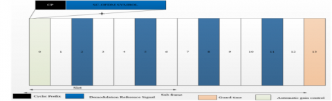
The LTE-V2X frame structure is 10 ms long and is divided into ten subframes, each of which is 1 ms wide and has a 2-time slot, like the LTE frame. A time slot is a 0.5-millisecond interval corresponding to seven single carrier frequency division multiple access (SC-FDMA) symbols. Using a 15KHz cyclic prefix (CP) spacing, 1 ms in the time domain translates to 14 OFDM symbols. The smallest time resolution is one subframe, whereas the smallest frequency resolution is 12 subcarriers at 15KHz each (i.e., 180KHz). A Resource Block (RB) is a transmitting resource unit consisting of 12 frequency subcarriers and a one-time slot (0.5ms) in the time domain. There are 12x7=84 resource elements in a resource block. In LTE subframes, a resource element is the smallest transmission unit, consisting of one subcarrier in the frequency domain and one SC-FDMA symbol in the time domain. A Scheduling Block (SB) is formed by two successive time-domain symbols, with each scheduling block (2 RBs) containing 168 resource elements. The number of RBs in a subcarrier is determined by the packet size and the modulation and coding rate. LTE-V2X supports 10 MHz and 20 MHz channels; a 10 MHz bandwidth has a frequency domain length of 50 RBs and a time-domain length of 20 RBs. Every subcarrier in LTE-V2X has 14 orthogonal symbols in a subframe with 4 DMRS, contrary to other LTE frames that carry two DMRS. The two DMRS are added to operate in a high-mobility environment [15]. Figure 2 depicts the LTE-V2X subframe structure. The four DMRSs occupy the third, sixth, ninth, and twelfth symbols; the first symbol is Automatic Gain Control (AGC), and the last symbol is the guard band.
In sidelink transmission, data is transmitted across the physical sidelink shared channel (PSSCH) in different Transport Blocks (TB) per time slot. Every TB transmission is associated with its corresponding Sidelink Control Information (SCI) broadcast in the Physical Sidelink Control CHannel (PSCCH). SCI comprises adjacent information required for proper reception and demodulation of relevant data (TBs) and takes up two RBs per time slot. Each UE must transmit TB and the related SCI in the same frame as described in 3GPP Rel.14. A TB can be made up of a whole package of safety messages (such as CAM or DENM) or non-safety messages [16]. 3GPP does not specify the number of RBs allocated to a TB (TB size); hence, it depends on the MCS, and coding rate used. TB and SCI might be adjacent or non-adjacent and separated [17]. In adjacent resource allocation both PSCCH, which carries the SCI, and PSSCH, which carries the TB, are communicating in an adjacent manner within a single resource pool. If the TB spans more than one subchannel, it takes up resource block pairs (RBPs) that may be utilized for SCIs. The 3GPP subchannel sizes available in the adjacent configuration are RA = {5, 6, 10, 15, 20, 25, 50, 75, 100}[18]. In non-adjacent transmission, the RBs are divided into two pools, one for SCI transmission and the other for data transfer. If a single TB is assigned to multiple subchannels, the resource block pairs (RBPs) corresponding to the SCIs of the additional subchannels are left empty. The allowable values for non adjacent resource are RN ={4, 5, 6, 8, 9, 10, 12, 15, 16, 18, 20, 30, 48, 72, 96}[18]. The advantage of non-adjacent is that, since the subchannel size does not contain the two RBPs for the SCI, if the TB requires 12 RBPs and the subchannel size is rs = 4, for example, three subchannels are fully utilized.
The Physical Sidelink Shared CHannel (PSSCH) resource pool comprises available sub-channels for data transmission. In contrast, the PSCCH resource pool comprises resources for SCI transfer [19].
Figure 2. LTE V2X with four demodulation enhancements
Each OFDM subcarrier in LTE V2X can use either Quadrature Phase Shift Keying (QPSK) or 16 Quadrature Amplitude Modulation (16-QAM) with turbo coding for modulation and coding (MCS) [20]. 3GPP Release 15 adds Carrier Aggregation (CA), transmission diversity, and 64 QAM to Release 14 for sidelink transmission, allowing the network to achieve even higher throughput and lower latency [21]. LTE V2X UEs broadcast control information and reference signals in the data (TB) symbols, together with DMRS which is used for channel estimation.
2.2 Radio resource allocation in LTE V2X
In LTE V2X, the method of allocating resources to Vehicular User Equipment (VUE) follows the resource allocation defined in Release 14 [5]. The infrastructure is responsible for allocating resources to VUE within its coverage called the sidelink mode 3 communication. For the VUEs outside the infrastructure coverage, the resources are pre-configured by the higher layer through the RRC layer as mentioned in 3GPP release 15. This can be accomplished by creating a subchannel with two RBs dedicated to sidelink control information and the rest for data [22]. When the VUE is in the infrastructure coverage, the resource pools are configured by eNB through the RRC in dedicated or broadcast signaling. The infrastructure is responsible for scheduling the transmission of sidelink control information within the configured resource pools.
Similarly, if the autonomous UE for sidelink communication is outside the coverage of the infrastructure, the VUE is pre-configured with a set of data transmission and reception pools. In each case, the RRC layer simultaneously checks the availability of cell coverage and efficiently selects the allocation mode. Depending on the nature of traffic to be transmitted the RRC layer configures the priority information in the sidelink control information (SCI) and hands it over to the MAC layer to configure the sidelink grant and execute the scheduling. The MAC layer obtains the time and frequency resources from the PHY layer [5]. Figure 3 shows how RRC performs mode selection and resource allocation procedures.
Figure 3. RRA and mode selection in mode 3 and mode 4 communication
Both within coverage (mode 3) and out of coverage (mode 4) users should be configured with the resource pool for PSCCH and PSSCH to ensure safe transmission. VUEs for the two modes obtain their spectrum resources from the same sensing window for reliable data exchange and proper spectrum utilization. In LTE V2V communication, sensing-based semi-persistence scheduling (SB-SPS) is mainly for safety applications. Each VUE must monitor all the communication channels and signal sensing from nearby VUEs. The sensing result is recorded and forwarded to the MAC layer by each VUE that checks the received signals. Depending on the number of re-selection counters, the reported result is reserved in the MAC layer in a semi-persistent approach for later transmission.
Packets are sent every 100 milliseconds, allowing a vehicle to transmit ten packets per second (10 PPS). Whenever a vehicle intends to transmit a packet for which the reservation counter resources do not match that transmission, the vehicle must select a new resource for the required service transmission. After each selection, the number of sub-channels in the selection counter decreases by one. When it reaches zero, new resources must be selected and reserved with the probability (1-p), set between 0 and 0.8 [23]. Higher probability allows VUEs to keep their chosen resources for a more extended period. The physical layer then maps the resulting message to the PC5 interface for transmission.
The following steps are involved in the sensing base-semi persistence scheduling:
Step 1: In each TTI, a transmitter VUE identifies a list L1 of N Resource Elements (RE) in the sensing window, also known as Candidate Single subframe Resources (CSR). CSRs are adjacent or non-adjacent resources required for SCI and TB transmission. In sidelink communication, resource scheduling is considered in an adjacent manner within the selection window; the set of all allocated resources can be represented as
$L 1=R 1, R 2, \ldots R N$ (1)
The transmitter VUE searches all the resources in the CSR and excludes those already reserved by other VUEs (persistent scheduled) in the previous 1000 TTI. The status of the RE depends on the Reference Signal Received Power (RSRP) value. If the measured RSRP in the list of the resources exceeds a specified threshold value, it indicates that the resources are in use by another UE.
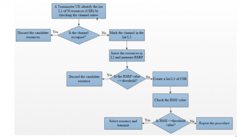
Step 2: The list L2 must contain at least 20% of the selection window; otherwise, increase the threshold value by 3dB and loop again, as indicated in 3GPP release 14. The RSRP value is configurable meaning it is not fixed and ranges between -40dB to -140dB. RSRP threshold depends on the reference signal strength indicator (RSSI), and the number of RBs which depends on the cell bandwidth. The transmitting vehicle uses the list L2 to measure the state of CSRs in ascending order of their Reference Signal Strength Indicator (RSSI) value and creates a new list L3 with the resources that have low RSSI. Eq. (2) is used to calculate the average RSSI value over the previous transmission. Molina-Masegosa [23] investigated system-level modeling, the mode 4 sensing operation depends on the RSSP threshold and the reservation probability (p). The reference signal received indicator is defined by 3GPP as
RRIvalue $=t T x-T * j$ (2)
where, T is the number of subframes, and j is a positive integer. If a VUE selects an RRI > 100 ms, then T=100 ms; similarly, if the picked RRI > 50, then T=50 ms; also, if the selected RRI > 20, then T= 20 ms and happens for each subframe in the sensing window that has been allocated [24].
Figure 4. An illustration of mode 4 sensing procedure
Step 3: The L3 list contains CSRs from L2 that have a low RSSI value over the RBs; those CSRs with a low RRSI value are the required CSRs for transmission since a low RSSI value indicates that another UE has not used the resource during the TTI. From the list L3, a VUE is free to choose the available resource and use it for the transmission. Figure 4 depicts the flowchart for the sensing procedure in mode 4 communication.
In mode 3, the eNB configures the sidelink parameters such as carrier frequency, sub-channel, and time slot [25]. The sidelink design introduced in releases 14 and 15 represents the beginning of the sidelink communication for NR V2X applications previously not supported by mobile communication technology due to its high speed and high-density scenarios. In release 14 the physical layer of the LTE V2X is designed to enable mode 3 and mode 4 communications while in release 15 the physical layer of the LTE V2X is enhanced to support 5G NR V2V modes of communication for release 16 and to allow backward compatibility between LTE-V2X and NR V2X users.
3.1 5G NR V2X service architecture for V2V communication
The 5G V2X system architecture differs from LTE V2X architecture as it connects everything, every time, and everywhere. It enables both non-standalone and stand-alone deployment. It includes a 5G Core (5G-C), 5G Random Access Network (5G-RAN), and 5G User Equipment (5G-UE) that operate in the 6 GHz (FR1) and millimeter WAVE (FR2) frequency bands [26]. 5G V2X architecture is specified by 3GPP Release 16 [27, 28] based on 5G NR architecture. Figure 5 presents the 5G V2X service architecture.
The architecture comprises the PC5 interface supporting sidelink communication between the 5G V2X UEs; the Uu cellular interface that connects the vehicular user equipment (VUE) to the 5G NR base station (gNB). V2X configuration parameters such as radio, Qos, and other V2X parameters are provided via the Policy Control Function (PCF).
According to release 16, the NetWork Data Analytic Function (NWDAF) delivers the quality-of-service analytic information to improve V2X communications. The access and mobility management entity manages the registration, mobility, and authentication of the VUEs. The user plane function (UPF) connects the NG-RAN to the V2X core network via the NG interface. The network data analytic function in the 3GPP 5G core network supports 5G V2X sidelink communication over the Uu interface. A V2X application server may request information about the QoS difference for the communication area and the time interval from the 3GPP network to change the application behavior ahead of time [29]. Within the 3GPP network, the NWDAF collects 3GPP data and extracts statistical information on the QoS difference, which it retains for future V2X applications.
Figure 5. The 5G V2X service architecture
3.1.1 NR-V2X QoS support for the Uu interface
As stated in release 16, 5G V2X supports Quality of Service criteria for Uu and PC5 interfaces. By requesting information from the 3GPP network, the V2X application server enables QoS through the Uu cellular interfaces for uplink (UL) and downlink (DL) transmission. The NWDAF generates information based on QoS measurement data and statistics regarding QoS changes, which are later forwarded to the V2X application server [29].
3.1.2 NR V2X QoS support over the pc5 interface
Communication between V2X devices through the sidelink PC5 is compatible with 3GPP release 14 for Proximity Per Packet Priority (PPPP), which defines the transmission of V2X packets with a value range of 8 [30]. The V2X application either assigns the PPPP value to the UE or the higher layer pre-configures it. Release 15 supports the same approach, but the PPPP mechanism has been enhanced by the addition of Prose Per Packet Reliability (PPPR), which allows the Access Stratum (AS) layer to determine whether the V2X packet needs to be reliably transmitted over multiple carriers on the sidelink, as stated in 3GPP release 16 [31]. A V2X application packet is passed to the V2X layer, including a set of PC5 QoS rules based on the PCF QoS rules. The V2X layer assigns a QoS flow ID to the V2X packet, then forwarded it to the AS Service Data Adaptation Protocol (SDAP). The Radio Link Control (RLC) buffer stores RLC Service Data Units (SDUs), which are retrieved by the underlying MAC (Media Access Control) layer when it needs to assemble a transmission. The MAC assembles RLC Protocol Data Units (PDUs) into Transport Blocks (TBs), adds a MAC header, and transmits everything over the physical (PHY) layer [32]. Other features include allowing Hybrid Automatic Report reQuest (HARQ) with feedback for group cast communication, as well as creating an associated transport block (TB) and forwarding it to the physical layer for transmission [33].
3.2 5G-V2X use cases and service requirements
To ensure optimal safety and dependability, 3GPP [34, 35] divides NR V2X services into different use cases, each with a set of service criteria. 5G NR use cases and their service requirements are discussed next.
3.2.1 NR V2X use cases
3GPP defined 25 use cases for 5G V2X services to support safety and advanced information sharing among the VUEs within a minimum communication range (MCR). The 25 use cases are categorized as follows:
• Advanced driving supports semi-automated and fully automated driving with a sizeable inter-vehicular distance. In this use case, each ITS station (VUE or RSU) shares data from its local sensor with the UE in its immediate vicinity. Advanced driving enables a vehicle to coordinate trajectories or maneuvers and share its driving abilities with other vehicles around it. This use case enhances road safety, traffic efficiency, and collision avoidance.
• Platooning allows VUEs to drive in a convoy by creating a group and traveling together in real-time. The platoon leader is the vehicle in the front of the platoon which leads the group. All other platoon members get periodic data from the leading VUE to carry out platoon operations. This use case allows the platoon vehicles to be separated by only a small distance. The time-domain of the space between the vehicles is reduced to a few milliseconds (ms).
• The extended sensor enables the VUEs, RSUs, Pedestrian devices, and V2X application servers to exchange raw and processed data compiled from the local sensor and the video streaming. Using the collected data, a VUE can comprehend information outside its sensor data.
• Remote driving is particularly appropriate for passengers who do not know how to drive or when the vehicle is in a hazardous location. A remote driver can operate a remote VUE with slight variance and predictable routes via remote driving.
3.2.2 5G-V2X service requirements
3GPP specifies the 5G V2X service requirements for the classified use cases to enable seamless and safe communication between VUEs. The Level of Automation (LOA) reflects the functional element of the technology and influences the system performance need. The LOA is a crucial aspect of advanced V2X applications, as indicated by the Society of Automation Engineers (SAE), which published a standard (J3016) that classified vehicle driving into six stages from level 0 to level 5 [36]. The six levels of automation as illustrated in Figure 6 start from level 0 in which there is no automation followed by level one which requires driver assistance, level 2 is partial assistance, level 3 is conditional assistance, and level 4 is high automation while level 5 is full automation.
The 5G V2X use cases and their service requirements are presented in Table 1.
Figure 6. The six levels of automation
Table 1. ETSI/3GPP use cases and service requirements
|
Use Cases |
Payload (byte) |
Tx-rate |
Max-latency (ms) |
Reliability (%) |
Data rate (Mbps) |
Min-range (m) |
|
ETSI CAM |
50-300 |
100 |
100 |
99.99 |
10 |
300-500 |
|
ETSI DENM |
400-1200 |
- |
100 |
99.99 |
- |
300-500 |
|
Platooning |
50-600 |
2-50 |
10-25 |
90-99.99 |
<65 |
80-350 |
|
Adv. Driving |
300-12000 |
10-100 |
10-100 |
90-99.99 |
10-50 |
360-700 |
|
Extended Sensor |
1600 |
10 |
3-100 |
90-99.99 |
10-1000 |
50-1000 |
|
Remote Driving |
1600-47100 |
33-200 |
5 |
99.999 |
UL:25 DL:1 |
1000 and above |
3.3 5G V2X physical layer design for sidelink communication
The 5G-V2X physical and protocol layers for sidelink need to be enhanced to accommodate different communication types and ensure ULLRC for periodic and aperiodic traffic. The 5G V2X physical layer design is based on the following:
3.3.1 Numerology
The frame structure of 5G NR in the physical layer uses variable Numerology with different SubCarrier Spacing (SCS) and flexible slot-based structures. Unlike LTE V2X which uses only 15KHz SCS, 5G V2X uses 30 kHz, 60 kHz, 120 kHz, and 240 kHz depending on the Numerology used (µ= 0,1,2,3,4). The 15 kHz, 30 kHz, and 60 kHz frequencies are designated for the support of sub-6 GHz (i.e., the FR1), whereas the 60 and 120 kHz frequencies are designated to support the frequency band above 6 GHz (the FR2 frequency range). 5G differs from LTE-Advance in frame structure due to its support of flexible Numerology for different subcarrier spacings, waveform generation with CP-OFDM for release 14 and release 16 UEs, 5G resource pool design, and use of bandwidth path as detailed in the next subsections. In 5G services, a substantial bandwidth is necessary to meet the 20 Gbps stated by IMT-2020 [37, 38]. However, the 5G V2X frequency range is categorized into two:
• Frequency Range 1 (FR1) (450 MHz-6000 MHz), also known as the sub-6GHz band, overlaps with LTE frequencies.
•The millimeter-wave (mm-wave) band spans the Frequency Range 2 (FR2) (24 GHz-52 GHz).
Although both frequency bands enable NR V2X, the sidelink communication design is based on FR1, except for addressing phase noise, which is more prominent at higher frequencies [26].
3.3.2 5G V2X frame structure
When 15kHz CP is utilized, the 5G-V2X frame structure is 10 ms long and is divided into 10 subframes, each 1ms wide like LTE-V2X. A Cyclic Prefix (CP) of 15kHz, 30kHz, 60kHz, and 120kHz spacing corresponds to a time slot of 1ms, 0.5ms, 0.25 ms, and 0.125 ms. In NR V2X, a slot consists of 12 subcarriers in the frequency domain and the number of OFDM symbols in the time domain depends on the SCS used.
3.3.3 Waveform
Unlike release 14, where the LTE-V2X supports Single Carrier Orthogonal Frequency Division Multiple Access (SC-OFDMA) in the uplink and OFDMA in the downlink, the 5G sidelink design supports Cyclic Prefix Orthogonal Frequency Division Multiplexing (CP-OFDM) for both uplink, downlink, and sidelink. Due to the NR -V2X's backward compatibility, release 16 VUEs will communicate with release 14 and release 15 VUEs utilizing release 14 waveform. In contrast, communication with another release 16 VUEs uses release 16 waveforms.
3.3.4 Bandwidth parts
A bandwidth part is the subset of contiguous resources in a bandwidth part I on a particular carrier C of specific Numerology. In the downlink, a UE can be configured with up to four bandwidth parts with only one active at any given moment [39]. The bandwidth allocated to a carrier in 5G can be as high as 400 MHz or 275 RBs. The 275 RBs are challenging to utilize by a single mobile UE; only a portion of the RBs are used. A UE assigned to a bandwidth part is not expected to receive PSSCH, PDCCH, or CSI-RS outside of an active bandwidth part except for Radio Resource Management. In the same way, the UE should not broadcast PUSCH or PUCCH outside of an active bandwidth part and should not transmit SRS outside of an active bandwidth part. The bandwidth part setting for sidelink communication is described in clause 12 [40].
3.3.5 Resource pool
The PSCCH and PSSCH are defined within the resource pool for the respective channels. The PSCCH/PSSCH cannot be transmitted in all the RBs and slots in the NR system bandwidth nor within the frequency configured for V2V sidelink. A subset of SL resources is pre-configured by various UEs for their SL transmission. This subset of available SL resources is referred to as a resource pool. A resource pool is divided into sub-channels in the frequency domain, which are consecutively non-overlapping sets of PRBs in a slot; the size of the resource pool depends on the pre-configuration as specified in 3GPP Release 16 3GPP [39].
3.4 Radio resource allocation for 5G-V2X
In 5G V2X, transmission resources are allocated to VUEs in two modes as in LTE-V2X. However, in this case, two modes (mode 1 and mode 2) are added to mode 3 and mode 4 in LTE to enable the VUEs to obtain resources for the transmission of ETSI and 3GPP services as detailed next.
3.4.1 Resource allocation in 5g v2v sidelink mode 1
In 5G Sidelink Mode 1 (in coverage) communication, the gNB distributes resources to the VUEs inside its coverage. In mode 1, the resource allocation for sidelink transmission can be dynamic or configured. If the packet to be sent arrives at the transmitting UE, the UE performs four message operations to request resources from the gNB for the dynamic grant, and the same technique is used for uplink transmission. The gNB sends the SideLink Radio Network Temporary Identity (SL-RNTI) to the transmitting UE. As soon as the sidelink request is authorized, gNB offers resource allocation for the PSCCH and PSSCH in the Downlink Control Information (DCI) format, which the PDCCH transmits with CRC encrypted and SL-RNTI as described in the 3GPP release. A transmitting UE is given time-frequency resources and sends the packet to the physical layer for sidelink transmission using the transmission mechanism based on the allocated PSCCH and the PSSCH. In this approach, the transmitting UE obtains only resources used to transmit non-delay sensitive (aperiodic) traffic.
On the other hand, the configured grant scheduling is mostly for packets with severe latency constraints (periodic). Following the four-message exchange method after a packet arrives in the system might cause packet collisions and network performance deterioration [38]. However, before the packet arrives, the transmitting UE performs the four-step message exchange and requests transmitting resources from the gNB. The resources are periodically reserved so that the transmitting UE can efficiently operate the PSCCH and PSSCH on the received packet; this is known as grant-free scheduling. If the receiver UE does not receive the downlink control information (DCI) in one of the two grant processes, it must execute blind decoding to identify the presence of PSCCH and request transmission resources for the PSSCH via the SCI [41]. A Cyclic Redundancy Check (CRC) is added to the SCI with no scrambling as the transmitting UE executes a PSCCH. The existence of the CRC in the PSCCH allows the receiver to detect errors in the PSCCH. When the problem is correctly identified, the receiver UE can obtain a portion of the SCI, the PSSCH, and the remaining SCI, as stated in release 16.
3.4.2 Resource allocation in 5G V2X mode 2
When a packet arrives in mode 2, the transmitting UE chooses the transmission resources for the PSCCH and the PSSCH using a sensing procedure. To reduce packet transmission delay via the HARQ, the broadcasting UE can set aside PSCCH/PSSCH re-transmission resources [33]. To improve the probability of successful TB decoding, a transmitting UE re-transmits data alongside the initial TB transmission. This process of re-transmitting TB without receiving feedback is known as blind re-transmission. Mode 2 resource allocation is based on sensing and resource re-selection procedures. The sensing procedure decodes SCI from other UEs and measures the transmission status of the transmission resources. After decoding the linked SCI, the sensing technique uses L1 SL RSRP measurement with the SL DMRS. The re-selection technique considers the findings of the sensing procedure when computing SL transmission resources [42]. The following are the three categorized resource allocation sub-modes examined in release 16 for 5G V2V:
• Mode 2(a): This mode uses a semi-persistence approach, in which resources are obtained for many transmissions, and each TB transmission is dynamically scheduled.
• Mode 2(c): This mode is utilized for out-of-coverage operations. It considers the pre-configuration of single or multiple SL transmission patterns (depending on resource size and location) on each SL resource pool. Mode 2(c) expects each gNB resource pool configuration to indicate a single or multiple SL transmission patterns for in-coverage operation. If a single pattern is configured on a VUE the UE is not performing any sensing process, and if several patterns are configured the UE is performing a sensing procedure.
• Mode 2(d): A VUE supports this mode to inform gNB about the information of the neighboring UEs. The gNB can deliver individual resource pools and or individual resource configurations to each group member via the supported UE.
Due to the dynamic behavior of the vehicles and other reasons, e.g. lack of available resources a vehicle might switch from one mode to another. Mode switching affects the communication quality because during the procedure the vehicle cannot send and receive messages. Three decision strategies for mode switching include forced signal strength-based, and load-based [25].
Different resource selection processes are designed to avoid packet collision due to the subsequent selection of resources and transmission by mode 2 UEs. Han et al. [43] developed an optimal mode selection technique for multi-cell concerning the connection quality of CUEs and DUEs for uplink resource sharing. Ullah et al. [44] and Chen et al. [45] suggest a scheduling algorithm that enables eNB to execute joint scheduling on mode selection, radio resource allocation, and power coordination in D2D communication. In the studies by Yang et al. [46] and Alam et al. [47], a multi-cell scenario with resource sharing and power optimization for quality of service supports CUEs and DUEs in a network-assisted selection mode is presented. To avoid sidelink resource overload, Albonda and Pérez-Romero [48] designed an efficient mode selection method to enable reliable resource selection. Nabil et al. [49] present joint power, and resource allocation selection for safety-related V2X communications to solve the challenge of resource allocation of centralized and distributed scheduling.
Resource allocation and transmission of sidelink control information (SCI) for 5G V2X in mode 2 are based on two-stage control to support current and future releases. Making the sensing mechanism more effective will ensure compatibility with future V2X releases. Other UEs may occupy the SCI within the sensing window, which carries information that cannot be transmitted in a single transmission period. Stage 1 of the SCI is held by the PSCCH and contains information on PSSCH, such as the priority of TB transmission, PSSCH time-frequency resources, PSFCH, etcetera. Stage 2 control is transmitted over the PSSCH, which contains MCS, UE-specific DMRS, NDI, RV, and HARQ ID. For easy handling of the payload size and the complexity of the sensing procedure, both the source and destination IDs are located at stage two SCI. Due to the two stages used in the control information, the sidelink payload is separated to transmit sensing-related information such as data QoS priority, occupied RBs, and resource re-selection interval [50].
Communication between two or more VUEs that do not involve infrastructure use is known as sidelink communication. It was first included in LTE version 12 device-to-device communication to increase public safety use cases and device battery life [20, 51]. Two modes of communications (mode 1 and mode 2) are examined, but due to the random access of resources, the two modes were unreliable for safety applications; hence mode 3 and mode 4 are introduced in Release 14 LTE-Advanced. The two modes are based on Proximity direct discovery and Proximity direct communication. In NR-V2X, two modes of communication are added (mode 1 and mode 2) and they operate similarly to mode 3 and mode 4 sidelink communications. In LTE-V2X mode 3 and NR-V2X mode 1, the infrastructure manages and allocates spectrum resources in a centralized manner. For LTE-V2X mode 4 and NR V2X mode 2, UEs autonomously selects and manages their communication resource as they are outside the infrastructure coverage. Mode 4 and 2 sidelink communications are mainly for safety-related applications and are called on the fly network.
4.1 Safety in sidelink V2V communication
Sidelink V2V communication aims to reduce the risk of a road accident, increase traffic efficiency, and ensure low latency and high reliability while deliberating other services. In the past years, passive safety applications (such as airbags, and seat belts) were employed for vehicle safety; however, passive safety applications have become obsolete. With the advancement of V2V communication, different onboard sensors (such as GPS, LIDAR, RADAR, and camera), communication, and computing technologies are equipped in modern vehicles. The integration of those technologies allows the VUE to sense the surrounding environment, communicate driving intentions with other VUEs, and provide cooperative sensing with a 360-degree non-line-of-sight (NLOS) vision.
4.2 Architecture for 5G V2V communication
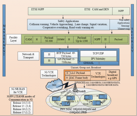
This study designed a 5G V2V communication architecture based on the ETSI V2V communication architecture. The architecture is made up of five levels. Starting from the top is the facility layer which consists of the OSI model's three top levels (Sessional, Presentation, and Application) with equivalent roles which are followed by the network and transport layer, and down is the access layer. 3GPP has revised the access layer's physical and data link layers to meet the 5G V2X QoS criterion. The other two layers are management and security. Figure 7 illustrates the 5G V2V architecture.
Figure 7. 5G-V2V Communication architecture
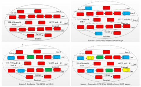
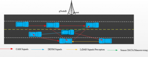
Figure 8. 5G V2V scenarios with VUEs broadcasting CAM, CAM+DENM, CAM+DENM+LiDAR, and CAM+DENM+LiDAR+sensor data
4.2.1 LTE-V2X and 5G V2X services
V2X services are divided into two categories: safety and non-safety. The safety use case considers broadcasting two messages for collective awareness and environmental notice. In LTE-V2X, only safety messages CAM and DENM are broadcast among the VUEs. The evolution of the advanced driving use cases in version 15 for NR V2X services, and 5G V2X services have expanded beyond the transmission of CAM and DENM. Various sensing devices requiring a high data rate are incorporated into the vehicles to support NR V2X services. Hence, the sidelink 5G V2V channel is expected to distribute collective awareness, cooperative perception, and cooperative maneuvering services. In 5G V2V communication, the quality of the sidelink channel may be harmed if these messages are delivered without a proper estimate of the channel capacity. The services exchange over the channel comprises the safety message CAM, which is expected from each VUE that enters the system, the exchange of CAM plus the DENM message, the exchange of CAM, DENM, and LIDAR contents, and the exchange of CAM, DENM, LIDAR, and sensor DATA for cooperative maneuvering. Providing these services across the V2V sidelink radio channel is a huge hurdle to overcome if LLRC is achieved. Figure 8 depicts the scenario of the four categories of NR V2X and LTE V2X services expected in the 5G NR network.
4.2.2 System capacity estimation
System capacity is defined as the ability of a system to accommodate changes in traffic demand while maintaining QoS requirements [41]. It can also be defined as the number of UEs that can simultaneously transmit and receive a message within the stipulated latency limit in a communication environment [52]. Capacity is one of the system performance characteristics of a mobile wireless network that ensures the availability of spectrum resources for seamless communication among the network's device users. Capacity estimation is done about uncontrollable external changes. Changes in demand or use, a shift in spatial traffic patterns related to mobility, infrastructure loss and degradation, and changes in the price and availability of spectrum resources are all factors that influence system behavior [53].
Latency reduction by establishing a latency model to minimize latency in scheduling can improve system throughput and is considered one of the approaches to capacity estimation. Addressing mobility is another procedure, where a mobility model can be developed within the 5G V2X system based on channel quality and the velocity/speed at which the VUEs move. A connection of links to system-level simulation can be utilized to analyze the capacity of the sidelink V2V channel for LOS and NLOS communication together with the deployment parameters as specified in 3GPP Release 15 for LTE V2V and NR V2V. Another method that can be used to estimate the capacity of the V2V sidelink channel is proposed by Ghanbarisabagh et al. [54]. They used a parametrized model’s motion and trajectory estimation for nonlinear least mean squares under-sample image sequences. 5G technology enablers such as network slicing and efficient machine learning techniques are used to address the V2V capacity challenges.
(1) 5G V2V Channel Capacity estimation for safety and non-safety services
Since the arrival of vehicles into the system follows a Poisson point process, in this section we use a Markov Queuing theory (M/G/1) and ITU-R parameters to obtain the mathematical approximation model of the mean throughput and mean delay requirement that is used to estimate the capacity limit of the 5G-V2X network. The arrival and service of the vehicles are based on the safety and advanced driving 5G V2V services.
(a) System Model
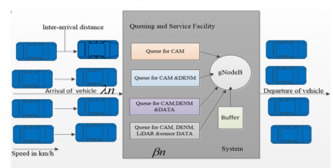
The system model assumes that the arrival of the vehicles follows a Poisson point process (PPP) as described in TS 22.18 with an arrival rate λn. The vehicles enter the system to be served and leave within a specific time interval. The time it takes for a vehicle to be served (the time it spends in the system) depends on the scheduling process. It is also assumed that the system has infinite capacity so that each vehicle that arrives in the system can be served appropriately with available resources and no delay associated with the queuing exist. Figure 9 depicts a scenario where each VUE is allocated unlimited resources for the four services (CAM, DENM, LiDAR, sensor DATA) until the services are completed.
Figure 9. Depiction of a scenario where each VUE is allocated unlimited resources for the four services (CAM, DENM, LiDAR, sensor DATA) until the services are completed
Figure 10. Derivation of a cubic polynomial function to obtain the throughput limit of the system with arrivals and departures
In Figure 9, vehicles arrive at the 5G V2X system and request resource allocation to transmit a CAM message or CAM plus data. The request is forwarded to the gNB using a physical uplink shared channel (PUSCH). The gNB allocates the resources using the physical downlink shared channel (PDSCH) via the downlink control information (DCI) format based on the VUEs buffer status. After each vehicle is allocated a resource, the transmission of the messages is performed via the PSSCH known as V2V sidelink communication. The service of the vehicles is assumed to be a non-pre-emptive priority, meaning the vehicle currently receiving service is not interrupted but complete before the service of the newly arrived vehicle with a higher priority packet begins. The scheduling discipline is assumed to be first come, first serve (FCFS), and the service duration βndepends on the packet size Sn and the data transmission rate Cn. Based on the above assumptions, the approximate model for the Markovian Poisson arrival general service and one server (M\G\1) queue is developed as a function of the first and second moments of the vehicle arrivals and the service times. Then, a cubic polynomial function is derived to obtain the throughput limit of the system with arrivals and departures, as shown in Figure 10.
Figure 10 illustrates how the vehicles randomly arrive at the service facility and serve by the gNB with M/G/1 scheduling. The symbols and abbreviations used in the system and analytical models are defined in Table 2.
Table 2. Symbols and abbreviations used in modeling
|
Symbols |
Definitions |
|
M/G/1 |
Poison arrival, general service, and single server |
|
λn |
Mean arrival rate |
|
Si |
Service time |
|
Sn |
Mean packet size |
|
Si(2) |
The second moment of service time |
|
βn |
Mean service time |
|
Wn |
Mean waiting time |
|
Dn |
Mean packet delay |
|
Cn |
Channel capacity |
|
N |
Total number of packets generated by the services |
|
n |
number of services n = 1, 2, ... N with N = 4 |
|
Tn |
Offered base traffic |
(b) Analytical model for analysis of PSSCH capacity limit
The packet arrival or packet generation rate λn (packet/s) of the 5G V2X messages can be obtained from Eq. (3).
$\lambda_{n}=\frac{T_{n}}{S_{n}} 1 \leq n \leq \mathrm{N}$ (3)
The total arrival rate is the sum of the aggregated arrival of all the data packets transmitted.
$\lambda_{\mathrm{At}}=\sum_{n=1}^{\mathrm{N}} \lambda_{n}$ (4)
N is the number of packets generated by the 5G V2V UEs, and λAt is the total arrival rate of the data packets. Let C (RB/slot) be the channel capacity, i.e., the number of RBs that can be transmitted per unit time then, the mean service time $\beta_{n}$ (s/packet), and the second moment $\beta_{n}^{2}$ (s2/packet2) of the service time for an RB packet for a use case n, is given by
$\beta_{n}=\frac{S_{n}}{C_{n}}$ (5)
$\beta_{n}^{(2)}=\frac{S_{n}^{(2)}}{C_{n}^{2}}$ (6)
The system capacity required to determine the mean delay of the service n can be obtained based on the priority level of the service that requires the highest capacity to ensure the quality of service (QoS) support. The overall system capacity is
$C=\max \left(C_{1}, C_{2}, \ldots, C_{N}\right), 1 \leq N \leq 4$ (7)
The needed capacity for the entire system is determined by the system capacity of the service with the highest rate. The mean packet delay Dn is the sum of the queuing delay (waiting time) Wn and the mean service time βn.
$D_{n}=W_{n}+\beta_{n}$ (8)
But,
$w_{n}=\frac{\sum_{i=1}^{N p s} \lambda_{i} \beta_{i}^{(2)}}{2\left(1-\sum_{i=1}^{n-1} \lambda_{i} \beta_{i}\right)\left(1-\sum_{i=1}^{n} \lambda_{i} \beta_{i}\right)} n \leq i \leq N \mathrm{ps}$ (9)
Substituting Eq. (9) in Eq. (8)
$D_{n}=\frac{\sum_{i=i}^{\mathrm{N}} \lambda_{i} S_{i}^{(2)}}{2\left(C_{n}-\sum_{i=1}^{n} \lambda_{i} S_{i}\right)\left(C_{n}-\sum_{i=1}^{n-1} \lambda_{i} S_{i}\right)}+\frac{S_{n}}{C_{n}}$ (10)
$D_{n}-\frac{S_{n}}{C_{n}}=\frac{\sum_{i=1}^{\mathrm{N}} \lambda_{i} S_{i}^{(2)}}{2\left(C_{n}-\sum_{i=1}^{n} \lambda_{i} S_{i}\right)\left(C_{n}-\sum_{i=1}^{n-1} \lambda_{i} S_{i}\right)}$ (11)
Eq. (11) can further be solved to obtain the roots of the equation with at least one value satisfying the required system capacity i.e.
$\sum_{i=1}^{n} \lambda_{i} S_{i}<C_{n}$
Eq. (11) is expressed as
$2\left(C_{n} D_{n}-S_{n}\right)\left(C_{n}-\sum_{i=1}^{n-1} \lambda_{i} S_{i}\right)\left(C_{n}-\sum_{i=1}^{n} \lambda_{i} S_{i}\right)$
$-C_{n} \sum_{i=1}^{N} \lambda_{i} S_{i}^{(2)}=0$ (12)
Through expansion, Eq. (12) becomes
$\begin{aligned} C_{n}^{3} D_{n}-2 C_{n}{ }^{2}\left[D_{n}\left(\sum_{I=1}^{n-1} \lambda_{i} S_{i}\right)\left(\sum_{i=1}^{n} \lambda_{i} S_{i}\right)+S_{n}\right] \\+& 2 C_{n}\left[D_{n}\left(\sum_{i=1}^{n-1} \lambda_{i} S_{i}\right)\left(\sum_{i=1}^{n} \lambda_{i} S_{i}\right)\right.\\ &\left.+S_{n}\left(\sum_{i=1}^{n-1} \lambda_{i} S_{i}+\sum_{i=1}^{n} \lambda_{i} S_{i}\right)\right] \\ &-\sum_{i=1}^{N p s} \lambda_{i} S_{i}^{(2)} 2 \\ &-S_{n}\left(\sum_{i=1}^{n-1} \lambda_{i} S_{i}\right)\left(\sum_{i=1}^{n} \lambda_{i} S_{i}\right)=0 \end{aligned}$ (13)
$a_{n} x^{3}+b_{n} x^{2}+d_{n} x+e_{n}$ (14)
$a_{n}=2 D_{n}$ (15a)
$b_{n}=-2\left[D_{n}\left(\sum_{i=1}^{n-1} \lambda_{i} S_{i}\right)\left(\sum_{i=1}^{n} \lambda_{i} S_{i}\right)+S_{n}\right]$ (15b)
$\begin{aligned} d_{n}=2\left[D_{n}\left(\sum_{i=1}^{n-1} \lambda_{i} S_{i}\right)\left(\sum_{i=1}^{n} \lambda_{i} S_{i}\right)\right.\\ &\left.+S_{n}\left(\sum_{i=1}^{n-1} \lambda_{i} S_{i}+\sum_{i=1}^{n} \lambda_{i} S_{i}\right)\right] \\ &-\sum_{i=1}^{N} \lambda_{i} S_{i}^{(2)} \end{aligned}$ (15c)
$e_{n}=-2 S_{n}\left(\sum_{i=1}^{n-1} \lambda_{i} S_{i}\right)\left(\sum_{i=1}^{n} \lambda_{i} S_{i}\right)$ (15d)
To determine the roots of Eq. (13), the coefficients are compared with the general form of a cubic polynomial Eq. (14).
Since the equation has real number root x , then
$\sum_{i=1}^{n} \lambda_{i} S_{i}<C_{n}$
5.1 Network slicing concept
5G systems are being launched to address societal, commercial, and institutional issues from a new perspective and provide consumers with services and demands that will be available in 2020 and beyond. The requirement to support several vertical industries, such as manufacturing, automobiles, healthcare, energy, education, media, and entertainment, is one of the primary drivers of 5G [55]. Because the verticals have various service and functional requirements, a network slice is a crucial enabler for these services. It can only be possible if the functions are positioned in a desired and precise position. Network slicing is a method of sharing resources between two or more logical networks built on top of a single physical infrastructure. Network slicing, as described in 3GPP version 15 [56, 57], is based on three technology enablers, namely (1) Software-Defined Network (SDN), (2) Network Function Virtualizer (NFV), and (3) Mobile Edge Computing (MEC), and it allows multiple virtual networks to share a single physical infrastructure. Khan et al. [58] defined network slicing as achieving an end-to-end (E2E) view from the mobile edge to the core network, including front-haul (FH) and backhaul (BH) portions of the CN. Barakabitze et al. [59] defined NS as a collection of critical 5G capabilities that enable data processing to match the specified customer demand. As one of the 5G enablers, network slicing is required to integrate with other 5G enablers to provide business customers with connection and data evaluation assigned to a specific business requirement based on a Service Level Agreement (SLA).
Sparks et al. [60] defined network slicing as a logical (virtual) network customized to serve specific business purposes or customer requirements regarding an end-to-end portion of network resources needed to satisfy the service class' specific performance and economic needs or customer application. Network slicing is a significant 5G enabler since it creates several logical networks on top of shared physical infrastructure [61]. NS is viewed differently in different standards, white papers, and articles. In general, network slicing is the aggregation of related network resources (efficiently assigned over resource pools) and network functions that enable vertical industries to interact and achieve system Quality of Service (QoS) while delivering user Quality of Experience (QoE). Network slicing refers to the effective allocation, sharing, and utilization of resources to improve the global economy in the 5G era. Network slicing allows small and large businesses to collaborate and improve the quality of their operations by dividing network services (e.g.one industry can own the infrastructure, another the network, and so on).
5.2 V2X network slicing for the autonomous use case
Network slicing can effectively increase the performance of vehicle-to-everything (V2X) communication in the context of the 5G V2X service demand. In NS diverse use cases can be multiplexed across a single physical infrastructure, with each use case obtaining an effective slice allocation. Various verticals can be assigned to independent slices or even share the same slice without causing harm to their company. Unlike other 5G use cases, V2X does not allow direct mapping of services onto the reference slices [62]. The requirements for V2X slices are determined by the type of service that the VUE is anticipated to provide. In an autonomous driving use case, a 5G V2X user is expected to communicate safety alerts and share advanced driving information with the surrounding vehicles via unicast, group cast, and broadcast packet handling processes [63]. Services are assigned to the NS according to their categories to minimize slicing overhead caused by additional data requests from the VUEs. As a result, NS may be used to avoid or alleviate system/channel congestion after a network's capacity limit has been identified.
5.3 Network slicing enabling technologies
Network slicing can be accomplished using three enabling technologies, as explained in the following:
• Network Function Virtualization (NFV): A network function virtualization (NFV) is a significant 5G technology enabler that supports network slicing. NFV allows network functions to be reconfigured and network resources to be virtualized using appropriate software with each service having a predetermined function chain in the prior design deployment. However, with NFV, many functions can be provided by a single service slice [64]. As networks are made up of network functions, each network slice requires a flexible allocation of dedicated resources. Network Functions Virtualization (NFV) technology has been identified as a viable enabler for bringing 5G network slicing to life [59]. The concept of network slicing is implemented in three steps, namely (1) design, (2) instantiation, and (3) operation. NFV is the ideal technology for the life cycle management and orchestration of network functions. It plays important role in allowing operators to slice a single physical network into virtual networks according to a specific service level agreement (SLA). It is also required to provide the necessary assistance in automating the adaptation of the slice's resources to the appropriate quality of service and performance level. An example of a network slice is the autonomous driving slice which requires ultra-low latency and extra high reliability to exchange safety and non-safety messages with networks and other vehicles. To provide services with low latency, the autonomous slice necessitates the deployment of one of the services closer to the access nodes, and some network functions must be instantiated several times on various physical servers for improved reliability [59].
• Mobile Edge Computing: This is another network slicing enabler that enhances network speed by offering service to cell edge users; the cloud server is deployed at the network's edge to do this. When communication, computation, and storage infrastructures are combined under the same control, edge computing delivers V2X services with real-time applications. For network slicing, MEC has been investigated in several studies [65-70].
• Software-Defined Network (SDN): SDN splits the control plane from the user plane and uses logically centralized intelligence networking to simplify network management, introduce programmability, and open network access [71, 72]. SDN is a 5G enabler that enables service-oriented adaptation, scalability, flexibility, and resilience, all of which are vital aspects of effective network slicing.
5.4 V2X RAN slicing
To Slice V2X RAN, the functionalities are expected from the slice. The RAT, RAN architecture, type of application (e.g., V2V, V2I), interface parameter configuration, and the policy of allocating resources to the slice must be considered while slicing a network. The main slicer of a network, along with accurate construction and placement of network operations, is proper radio resource allocation. Albonda and Perez-Romero [73] defined RAN slicing as "an efficient design and resource allocation to satisfy the slicing functionality and achieve the intended objectives." A straightforward and accurate algorithm allocates slices to the UEs while slicing a network. When NS covers the core, transport, and RAN, it is considered end-to-end. An efficient machine learning algorithm can slice a network.
Many researchers have presented an NS-based communication model for a vehicle network with heterogeneous traffic (eMBB and URLLC) and an OFDMA resource allocation scheme [74-76]. Khan et al. [77] address the vehicular communication problem by developing a network clustering and slicing algorithm that divided vehicles into different clusters and assigned slice leaders to each cluster.
Outage probability, resource allocation, and interference control are used to assess the network's performance. Diverse studies have been conducted using network slicing from various angles to tackle the difficulty of radio resource management. Service-oriented resource management in a spatial reuse-based C-V2X network was proposed [78-81]. They introduced a novel C-V2X framework based on network slicing and spatial reuse to support URLLC eMBB services. Liang et al. [82] developed a network slicing model for various V2X services to maximize resource utilization. Similarly, to improve the system's QoS, Tang et al. [83] suggested Adaptive virtual resource allocation in 5G network slicing by employing a restricted Markov Decision Process (MDP) with a slice-based virtual resource scheduling scheme and NOMA technology.
Various studies have been conducted using network slicing from various angles to tackle the problem of radio resource management. Other studies combine machine learning and network slice with efficient resource allocation algorithms. In Feng et al. [67] and Gu et al. [84], slicing RAN was proposed by dividing the physical infrastructure into slices to provide different processing and communication functions. Albonda and Pérez-Romero [85] developed an efficient RAN slicing strategy for Heterogeneous Network (HN) eMBB and V2X, based on a machine learning offline reinforcement learning technique with a heuristic algorithm that allocates resources to the slices. A deep learning-based reinforcement learning technique is used to reduce rising complexity and maximize resource efficiency in 5G V2X networks [86-89].
6.1 Discussion
3GPP enhances the performance of vehicle-to-vehicle (V2V) communication by introducing a cellular V2V communication in release 14. 25 use cases for V2X are established in release 15 to enable vehicles to exchange not only safety messages but also non-safety messages through cooperative sensing and cooperative maneuvering within the 5G V2X network. Following the advancement of C V2X technology with different sensing and actuator devices estimating the capacity limit of the V2V channel will ensure better communications. Different studies are conducted on the physical layer enhancement of the ETSI communication architecture (Figure 7) to enable effective sidelink communication for C V2X services. Lien et al. [31] reviewed 3GPP NR sidelink transmission towards 5G V2X concerning the physical layer structure, physical channel, power control, etc. Peisa et al. [33] present an overview of the 5G evolution for release 16 and release 17. However, they did not consider the capacity of the NR sidelink channel in their review as vehicle safety relies on how the V2V channel transmits the allocated services. Safety in V2Vcommunication focuses more on how much data rate is capable of providing smooth running of the 5G V2X network.
While we emphasize estimating the capacity of the 5G V2V channel, other works are trying to know the capacity of the 5G access network (gNB) for seamless resource allocation. Kanavos et al. [12] evaluate the gNB capacity to support V2X use cases for a 5G frame with three different vehicle densities and within the same geographical area in an urban environment. But studying the capacity of PSSCH is of much significance as the vehicles can obtain their spectrum resources even in the absence of the infrastructure. In this work, we consider designing the 5G V2X ETSI/3GPP combined architecture that we couldn’t come across in the literature.
In release 18 standards 3GPP has the mission of introducing futuristic concepts such as Artificial Intelligence (AI)/Machine learning (ML), full-duplex operation, and network power-saving. With these efforts, Hyundai motors introduce a Meta-mobility also called Mobility of Things (MoT) to allow inanimate things from small objects to community spaces to gain mobility at ultra-high-speed (or beyond normal mobility) using the company's robotic technologies. These robotic technologies can operate with the help of LiDAR, RADAR, and sensor cameras. Among the 5G V2X applications that will enjoy MoT include Advanced driving and platooning. Increasing more services to the V2X network and incorporating the vehicles with different sensor devices necessitates an increase in capacity to ensure safe and reliable communications among the vehicle users. According to the International Mobile Telecommunication (IMT), the 5G communication data rate should be in the order of gigabit/s.
6.2 Conclusion
This paper has represented Sidelink communication as the method of exchanging messages between VUEs of the same RAT and those of different RATs using the PC5 interface. Some of the physical layer enhancements introduced by 3GPP for V2V ETSI communication architecture are presented together with resource selection and resource allocation procedures in LTE V2X and NR V2X networks. Sidelink V2V communication improves safety among the VUEs, but V2V communication requires proper resource allocation and effective resource management. Radio Resource Management (RRM) plays a vital role in mobile wireless vehicular systems. Still, it faces many challenges in the context of 5G V2V communication due to the stringent QoS requirements of the system and the high demand for data rates. It is observed in the literature that different studies were conducted using 5G enablers (NS and ML) to maximize the system capacity interns of spectrum utilization. However, the studies emphasized the CAM message, with few taking DENM into account. To this end, we proposed designing an efficient resource allocation scheme for NS using ML to ensure proper resource management for 5G V2X services (CAM, DENM, LIDAR, and sensor DATA).
Multiple slices can be created for different services with an efficient ML algorithm to allocate resources to each slice, monitor the slice condition, manage interference among the slices, and much more. We also recommend more research on V2V spectrum estimation to oppose the FCC Notice of Proposed RuleMaking (NPRM) and to request additional spectrum allocation for V2V services. A 40MHz band is essential for the proper operation of the 5G V2X network, according to Qualcomm news on March 31, 2019; however, more research is needed to support or oppose the proposal. Our future research will focus on executing the formulated queueing model of section 4.2.2 to estimate the capacity limit of the 5G V2X network for the four categorized V2X use cases (CAM, DENM, LiDAR, and sensor DATA).
[1] Bhoi, S.K., Khilar, P.M. (2014). Vehicular communication: A survey. IET Networks, 3(3): 204-217. https://doi.org/10.1049/iet-net.2013.0065
[2] Campolo, C., Molinaro, A., Berthet, A.O., Vinel, A. (2019). On latency and reliability of road hazard warnings over the cellular V2X sidelink interface. IEEE Communications Letters, 23(11): 2135-2138. https://doi.org/10.1109/lcomm.2019.2931686
[3] Karyemsetty, N., Kumar, K.R. (2020). Road safety: An accident prevention using an intelligent vehicular network. International Journal of Safety and Security Engineering, 10(5): 631-638. https://doi.org/10.18280/ijsse.100507
[4] ETSI. (2021). Service requirements for the 5G system. Technical Report TS 122 261. Version 16.14.0. Sophia Antipolis Cedex - FRANCE.
[5] 3GPP. (2015). Evolved universal terrestrial radio access (E-UTRA) overall description. Technical Specification. TS 136300. Version 12.4.0. Sophia Antipolis Cedex-FRANCE.
[6] 3GPP. (2014). Universal mobile telecommunication system LTE; Proximity Services Stage 2 Release 12 V.12.2.0. Technical Report. TS-123 303. Sophia Antipolis Cedex - FRANCE.
[7] Jameel, F., Hamid, Z., Jabeen, F., Zeadally, S., Javed, M.A. (2018). A survey of device-to-device communications: Research issues and challenges. IEEE Communications Surveys & Tutorials, 20(3): 21332168. https://doi.org/10.1109/COMST.2018.2828120
[8] Ganesan, K., Lohr, J., Mallick, P.B., Kunz, A., Kuchibhotla, R. (2020). Nr sidelink design overview for advanced V2X Service. IEEE Internet of Things Magazine, 3(1): 26-30. https://doi.org/10.1109/IOTM.0001.1900071
[9] Ligo, A., M Peha, J., (2019). Spectrum for V2X: Allocation and Sharing. IEEE Transaction, 5(3): 768-779. https://doi.org/10.1109/tccn.2019.2916026
[10] Kuciemba, S., Timcho, T., McLaughlin, K., Perry, F., Bezzina, D. (2021). Evaluation and synthesis of connected vehicle communication technologies, No. NCHRP Project 23-10.
[11] ETSI. (2011). Intelligent Transport Systems (ITS); Vehicular Communications; Basic Set of Applications; Part 2: Technical Specification TS 102 637-2, V1.2.1 Sophia Antipolis Cedex - FRANCE.
[12] Kanavos, A., Fragkos, D., Kaloxylos, A. (2021). V2X communication over cellular networks: Capabilities and challenges. Telecom, 2(1): 1-26. https://doi.org/10.3390/telecom2010001
[13] Kanumalli, S.S., Anuradha, C., Murty, P.S.R.C. (2018). An efficient method for detection of Sybil attackers in IOV. Advances in Modelling and Analysis A, 61(1): 5-8. https://doi.org/10.18280/ama_b.610102
[14] Airault, S., Jamet, O. (1995). Détection et restitution automatique du réseau routier sur des images aériennes. Traitement du Signal, 12(2): 189-200.
[15] 3GPP. (2016). LTE; Evolved Universal Terrestrial Radio Access (E-UTRA) Study on V2X Services; Services provided by the physical layer. Technical Specification. TS 36.885 V.14.2.0. Sophia Antipolis Cedex - FRANCE.
[16] Molina-Masegosa, R., Gozalvez, J., Sepulcre, M. (2018). Configuration of the C-V2X mode 4 sidelink PC5 interface for vehicular communication. In 2018 14th International Conference on Mobile Ad-Hoc and Sensor Networks (MSN), pp. 43-48. https://doi.org/10.1109/MSN.2018.00014
[17] 3GPP. (2018). Third Generation Partnership Project; Technical Specification Group Radio Access Network; Study on Evaluation Methodology of new Vehicle-to-Everything V2X use cases for LTE and NR V.15.0.0. Technical Report TS-37.885. Sophia Antipolis Cedex - FRANCE.
[18] 3GPP. (2018). Third Generation Partnership Project; Technical Specification Group Radio Access Network; Evolved Universal Terrestrial Radio Access Control (RRC); Protocol specification V.14.7.0. Technical Report TS-36.331. Sophia Antipolis Cedex - FRANCE.
[19] Toghi, B., Saifuddin, M., Fallah, Y.P., Mughal, M. (2019). Analysis of distributed congestion control in cellular vehicle-to-everything networks. IEEE 90th Vehicular Technology Conference (VTC2019-Fall), pp. 1-7. https://doi.org/10.1109/VTCFall.2019.8891335
[20] Molina-Masegosa, R., Gozalvez, J. (2017). System level evaluation of LTE-V2V mode 4 communications and its distributed scheduling. In 2017 IEEE 85th Vehicular Technology Conference (VTC Spring), pp. 1-5. https://doi.org/10.1109/VTCSpring.2017.8108463
[21] Fodor, G., Do, H., Ashraf, S.A., Blasco, R., Sun,W., Belleschi, M., Hu, L. (2019). Supporting Enhanced Vehicle-to-Everything Services by LTE release 15 systems. IEEE Communications Standards Magazine, 3(1): 26-33. https://10.1109/MCOMSTD.2019.1800049
[22] 3GPP. (2018). LTE; Evolved Universal Terrestrial Radio Access (E-UTRA); Medium Access Control (MAC) protocol specification V.15.2.0. Technical Report TS-36.321. Sophia Antipolis Cedex - FRANCE.
[23] Gonzalez-Martín, M., Sepulcre, M., Molina-Masegosa, R., Gozalvez, J. (2018). Analytical models of the performance of C-V2X mode 4 vehicular communications. IEEE Transactions on Vehicular Technology, 68(2): 1155-1166. https://doi.org/10.1109/TVT.201 8.2888704
[24] Garcia, M.H.C., Molina-Galan, A., Boban, M., Gozalvez, J., Coll-Perales, B., Şahin, T., Kousaridas, A. (2021). A tutorial on 5G NR V2X communications. IEEE Communications Surveys & Tutorials, 23(3): 1972-2026. https://doi.org/10.1109/COMST.2021.3057017
[25] Hegde, A., Festag, A. (2019). Mode Switching Strategies in Cellular-V2X. IFAC-PapersOnLine, 52(8): 221-226. https://doi.org/ 10.1016/j.ifacol.2019.08.052
[26] Ghosh, A., Maeder, A., Baker, M., Chandramouli, D. (2019). 5G Evolution: A view on 5G cellular technology beyond 3GPP Release 15. IEEE Access, 7(1): 127639-127651. https://doi.org/10.1109/ACCESS.2019.2939938
[27] 3GPP. (2020). 5G; NR; Overall Description; Stage-2 V.15.8.0. Technical Report TR 38.300. Sophia Antipolis Cedex- FRANCE.
[28] 3GPP. (2020). 5G; Architecture enhancements for 5G System to Support Vehicle-to-Everything (V2X) Services 5G; V.16.3.0. Technical Report TR 23.287. Sophia Antipolis Cedex - FRANCE.
[29] Ganesan, K., Mallick, P.B., Löhr, J., Karampatsis, D., Kunz, A. (2019). 5G V2X architecture and radio aspects. In 2019 IEEE Conference on Standards for Communications and Networking (CSCN), pp. 1-6. https://doi.org/10.1109/CSCN.2019.8931319
[30] 3GPP. (2017). LTE; Architecture Enhancements for V2X Services V.14.2.0. Technical Specification TS 23.285 Release 14. Sophia Antipolis Cedex - FRANCE.
[31] Lien, S.Y., Deng, D.J., Lin, C.C., Tsai, H.L., Chen, T., Guo, C., Cheng, S.M. ( 2020). 3GPP NR sidelink transmissions toward 5G V2X. IEEE Access, 8(1): 35368-35382. https://doi.org/10.1109/ACCESS.2020.2973706
[32] Nardini, G., Stea, G., Virdis, A., Sabella, D. (2020). Simu5G: A system-level simulator for 5G networks. In Simultech, pp. 68-80.
[33] Peisa, J., Persson, P., Parkvall, S., Dahlman, E., Grovlen, A., Hoymann, C., Gerstenberger, D. (2020). 5G evolution: 3GPP releases 16 & 17 overview. Ericsson Technology Review, 6: 2-13.
[34] 3GPP. (2018). Technical Specification Group Services and System Aspects; Study on enhancement of 3GPP Support for 5G V2X Services. Technical Report 3GPP TS-22.886 V.16.2.0. Sophia Antipolis Cedex - FRANCE.
[35] 3GPP. (2020). 5G; Service Requirements for Enhanced V2X Scenarios. Technical Report TR-22.186 V.16.2.0. Sophia Antipolis Cedex - FRANCE.
[36] Voigt, C., Plechinger, J., Ag, A. (2019). 5G Automotive Association, pioneering the transformation in the automotive industry. https://5g-ppp.eu/wp-content/uploads/2019/01/2.-5GAA-FLAMENT-5G-vertical-WS_120219.pdf.
[37] Rao, J., Vrzic, S. (2018). Packet duplication for URLLC in 5G: Architectural enhancements and performance analysis. IEEE Network, 32(2): 32-40. https://doi.org/10.1109/MNET.2018.1700227
[38] Loussaief, F., Marouane, H., Koubaa, H., Zarai, F. (2020). Radio resource management for vehicular communication via cellular device to device links: review and challenges. Telecommunication Systems, 73(4): 607-635. https://doi.org/10.1007/s11235-019-00644-x
[39] 3GPP. (2020). LTE; 5G; Overall description of Radio Access Network (RAN) Aspects for Vehicle-to-Everything (V2X) based on LTE and NR V.16.0.0. Technical Specification TS 37.985 Release 16. Sophia Antipolis Cedex - FRANCE.
[40] 3GPP. (2020). TS 36. Evolved Universal Terrestrial Radio Access (E-UTRA); Physical layer procedures. Technical Specification TS 36.213 version 10.3.0. Sophia Antipolis Cedex - FRANCE.
[41] Zhang, X., Peng, M., Yan, S., Sun, Y. (2019). Deep-reinforcement-learning-based mode selection and resource allocation for cellular V2X communications. IEEE Internet of Things Journal, 7(7): 6380-6391. https://doi.org/10.1109/JIOT.2019.2962715
[42] 3GPP. (2020). 5G; NR; Physical layer procedures for control. Technical Specification 3GPP TS -TR 38.213. Sophia Antipolis Cedex - FRANCE.
[43] Han, J., Cui, Q., Yang, C., Tao, X. (2014). Bipartite matching approach to optimal resource allocation in device to device underlaying cellular network. Electronics Letters, 50(3): 212-214. https://doi.org/10.1049/el.2013.2378
[44] Ullah, H., Nair, N.G., Moore, A., Nugent, C., Muschamp, P., Cuevas, M. (2019). 5G communication: an overview of vehicle-to-everything, drones, and healthcare use-cases. IEEE Access, 7: 37251-37268. https://doi.org/10.1109/ACCESS.2019.2905347
[45] Chen, Q., Wu, T.T., Fang, M. (2013). Detecting local community structures in complex networks based on local degree central nodes. Physica A: Statistical Mechanics and Its Applications, 392(3): 529-537. https://doi.org/10.1016/j.physa.2012.09.012
[46] Yang, Y., Quan, Q., Li, J., Peng, T., Wang, W. (2013). Network assisted mode selection in multi-cell for D2D communication underlaying LTE-A system. In 2013 15th IEEE International Conference on Communication Technology, pp. 110-114. https://doi.org/10.1109/ICCT.2013.6820356
[47] Alam, M., Yang, D., Huq, K. (2016). Towards 5G: Context aware resource allocation for energy saving. Springer Journal of Signal Processing, 83(2): 279-291. https://doi.org/10.1007/s11265-015-1061-x
[48] Albonda, H.D.R., Pérez-Romero, J. (2018). An efficient mode selection for improving resource utilization in sidelink V2X cellular networks. In 2018 IEEE 23rd International Workshop on Computer Aided Modeling and Design of Communication Links and Networks (CAMAD), pp. 1-6. https://doi.org/10.1109/CAMAD.2018.8514958
[49] Nabil, A., Kaur, K., Dietrich, C., Marojevic, V. (2018). Performance analysis of sensing-based semi-persistent scheduling in C-V2X networks. In 2018 IEEE 88th Vehicular Technology Conference (VTC-Fall), pp. 1-5. https://doi.org/10.1109/VTCFall.2018.8690600
[50] Ahmadi, S. (2019). 5G NR: Architecture, Technology, Implementation, and Operation of 3GPP New Radio Standards. Academic Press.
[51] Nardini, G., Virdis, A., Campolo, C., Molinaro, A., Stea, G. (2018). Cellular-V2X communications for platooning: Design and evaluation. Sensors, 18(5): 1527. https://doi.org/10.3390/s18051527
[52] Chen, M., Hao, Y., Lin, K., Yuan, Z., Hu, L. (2018). Label-less learning for traffic control in an edge network. IEEE Network, 32(6): 8-14. https://doi.org/10.1109/MNET.2018.1800110
[53] Mongrain, R., Cyr, M., Bertrand, M., Magnin, I. (2001). Parametrized models motion estimation using non linear least mean squares. Traitement du Signal, 18(5-6): 369-382.
[54] Ghanbarisabagh, M., Vetharatnam, G., Giacoumidis, E., Momeni Malayer, S. (2019). Capacity improvement in 5G networks using femtocell. Wireless Personal Communications, 105(3): 1027-1038. https://doi.org/10.1007/s11277-019-06134-2
[55] Ordonez-Lucena, J., Ameigeiras, P., Lopez, D., Ramos-Munoz, J.J., Lorca, J., Folgueira, J. (2017). Network slicing for 5G with SDN/NFV: Concepts, architectures, and challenges. IEEE Communications Magazine, 55(5): 80-87. https://doi.org/ 10.1109/MCOM.2017.1600935
[56] 3GPP. (2018). 5G; System Architecture for the 5G System. Technical Specification TS 23.501. V15.2.0. Sophia Antipolis Cedex – FRANCE.
[57] Mademann, F. (2018). The 5G system architecture. Journal of ICT Standardization, 6(1): 77-86. https://doi.org/10.13052/jicts2245-800x.615
[58] Khan, A., Minokuchi, A., Tsubouchi, A., Kunito, G., Iwashina, S. (2018). Technology and standards accelerating 5G commercialization. IEICE Trans. Commun., E102B(3): 410-417. https://doi.org/10.1587/transcom.2018NVI0002
[59] Barakabitze, A.A., Ahmad, A., Mijumbi, R., Hines, A. (2020). 5G network slicing using SDN and NFV: A survey of taxonomy, architectures and future challenges. Computer Networks, 167(2020): 1-40. https://doi.org/10.1016/j.comnet.2019.106984
[60] Spark, K., Marvin, S., Lyan, N., et al. (2016). 5G network slicing. FCC Technological Advisory Council 5G IoT Working Group, USA.
[61] GSA, Nokia, Huawei, Ericsson. (2017). 5G Network Slicing for Vertical Industries, GSA.
[62] Campolo, C., Fontes, R.D., Molinaro, A., Rothenberg, C. E., Iera, A. (2018). Slicing on the road: Enabling the automotive vertical through 5G network softwarization. Sensors (Switzerland), 18(12): 1-17. https://doi.org/10.3390/s18124435
[63] Condoluci, M., Mahmoodi, T. (2018). Softwarization and virtualization in 5G mobile networks: Benefits, trends and challenges. Computer Networks, 146: 65-84. https://doi.org.1016/j.comnet.2018.09.005
[64] Nencioni, G., Garroppo, R.G., Gonzalez, A.J., Helvik, B.E., Procissi, G. (2018). Orchestration and control in software-defined 5G networks: Research challenges. Wireless Communications and Mobile Computing. https://doi.org/ 10.1155/2018/6923867
[65] Cominardi, L., Deiss, T., Filippou, M., Sciancalepore, V., Giust, F., Sabella, D. (2020). MEC support for network slicing: Status and limitations from a standardization viewpoint. IEEE Communications Standards Magazine, 4(2): 22-30. https://doi.org/10.1109/MCOMSTD.001.1900046
[66] D'Oro, S., Bonati, L., Restuccia, F., Polese, M., Zorzi, M., Melodia, T. (2020). Sl-EDGE: Network slicing at the edge. In Proceedings of the Twenty-First International Symposium on Theory, Algorithmic Foundations, and Protocol Design for Mobile Networks and Mobile Computing, pp. 1-10. https://doi.org/10.1145/3397166.3409133
[67] Feng, J., Pei, Q., Yu, F. R., Chu, X., Du, J., Zhu, L. (2020). Dynamic network slicing and resource allocation in mobile edge computing systems. IEEE Transactions on Vehicular Technology, 69(7): 7863-7878. https://doi.org/10.1109/TVT.2020.2992607
[68] Husain, S.S., Kunz, A., Prasad, A., Pateromichelakis, E., Samdanis, K. (2019). Ultra-high reliable 5G V2X communications. IEEE Communications Standards Magazine, 3(2): 46-52. https://doi.org/10.1109/MCOMSTD.2019.1900008
[69] Ksentini A., Frangoudis, P.A. (2020). Toward slicing-enabled multi-access edge computing in 5G. IEEE Network, 34(2): 99-105. https://doi.org/10.1109/MNET.001.1900261
[70] Shen, X., Gao, J., Wu, W., et al. (2020). AI-assisted network-slicing based next-generation wireless networks. IEEE Open Journal of Vehicular Technology, 1: 45-66. https://doi.org/10.1109/OJVT.2020.2965100
[71] Tsietsi, M., Chindeka, T., Terzoli, A. (2017). An IMS subscriber location function for OpenBaton—A standards based MANO environment. In 2017 IEEE AFRICON, pp. 894-899. https://doi.org/10.1109/AFRCON.2017.8095600
[72] Open Networking Foundation. (2016). Applying SDN architecture to 5G slicing. Onf Tr-526, (1): 1-19.
[73] Albonda, H.D.R., Pérez-Romero, J. (2019). An efficient RAN slicing strategy for a heterogeneous network with eMBB and V2X services. IEEE Access, 7: 44771-44782. https://doi.org/10.1109/ACCESS.2019.2908306
[74] Oladejo, S.O., Falowo, O.E. (2020). Latency-aware dynamic resource allocation scheme for multi-tier 5G network: A network slicing-multitenancy scenario. IEEE Access, 8: 74834-74852. https://doi.org/10.1109/ACCESS.2020.2988710
[75] Popovski, P., Trillingsgaard, K.F., Simeone, O., Durisi, G. (2018). 5G wireless network slicing for eMBB, URLLC, and mMTC: A communication-theoretic view. Ieee Access, 6: 55765-55779. https://doi.org/10.1109/ACCESS.2018.2872781
[76] Lee, Y.L., Loo, J., Chuah, T.C., Wang, L.C. (2018). Dynamic network slicing for multitenant heterogeneous cloud radio access networks. IEEE Transactions on Wireless Communications, 17(4): 2146-2161. https://doi.org/10.1109/TWC.2017.2789294
[77] Khan, H., Luoto, P., Samarakoon, S., Bennis, M., Latva-Aho, M. (2021). Network slicing for vehicular communication. Transactions on Emerging Telecommunications Technologies, 32(1): e3652. https://doi.org/10.1002/ett.3652
[78] Liu, C.F., Bennis, M. (2018). Ultra-reliable and low-latency vehicular transmission: An extreme value theory approach. IEEE Communications Letters, 22(6): 1292-1295. https://doi.org/10.1109/LCOMM.2018.2828407
[79] Wang, Y., Zhai, E., Hu, J., Chen, Z. (2010). Claper: Recommend classical papers to beginners. In 2010 Seventh International Conference on Fuzzy Systems and Knowledge Discovery, 6: 2777-2781. https://doi.org/10.1109/FSKD.2010.5569227
[80] Sun, Y., Peng, M., Mao, S., Yan, S. (2019). Hierarchical radio resource allocation for network slicing in fog radio access networks. IEEE Transactions on Vehicular Technology, 68(4): 3866-3881. https://doi.org/10.1109/TVT.2019.2896586
[81] Baumgartner, A., Bauschert, T., Koster, A.M., Reddy, V.S. (2017). Optimisation models for robust and survivable network slice design: A comparative analysis. In GLOBECOM 2017-2017 IEEE Global Communications Conference, pp. 1-7. https://doi.org/10.1109/GLOCOM.2017.8254073
[82] Liang, L., Ye, H., Li, G.Y. (2018). Toward intelligent vehicular networks: A machine learning framework. IEEE Internet of Things Journal, 6(1): 124-135. https://doi.org/10.1109/JIOT.2018.2872122
[83] Tang, L., Tan, Q.I., Shi, Y., Wang, C., Chen, Q. (2018). Adaptive virtual resource allocation in 5G network slicing using constrained Markov decision process. IEEE Access, 6(1): 61184-61195. https://doi.org/10.1109/ACCESS.2018.2876544
[84] Gu, R., Zhang, S., Ji, Y., Yan, Z. (2018). Network slicing and efficient ONU migration for reliable communications in converged vehicular and fixed access network. Vehicular Communications, 11: 57-67. https://doi.org/10.1016/j.vehcom.2018.01.003
[85] Albonda, H.D.R., Pérez-Romero, J. (2019). Reinforcement learning-based radio access network slicing for a 5G system with support for cellular V2X. In International Conference on Cognitive Radio Oriented Wireless Networks, pp. 262-276. https://doi.org/10.1007/978-3-030-25748-4_20
[86] Gao, J., Khandaker, M.R., Tariq, F., Wong, K.K., Khan, R.T. (2019). Deep neural network based resource allocation for V2X communications. In 2019 IEEE 90th Vehicular Technology Conference (VTC2019-Fall), pp. 1-5. https://doi.org/10.1109/VTCFall.2019.8891446
[87] Sattiraju, R., Weinand, A., Schotten, H.D. (2019). Channel estimation in C-V2X using deep learning. In 2019 IEEE International Conference on Advanced Networks and Telecommunications Systems (ANTS), pp. 1-5. https://doi.org/10.1109/ANTS47819.2019.9117972
[88] Kulkarni, A., Seetharam, A., Ramesh, A., Herath, J.D. (2019). Deepchannel: Wireless channel quality prediction using deep learning. IEEE Transactions on Vehicular Technology, 69(1): 443-456. https://doi.org/10.1109/TVT.2019.2949954
[89] Ma, H., Li, S., Zhang, E., Lv, Z., Hu, J., Wei, X. (2020). Cooperative autonomous driving oriented MEC-aided 5g-v2x: Prototype system design, field tests and ai-based optimization tools. IEEE Access, 8: 54288-54302. https://doi.org/10.1109/ACCESS.2020.2981463