Onkar Singh* | Gaitry Arora | Vinod Kumar Sharma
OPEN ACCESS
Heliostat-based solar thermal power system consisting of a combination of the Brayton cycle, Rankine cycle, and organic Rankine cycle is a potential option for harnessing solar energy for power generation. Among different options for improving the performance of solarized triple combined cycle the option of introducing intercooling and reheating in the gas turbine cycle and utilizing the waste heat for augmenting the power output needs investigation. Present study considers a solarized triple combined cycle with intercooling and reheating in gas turbines while using the heat rejected in intercooling in heat recovery vapour generator and heat recovery steam generator separately in two different arrangements. A comparison of two distinct cycle arrangements has been carried out based on Ist law and IInd law of thermodynamics with the help of thermodynamic parameters. Results show that triple combined cycle having intercooling heat used in heat recovery vapour generator offers maximum energy efficiency of 63.54% at 8 CPR & 300K ambient temperature and maximum exergetic efficiency of 38.37% at 14 CPR & 300 K. While the use of intercooling heat in heat recovery steam generator offers maximum energy and exergetic efficiency of 64.15% and 39.72% respectively at 16 CPR & 300 K ambient temperature.
central receiver, triple combined cycle, R1233zd(E), HRSG, HRVG, energy- exergy analysis
As the energy demand is increasing, consumption of the fossil fuel is also increasing which in turns increases the environmental hazards as the burning of fossil fuel results in carbon production and other gases which is responsible for global warming and also there is cost which is associated with fossil fuel such as transporting cost, Extracting fossil fuel cost. Further, in view of continued reliance on fossil fuel driven power plants for meeting the power needs, fossil fuels are nearing depletion. Therefore, researchers are moving in the direction to find a sustainable source of energy which is renewable energy resources. The European Commission has an energy strategy of replacing fossil-fuel by increasing utilization of renewable energy resources and cutting down 40% of greenhouse gas emissions and targeting that at least 32% must be shared by renewable energy resources by 2030 [1]. Solar energy is the most promising and secured renewable source of energy needing detailed thermodynamic analysis of cycle based on it. The study of the thermodynamic cycle of a renewable energy source based power plant cannot be completed until the analysis is done by both the first law and second law of thermodynamics as the first law only gives the quantitative value of energy but the second law gives the qualitative value of energy. Exergy efficiency and destruction investigation provide more insight towards ideality. Thus, the exergy investigation serves as a worthwhile tool for enhancing the energy efficiency of large scale thermal energy systems [2].
The literature review shows that the Sanjay [3] carried out the energy and exergy analysis of combined cycle systems with different cycles, operating as a bottoming cycle, and observed that maximum steam is to be generated in case of triple pressure HRSG. Chandra and Kaushik [4] performed the energy and exergy analysis of the closed Brayton cycle with a regenerator, reheater, intercooler, and found that even with zero energy loss in reheater there occurs some exergy losses. Carcasciand and Winchler [5] presented that many times industrial waste has the potential to run low-temperature cycles for that they combined organic Rankine cycle with a gas turbine for converting waste into power as this low-temperature heat discharged can't be utilized with traditional Rankine Cycle. Amiralipoura and Kouhikamali [6] parametrically studied the effect of steam extraction on net power for the amount of water production and concluded that this will lead to a reduction in net power by 5.5 kW. Idrissa and Boulama [7] evaluated the exergy destruction by applying the advanced exergy analysis of components in a closed Brayton cycle power plant and found that the most exergy which is destructed in the combustion chamber is endogenous and unavoidable and further stated that varying the combustion temperature leads to reduce the destruction of the plant. Khan and Tlili [8] did a parametric comparison between steam and gas bottoming cycles and showed that the steam bottoming cycle having higher net-work output as a comparison to the gas bottoming cycle. Yang et al. [9] proposed a four-step investigation process wherein first, it checked the applicability of R1233zd(E) as an alternative to R245fa and compared R1233zd(E) to R245fa experimentally with a conclusion that R1233zd(E) is not only environment friendly but it also leads in thermal efficiency and power output by 3.8% and 4.5% respectively. Coco-Enríquez et al. [10] studied four different configurations based on the s-CO2 Brayton cycle with reheating and intercooling and found that recuperation in the Brayton cycle leads to higher thermal efficiency compared to the Rankine cycle and combining the s-CO2 to the dual-loop solar field is beneficial in terms of cost of the solar field and thermal efficiency than to coupling of the dual loop solar field to Rankine cycle. Adibhatla and Kaushik [11] explored energy and exergy analysis of the conventional natural gas-fired having steam generation solar field and found that in DSG ISCCPP components the lowest exergetic efficiency is 27.4% for a solar field.
Rovira et al. [12] showed that when solar input is given for saturated steam generation then the highest thermal to electrical efficiency of 44.6% is achieved and the lowest efficiency of 33.5% is obtained when used for water preheating too. Kelly et al. [13] suggested the highly effective method for converting the thermal energy of solar into electricity by feed water extraction from the HRSG’seconomizer and producing saturated steam, and returning steam for superheating and reheating in HRSG by the exhaust of gas turbine. Saghafifarand Gadalla [14] investigated the Maisotsenko bottoming cycle power plant hybridization using a heliostat field collector. Maisotsenko gas turbine cycle also known as M-cycle is a recently proposed bottoming cycle. Kong et al. [15] concluded that the increase in pinch value leads to lowering the second law efficiency for which it used three different heat sources such as hot water, saturated steam, and combined hot water/saturated steam to supply heat at the ORC evaporator and with the heat source temperature varying from 80-110°C, the difference in pinch temperature of the heat source and the evaporating temperature was in the range of 1-10°C. Sachdeva and Singh [22] performed the theoretical analysis based on both the Ist & IInd law of thermodynamics to assess the performance parameters for identifying optimal conditions of the combined cycle configuration. Choi et al. [23] compared the efficiency of the triple combined cycle with carbon captured or without carbon captured and concluded that with carbon capture the 5% less efficiency is achieved and this will decrease with capture increasing rate.
The present paper deals with energy and exergy analysis of a solarized triple combined cycle with intercooling and reheating in the GT cycle combined with steam Rankine cycle and organic Rankine cycle for power with no carbon emission. The system consists of an intercooled-reheat type topping Brayton cycle and two bottoming cycles out of which one is steam run steam Rankine cycle and the other is an organic fluid run organic Rankine cycle. The air run GT cycle employs two stages intercooled compression and reheating during expansion while utilizing the solar energy collected through heliostats and used through a molten salt heat exchanger. During intercooling, the heat rejected in intercooler is utilized in the heat recovery vapour generator (HRVG) in one of the arrangements while in the other arrangement this heat ejected during intercooling is used in heat recovery steam generator (HRSG). Thus, two distinct triple combined cycle arrangements have been analyzed and compared. The considered combined cycle configurations have been analyzed using thermodynamic modeling based on the first law of thermodynamics and the second law of thermodynamics. The results obtained have been analyzed and presented herein to underline the effect of waste heat utilization on triple combined cycle performance which will pave way for power sector professionals to evolve suitable efficient arrangements using solar energy.
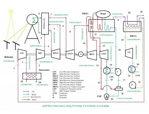
Figure 1(a). Solarized triple combined cycle with Intercooling and reheating using Intercooling heat rejection in HRVG
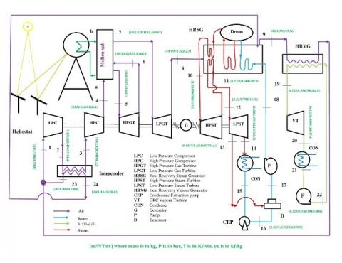
Figure 1(b). Solarized triple combined cycle with Intercooling and reheating using Intercooling heat rejection in HRSG
Figures 1(a) and 1(b) detail the schematic of the intercooled reheat type gas turbine cycle along with steam Rankine and organic Rankine cycle for power generation consisting of a heliostat field to power the intercooled-reheat type gas-turbine cycle. The heliostat field reflects solar radiation to a receiver. Here a mixture of KNO3 (40 wt. %) & NaNO3 (60 wt. %) [24, 25] is used as a salt in the molten salt heat exchanger. Air compressed from state 1 to state 2 in LPC and then goes to the intercooler for being cooled before subsequent compression. The heat rejected by the compressed air in intercooler is used in HRVG as shown in figure 1a and in HRSG as shown in figure 1b. Considering perfect intercooling the air at state 23 which is at ambient temperature enters the intercooler. The compressed air then enters a molten salt heat exchanger, where it is heated using the heat from the molten salt. The air at high pressure and temperature is then expanded in the high-pressure gas turbine up to state 6 from where it again goes to the molten salt heat exchanger for getting reheated and gains the same temperature equivalent to that at state 5. After reheating the further expansion occurs in the LPGT up to state 8 from where the air passes to HRSG, where it transfers its heat for steam generation from the water delivered by the feed pump of the reheat steam Rankine cycle at state 18. The high-temperature superheated steam leaving HRSG enters HPST at state 10 and expands to 11 from where it goes to HRSG and again attains the temperature similar to that at state 10. The reheated steam enters LPST at state 12 and expands up to state 14 with a steam bleeding at state 13 for deaeration. The condensate is then pumped by the feed pump from state 17 to 18 and again enters the HRSG for steam generation. The air leaving HRSG at state 9 goes to HRVG and exits at state 1. The low-temperature heat available with air passing through HRVG is used for evaporating refrigerantR1233zd(E) besides intercooler heat in the organic Rankine cycle. The high-pressure refrigerant from state 19 expands to 20 and goes to the ORC condenser. The condensate moves from state 20 to 21 and is again sent to HRVG for getting the working fluid for the ORC vapour turbine.
The energy and exergy analysis of the proposed intercooled-reheat type gas turbine, steam turbine, and organic Rankine cycle are done using energy balance and exergy balance of each component by thermodynamic modeling through the C program.
Following assumption considered during analysis are listed below:
These are some generalized equation for the components of the considered cycle which are explained below:
Mass balance across components:
$\sum m_{\text {inlet }}=\sum m_{\text {outlet }}$
Energy balance across components:
$\sum E_{\text {inlet }}=\sum E_{\text {outlet }}$
Exergy balance across components:
$\sum E x_{\text {inlet }}=\sum E x_{\text {outlet }}+E_{x_{d}}$
Enthalpy in kJ/kg at each state can be calculated as:
$\mathrm{h}=\int C_{p} \cdot \mathrm{dt}$
Exergy in kJ/kg at each state is given as:-
ex=(h-ho)-To.(s-so)
3.1 Heliostat field, central receiver
Energy balance for heliostat field is given by-
$\mathrm{Q}_{\mathrm{max}}=\mathrm{Q}_{\mathrm{rec}}+\mathrm{Q}_{\text {lost }}$ (1)
where,
$Q_{\max }=I . A_{h f}$ (2)
Qmax is the incident solar radiation that will be divided into two parts in which one goes to receiver (solar isolation) and other is lost due to some environmental factors(Irreversibility). After accounting radiation energy losses, energy efficiency of heliostat (ηh) is given by-
ηh=Qrec/Qmax (3)
Exergy equation related to solar irradiation is -
Exergy_solar=Qmax.(1-(To/Tsun)) (4)
Energy balance for receiver is given by-
Qrec =Qrec, abs+ Qrec, loss (5)
where, Qrec, abs is the energy that is absorbed by the receiver and Qrec, loss is the energy that is lost due to emissive, reflective, convective, and conductive losses.
Taking into account receiver efficiency-
ηrec=Qrec, abs/Qrec. (6)
3.2 Air property model
Here Brayton cycle having working fluid as air having a molar composition of 0.21 O2 and 79 N2. The specific heat of air is a function of temperature expressed as [16]-
Cp(T), kJ/kg-K=0.98964-5.344x10-5T+3.39x10-7T2-1.344x10-10T3 (7)
3.3 Topping cycle
Here Topping cycle considered is the Brayton cycle with air its working fluid which is powered by solar energy with a provision of no carbon emission. Intercooling and Reheating are taken.
Considering polytropic efficiency of compressor the temperature at the exit of the compressor is obtained as-
$\frac{\mathrm{T}_{2}}{\mathrm{~T}_{1}}=\left(\frac{\mathrm{P}_{2}}{\mathrm{P}_{1}}\right)^{\left[\frac{\gamma-1}{\gamma \cdot \eta p o l y_{-} c}\right]}$ (8)
Considering Intercooling, the air at state 2 is cooled to the temperature of ambient by exchanging its heat into HRVG to the organic working fluid.
T3=T1 (9)
Energy balance across compressor can be obtained as-
m1.h1+Wc=m2.h2 (10)
Exergy balance across compressor can be obtained as-
m1.ex1+Wc=m2.ex2+Exd,c (11)
Second law efficiency of the compressor is given as-
$\eta_{I I, C o m p}=\frac{e x_{2}-e x_{1}}{\frac{W_{C}}{m_{a i r}}}$ (12)
Energy balance across intercooler for both layout1a and layout 1b is given by-
m2.h2+ m23.h23= m3.h3+m24.h24 (13)
Considering polytropic efficiency for gas turbine, the exit temperature of the turbine after the expansion is obtained as-
$\frac{T_{5}}{T_{6}}=\left(\frac{P_{5}}{P_{6}}\right)^{\left[\frac{\gamma-1}{\gamma}\right] \cdot \eta_{\text {poly_turb }}}$ (14)
Considering perfect reheating,
T5=T7 (15)
Turbine inlet temperature is given by-
Qmax.ηh.ηr =mair.(h5-h4)+mair.(h7-h6) (16)
Energy balance across Gas turbine
m5.h5=m6.h6+Wgt (17)
Exergy balance for Gas turbine-
m5.ex5=m6.ex6+Wgt+ Exd,turb (18)
Second law efficiency of the turbine is given as-
$\eta_{I I, t u r b}=\frac{\frac{W_{g t}}{m_{a i r}}}{e x_{5}-e x_{6}}$ (19)
Thus the net work output of the topping cycle is,
Wnet=Wgt-Wc (20)
Gas turbine cycle’s energy efficiency is expressed by-
ηgt=Wnet/Qmax (21)
3.4 Heat recovery steam generator
When intercooling heat is used in HRSG as shown in figure 1b, the exhaust of GT cycle at state 8 goes to HRSG for exchanging its heat with water delivered by feed pump at state 18 for steam generation and exit at state 9.
The energy balance across HRSG when intercooling heat is used in HRSG given by-
$\begin{array}{c}
\epsilon_{H R S G} \cdot\left(\mathrm{m}_{8} \cdot \mathrm{h}_{8}+\mathrm{m}_{24} \cdot \mathrm{h}_{24}-\mathrm{m}_{9} \cdot \mathrm{h}_{9}\right)=\left(\mathrm{m}_{10} \cdot \mathrm{h}_{10}+\mathrm{m}_{12} \cdot \mathrm{h}_{12}\right)- \\
\left(\mathrm{m}_{11} \cdot \mathrm{h}_{11+} \mathrm{m}_{18} \cdot \mathrm{h}_{18}\right)
\end{array}$ (22)
The energy balance across HRSG when intercooling heat is used in HRVG given by-
$\begin{array}{c}
\epsilon_{H R S G} \cdot\left(\mathrm{m}_{8} \cdot \mathrm{h}_{8}-\mathrm{m}_{9} \cdot \mathrm{h}_{9}\right)=\mathrm{m}_{10} \cdot \mathrm{h}_{10}+\mathrm{m}_{12} \cdot \mathrm{h}_{12}- \\
\left(\mathrm{m}_{11} \cdot \mathrm{h}_{11+} \mathrm{m}_{18} \cdot \mathrm{h}_{18}\right)
\end{array}$ (23)
Exergy balance across HRSG when intercooling heat is used in HRSG is given by-
(m8.ex8)+(m11.ex11) +(m18.ex18)+(m24.ex24)=(m9.ex9)+(m10.ex10)+(m12.ex12)+Exd,HRSG (24)
Exergy balance across HRSG when intercooling heat is used in HRVG is given by-
(m8.ex8)+(m11.ex11)+(m18.ex18)=(m9.ex9)+(m10.ex10)+(m12.ex12)+Exd,HRSG (25)
Second law efficiency of HRSG is-
$\eta_{I I, H R S G}=1-\left(\mathrm{Exd}, \mathrm{HRSG} / \mathrm{av}, \mathrm{H}_{\mathrm{RSG}}\right)$ (26)
For Figure 1(a)
av,HRSG=(ex8- ex9).mair (27)
For Figure 1(b)
av,HRSG=(ex8+ex24-ex9).mair (28)
3.5 Bottoming cycle
There are two bottoming cycles. One is the steam run steam Rankine cycle (SRC) and the other is an organic fluid run organic Rankine cycle (ORC).
3.5.1 SRC
Here a reheat Rankine cycle with steam bleeding for deaeration is combined with a topping cycle through HRSG.
(1) HPST
Energy balance in high pressure steam turbine is given by-
m10.h10=m11.h11+WHPST (29)
Considering the isentropic efficiency of the turbine
$\eta_{i s e n, H P S T}=\left(\mathrm{h}_{10}-\mathrm{h}_{11}\right) /\left(\mathrm{h}_{10}-\mathrm{h}_{11, \mathrm{is}}\right)$ (30)
Exergy balance for High Pressure steam turbine-
m10.ex10=m11.ex11+WHPST+Exd,HPST (31)
Exd,HPST is exergy destruction across high pressure steam turbine.
Second law efficiency of high pressure steam turbine:
$\eta_{\mathrm{IL}, \mathrm{HPST}}=\frac{\frac{W_{H P S T}}{m_{\text {steam }}}}{e x_{10}-e x_{11}}$ (32)
where, ηII,HPST is the second law efficiency of HPST
(2) LPST
Energy balance in low pressure steam turbine is given by-
m12.h12=m13.h13+m14.h14+WLPST (33)
m13=fr.m12 (34)
m14=(1-fr).m12 (35)
Perfect reheating is considered, so the temperatures at state 10 and 12 are same.
T10=T12 (36)
Taking isentropic efficiency of the turbine
$\eta_{i s e n, L P S T}=\left(\mathrm{h}_{12}-\mathrm{h}_{13}\right) /\left(\mathrm{h}_{12}-\mathrm{h}_{13 \mathrm{is}}\right)$ (37)
Exergy balance for low pressure steam turbine
$m12.ex12=m13.ex13+m14.ex14+WLPST+Exd,LPST$ (38)
Exd,LPST is exergy destruction across low pressure steam turbine
Second law efficiency of low pressure steam turbine-
$\eta_{\mathrm{II}, \mathrm{LPST}}=\frac{\frac{W_{L P S T}}{m_{\text {steam }}}}{e x_{12}-e x_{14}}$ (39)
(3) Condenser
Energy balance for condenser is given by-
m14.h14=m15.h15+Qcond (40)
Exergy balance across condenser
$\mathrm{m}_{14} \cdot \mathrm{ex}_{14}=\mathrm{m}_{15} \cdot \mathrm{ex}_{15+} \mathrm{Q}_{\text {cond }}\left(1-\frac{T_{o}}{T_{\text {space }}}\right)+\mathrm{Exd}_{\text {,cond }}$ (41)
(4) Pump
Energy balance for pump yields,
m17.h17+Wpump=m18.h18 (42)
$\mathrm{W}_{\text {pump }}=\mathrm{m}_{15} .\left(\mathrm{h}_{18}-\mathrm{h}_{17}\right)=\int v \cdot d p$ (43)
(5) Deaerator
Energy balance across deaerator is given by-
m13.h13+m15.h15=m17.h17 (44)
(6) Condensate extraction pump
Energy balance for pump yields,
m15.h15+WCEP=m16.h16 ((45)
Energy efficiency of steam Rankine cycle is given as -
$\eta_{\mathrm{I}, \mathrm{SRC}=} \frac{W_{H P S T}+W_{L P S T^{-}} W_{p u m p}-W_{C E P}}{\left(h_{8}-h_{9}\right) \cdot m_{a i r}}$ (46)
(7) Heat recovery vapour generator
The exhaust air at state 9 goes to HRVG and exits at state 1. During state 9 to state 1 the exhaust heat is used in the evaporation of the organic fluid R1233zd(E).
The energy balance across HRVG when intercooling heat is used in HRVG given by-
$\epsilon_{\mathrm{HRVG}}\left(\mathrm{m}_{9} \cdot \mathrm{h}_{9}+\mathrm{m}_{24} \cdot \mathrm{h}_{24}-\mathrm{m}_{25} \cdot \mathrm{h}_{25}-\mathrm{m}_{1} \cdot \mathrm{h}_{1}\right)=\mathrm{m}_{\text {oxc } \cdot}\left(\mathrm{h}_{19}-\mathrm{h}_{22}\right)$ (47)
The energy balance across HRVG when intercooling heat is used in HRSG given by-
$\epsilon_{\mathrm{HRVG}}\left(\mathrm{m}_{9} \cdot \mathrm{h}_{9}-\mathrm{m}_{1} \cdot \mathrm{h}_{1}\right)=\mathrm{m}_{\text {orc. }}\left(\mathrm{h}_{19}-\mathrm{h}_{22}\right)$ (48)
Exergy balance across HRVG when intercooling heat is used in HRVG is given by-
m9.ex9+m24.ex24+m22.ex22=m1.ex1+m19.ex19+m25.ex25+Exd,HRVG (49)
Exergy balance across HRVG when intercooling heat is used in HRSG is given by-
m9.ex9+m22.ex22=m1.ex1+m19.ex19+Exd,HRVG (50)
Second law efficiency of HRVG is-
$\eta_{I I, H R V G}=1-(\mathrm{Exd}, \mathrm{HRVG} / \mathrm{av}, \mathrm{HRVG})$ (51)
For layout 1(a)
av,HRVG= (ex9+ex24- ex25-ex1).mair (52)
For Figure 1(b)
av,HRVG= (ex9-ex1).mair (53)
3.5.2 Organic rankine cycle
Organic Rankine cycle is the second bottoming cycle which is a low temperature cycle work on organic fluid R1233zd(E).
(1) ORC vapor turbine
Energy balance across ORC vapor turbine is given as-
m19.h19=m20.h20+W,orct (54)
Exergy balance across ORC vapor turbine
m19.ex19=m20.ex20+W,orct+Exd,orct (55)
Second law efficiency of ORC vapor turbine is given as-
$\eta_{\mathrm{II}, \text { orct }}=\frac{\frac{W_{\text {orct }}}{m_{\text {orc }}}}{e x_{19}-e x_{20}}$ (56)
(2) ORC condenser
Conservation of energy across ORC condenser
m20.h20=m21.h21+Qcond,orc (57)
Exergy balance across orc condenser
m20.ex20=m21.ex21+Qcond,orc+ Exdcond,orc (58)
(3) ORC pump
Conservation of energy across ORC Pump
m21.h21=m22.h22+Worc,pump (59)
Energy efficiency of Organic Rankine cycle is given as-
$\eta_{\mathrm{I}, \mathrm{ORC}}=\frac{W_{\text {orct }}-W_{\text {orc }, \text { pump }}}{\left(h_{9}-h_{1}\right) \cdot m_{\text {air }}}$ (60)
3.6 Overall cycle
The net-work output from the considered combined cycle comprises of the work output from intercooled-reheat type Brayton cycle, reheat SRC, and ORC along with the heat in the condensers of the bottoming cycles.
W,overall=$\begin{array}{rl}
W_{g t}+W_{H P S T}+W & W_{L P S T}+W_{\text {orct }}+Q_{\text {cond }} \\
& +Q_{\text {cond,orc }}-W_{c}-W_{p}-W_{C E P} \\
& -w_{\text {Orc,pump }}
\end{array}$ (61)
Overall cycle efficiency is given as-
$\begin{array}{c}
W_{g t}+W_{H P S T}+W_{L P S T}+W_{\text {orct }}+Q_{\text {cond }} \\
\eta_{I, \text { overall }}=\frac{+Q_{\text {cond,orc }}-W_{c}-W_{p}-W_{C E P}-w_{\text {Orc,pump }}}{Q_{\max }}
\end{array}$ (62)
Overall exergy efficiency is given as-
$\begin{array}{r}
W_{g t}+w_{H P S T}+W_{L P S T}+w_{\text {orct }}+Q_{\text {cond }} \cdot\left(1-\frac{T 0}{\text { Tspace }}\right) \\
\eta_{\text {II }, \text { exergy }}=\frac{+Q_{\text {cond,orc. }}\left(1-\frac{\text { To }}{\text { Tspace }}\right)-W_{c}-W_{p}-W_{C E P}-W_{\text {orc,pump }}}{Q_{\max } \cdot\left(1-\frac{T 0}{\text { Tspace }}\right)}
\end{array}$ (63)
Results are obtained from the thermodynamic modeling and computer simulation of the air-powered solarized intercooled-reheat GT cycle combined with the steam Rankine cycle and organic Rankine cycle for carbon-free power based on the input parameters given below in Table 1, REFPROP, and e-Thermo.
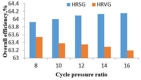
Figure 2 details the comparison of energy efficiency of the overall cycle for the arrangements shown in figure 1(a) and figure1(b) at 300K ambient temperature. Here it is seen that the energy efficiency of the overall cycle is more when the intercooling heat is utilized in HRSG and increases with increasing CPR and attains a maximum value of 64.15% at 16 CPR. And, when intercooling heat is utilized in HRVG, then the overall efficiency is seen to decrease with increasing CPR and achieves a maximum value of 63.54% at 8 CPR.
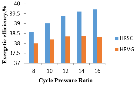
Fig. 3 depicts that the overall exergetic efficiency of the triple combined cycle is maximum when intercooling heat is utilized in HRSG and the exergetic efficiency increases with increasing cycle pressure ratio to offer the maximum value of 39.72% at 16 CPR. Whereas in the case when intercooling heat is utilized in HRVG then with increasing CPR, the exergetic efficiency increases till 14 CPR and attains the maximum value of 38.37% and then decreases.
Table 1. Input parameters [9, 17-21]
|
Parameters |
Symbol, Unit |
Value |
|
Sun temperature |
Tsun, K |
5778 |
|
Solar Irradiation |
I, W/m2 |
1000 |
|
Heliostat Field Area |
Ahf, m2 |
16666 |
|
Concentration Ratio |
CR |
1200 |
|
Heliostat Efficiency |
ηh, % |
75 |
|
Receiver Efficiency |
ηr , % |
80 |
|
Polytropic Efficiency of Compressor |
$\eta_{\text {poly_c }}$, % |
80 |
|
Polytropic efficiency of Turbine |
$\eta_{\text {poly_turb }}$, % |
80 |
|
Ambient Temperature |
T1, K |
290, 295, 300 |
|
Ambient Pressure |
P1, bar |
1 |
|
Cycle Pressure Ratio |
- |
8,10,12,14,16,18,20 |
|
Effectiveness of HRSG |
$\epsilon_{H R S G}$,% |
95 |
|
Steam generation pressure |
PHPST, bar |
90 |
|
Steam generation temperature |
THPST, K |
755 |
|
Low pressure steam turbine pressure |
PLPST, bar |
5 |
|
Isentropic efficiency of steam turbine |
$\eta_{\text {isen, HPST }}$, % |
87 |
|
Bleeding pressure |
Pbleed, bar |
1.2 |
|
Condenser pressure |
Pcon, bar |
0.07 |
|
Effectiveness of HRVG |
$\epsilon_{H R V G}$,% |
85 |
|
Organic fluid |
R1233zd(E) |
|
|
Evaporation Temperature of Vapor turbine |
Tevap., K |
388 |
|
Isentropic efficiency of Vapor turbine |
$\eta_{\text {isen }}$, ORC ,% |
85 |
|
Dead state temperature |
To, K |
288.15 |
|
Dead state pressure |
Po, bar |
1 |
Figure 2. Comparing the energy efficiency of the overall cycle with Intercooling heat using in HRSG and in HRVG at 300K ambient temperature
Figure 4 shows the comparison of overall work output in kJ/kg of air for two different layouts shown in Figure 1(a) and 1(b). It shows that when intercooler heat is utilized in HRSG, the overall work output of the triple combined cycle increases with increasing CPR and it attains the maximum value of 1069.9 kJ/kg of air at 16 CPR. Further, when the intercooler heat is utilized in HRVG, the overall work output of the triple combined cycle decreases with increasing CPR and offers the maximum value of 1058.99 kJ/kg of air at 8 CPR.
Figures 5a, 5b are the graphical representations of overall work output’s variation with cycle pressure ratio at different ambient temperatures. Figure 5a shows the overall work output of the cycle when intercooling heat is utilized in HRSG. It is evident that at the higher ambient temperature of 300 K and at a higher CPR of 16, the overall work output is seen to be maximum with a value of 1069.9kJ/kg of air. Figure 5b shows the overall work output of the cycle when intercooling heat is utilized in HRVG. It shows, that at the lower CPR of 8 and higher ambient temperature 300 K, it yields the maximum value of 1058.99 kJ/kg of air.
Figure 3. Comparing exergetic efficiency of the overall cycle with intercooling heat used in HRSG and in HRVG
Figure 4. Comparison of overall work while using intercooled heat in HRSG and separately in HRVG
Figure 5a. Overall work output of cycle in kJ/kg of air using intercooled heat in HRSG at different ambient temperature with cycle pressure ratio
Figure 5b. Overall work output of cycle in kJ/kg of air using intercooled heat in HRVG at different ambient temperature with cycle pressure ratio
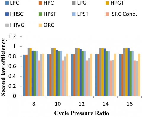
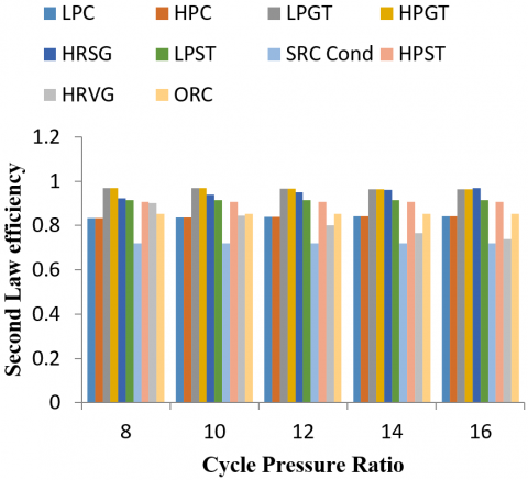
Figure 6a. Second law efficiency variation in different components of the combined cycle for Figure 1(a)(HRVG) at 300 K ambient temperature
Figure 6b. Second law efficiency variation in different components of the combined cycle for Figure 1(a)(HRVG) at 295 K ambient temperature
Figure 6c. Second law efficiency variation in different components of combined cycle for Figure 1(a)(HRVG) at 290 K ambient temperature
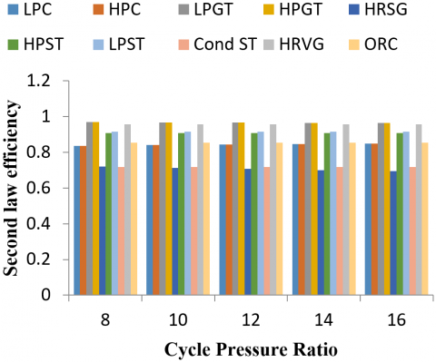
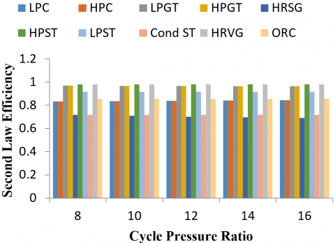
Figure 7a. Second law efficiency variation in different components of the combined cycle for layout given in figure 1(b) (HRSG) at 300 K ambient temperature
Figure 7b. Second law efficiency variation in different components of the combined cycle for layout given in figure 1(b) (HRSG) at 295 K ambient temperature
Figure 7c. Second law efficiency variation in different components of the combined cycle for layout given in figure 1(b) (HRSG) at 290 K ambient temperature
Figure 6a, 6b, and 6c show second law efficiency variation in different components for Figure 1(a) at 300 K, 295 K, and 290 K ambient temperatures respectively. Since intercooling is considered perfect hence the second law of efficiency for LPC and HPC has the same values of 0.8384, 0.8359, and 0.8333 respectively for 300 K, 295 K, and 290 K ambient temperatures. It is seen that with increasing CPR, the value of second law efficiency for the compressor is increasing and lies in the range of 0.8384 to 0.8326 and with the consideration of perfect reheating the second law of efficiency for LPGT and HPGT have the same values of 0.9703, 0.9683 and 0.9681 at 300 K, 295 K and 290 K ambient temperatures respectively. Also, with increasing CPR the value of second law efficiency is decreasing and lies in the range of 0.9703 to 0.9639. The second law efficiency for HRSG is 0.9185, 0.9205, and 0.9225 respectively for 300 K, 295 K, and 290 K ambient temperatures graphically. It is observed that the second law of efficiency increases with increasing cycle pressure ratio and variation lies in the range of 0.9185, 0.9332, 0.9451, 0.9554, and 0.9644 for 300 K ambient temperature, 0.9205, 0.9355, 0.9468, 0.9577, 0.9677 for 295 K ambient temperature and 0.9225, 0.9383, 0.9502, 0.9604 and 0.9695 for 290 K ambient temperature. For HRVG, the second law efficiency is 0.7934, 0.7474, 0.7117, 0.6835, and 0.6601 at 300 K ambient temperature i.e. decreasing with increasing CPR and with decreasing ambient temperature it is increasing and attains the value of 0.844 at 295K and 0.9019 at 290K ambient temperature. The second law efficiency of HPST is 0.9081 and the second law efficiency of LPST is 0.9149, the second law efficiency of condenser is 0.7186 and for ORC turbine is 0.8529 where all values remain constant with CPR and ambient temperature.
Figure 7a, 7b, and 7c show second law efficiency variation in different components for layout depicted in figure 1(a) at 300 K, 295 K, and 290 K ambient temperatures respectively. Since intercooling is considered perfect hence the second law of efficiency for LPC and HPC has the same values of 0.8384, 0.8359, and 0.8333 respectively for 300 K 295 K and 290 K ambient temperatures. It is evident that with increasing CPR, the value of the second law efficiency for the compressor is increasing from 0.8384 to 0.8326, and with the consideration of perfect reheating the second law of efficiency for LPGT and HPGT have the same values of 0.9703, 0.9683, and 0.9681 respectively at 300 K, 295 K, and 290 K ambient temperature. Also, with increasing CPR the value of second law efficiency is decreasing and lies in the range of 0.9703 to 0.9639. The second law efficiency for HRSG is 0.726, 0.7214 and 0.716 respectively for 300 K, 295 K and 290 K ambient temperatures graphically it is represented that with increasing cycle pressure ratio second law of efficiency is decreasing and variation lies in the range of 0.726, 0.7191, 0.7126, 0.7065, and 0.7010 for 300 K ambient temperature, 0.7214, 0.7136, 0.707, 0.7009, 0.6954 for 295 K ambient temperature and 0.7162, 0.709, 0.7023, 0.6963, and 0.6908 for 290 K ambient temperature. Now for HRVG, the second law efficiency is 0.98. The second law efficiency of HPST is 0.9081 and the second law efficiency of LPST is 0.9149, the second law efficiency of condenser is 0.7186 and for ORC turbine is 0.8529 where all values remain constant with CPR and ambient temperature.
Figure 8a. Exergy destruction with cycle pressure ratio at 300 K ambient temperature for layout given in figure 1(a)
Figure 8b. Exergy destruction with cycle pressure ratio at 295 K ambient temperature for layout given in figure 1(a)
Figure 8c. Exergy destruction with cycle pressure ratio at 290 K ambient temperature for layout given in figur
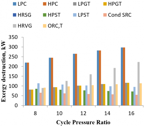
Figures 8a, 8b, and 8c show exergy destruction with cycle pressure ratio at different ambient temperatures for layout detailed in figure 1(a). For the compressor, exergy destruction is higher at higher ambient temperature, and at higher CPR here the value of maximum destruction in the compressor is 297.6 kW at 300K ambient temperature and16 CPR. For a gas turbine, the lower ambient temperature and higher CPR have higher destruction of 124.1 kW. For HRSG, higher ambient temperature and lower CPR is responsible for higher exergy destruction of 217.5 kW. For HPST, 85.69 kW of higher exergy destruction at the higher ambient temperature & lower CPR. For LPST 113.9 kW of exergy destruction occurs at higher ambient and lower CPR. For condenser 65.58 kW of exergy destruction occurs at higher ambient and lower CPR. For HRVG, the higher ambient temperature, and higher CPR is responsible for higher exergy destruction here 223 kW of exergy destruction occurs at 300 K ambient temperature and 16 CPR. ORC turbine has higher exergy destruction of 115.6 kW at lower ambient temperature and higher CPR.
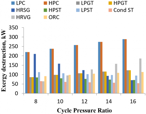
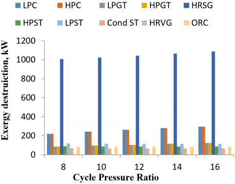
Figure 9a, 9b, and 9c show exergy destruction with cycle pressure ratio at different ambient temperatures for layout detailed in figure 1(b). For the compressor, the exergy destruction is higher at higher ambient temperature and higher CPR. Here the value of maximum destruction in the compressor is 297.6 kW at 300 K ambient temperature and 16 CPR. For a gas turbine, the lower ambient temperature and higher CPR have higher destruction of 124.1kW. For HRSG, the lower ambient temperature and higher CPR responsible for higher exergy destruction of 1090 kW. For HPST, 92.84 kW of exergy destruction is observed at the higher ambient temperature & lower CPR. For LPST, 123.3 kW of exergy destruction occurs at higher ambient and lower CPR. For condenser, 71.04 kW of exergy destruction occurs at higher ambient and lower CPR. For HRVG 27.28 kW of exergy destruction occurs at higher ambient temperature and constant with CPR. ORC turbine has higher exergy destruction of 82.09 kW at lower ambient temperature.
Figure 9a. Exergy destruction with cycle pressure ratio at 300 K ambient temperature for layout given in figure 1(b)
Figure 9b. Exergy destruction with cycle pressure ratio at 295 K ambient temperature for layout given in figure 1(b)
Figure 9c. Exergy destruction with cycle pressure ratio at 295K ambient temperature for layout given in figure 1(b)
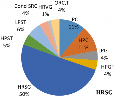
Figure 10 shows the consolidated variation of exergy destruction in different locations in the arrangements considered in the present study and graphically detailed in Figure 1(a) and Figure 1(b). These values have been plotted for the ambient temperature of 300 K and CPR of 8.
Figure 10. Exergy destruction for layouts detailed in figure 1(a)-(HRVG) and figure 1(b-(HRSG) at 300K ambient temperature and 8 CPR
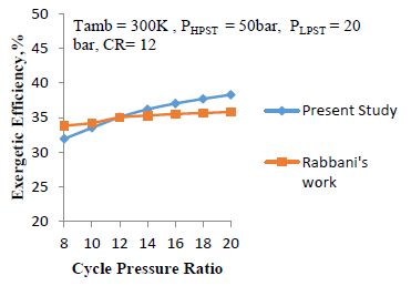
The present study’s GT-ST cycle is validated with the work of Rabbani's solarized cycle taking the same parameters of Rabbani’s study [19] as shown in Figure 11.
Figure 11. Validation of present GT-ST cycle with Rabbani’sGT-ST cycle [19]
The following conclusion has been drawn from the considered solarized triple combined cycle having intercooling, reheating, and waste heat utilization:
|
1, 2, 3….25 |
Cycle states as shown in schematic diagram |
|
a |
Molten salt inlet state to central receiver |
|
Ahf |
Heliostat Area, m2 |
|
av |
Availability |
|
b |
Molten salt outlet state from central receiver |
|
Cond |
Condenser |
|
CR |
Concentration Ratio |
|
CPR |
Cycle Pressure Ratio |
|
D |
Deaerator |
|
DSG |
Direct steam generator |
|
E |
Energy |
|
Ex |
Exergy in kJ |
|
ex |
exergy in kJ/kg |
|
Exd |
Exergy destruction |
|
Exergy_solar |
Exergy associated with solar |
|
fr |
Fraction of steam bleed |
|
Fr |
View factor |
|
G |
Generator |
|
GT |
Gas Turbine |
|
GWP |
Global warming potential |
|
h |
Enthalpy |
|
HPC |
High-Pressure compressor |
|
HPGT |
High-Pressure gas turbine |
|
HPST |
High-Pressure steam turbine |
|
HRSG |
Heat recovery steam generator |
|
HRVG |
Heat recovery vapour generator |
|
I |
Solar radiation |
|
ISCCPP |
Integrated solar combined cycle power plant |
|
LPC |
Low pressure compressor |
|
LPGT |
Low pressure gas turbine |
|
LPST |
Low pressure steam turbine |
|
m |
Mass |
|
ORC |
Organic Rankine cycle |
|
P |
Pressure |
|
p |
Pump |
|
PTC |
Parabolic trough collector |
|
Q |
Heat |
|
rec |
Receiver |
|
SRC |
Steam Rankine cycle |
|
s |
Entropy |
|
s-CO2 |
Super critical carbon di-oxide |
|
T |
Temperature |
|
turb |
Turbine |
|
ORCt |
ORC vapour turbine |
|
W |
Work |
|
$\eta$ |
Efficiency |
|
$\gamma$ |
Ratio of specific heat |
|
Subscripts |
|
|
air |
Air |
|
abs |
Heat absorbed by molten salt |
|
amb |
Ambient |
|
c |
Compressor |
|
CEP |
Condensate extraction pump |
|
Cp |
Specific heat |
|
cond. |
Condenser |
|
gt |
Gas turbine |
|
h |
Heliostat |
|
isen |
Isentropic |
|
ms |
Molten salt |
|
loss |
Heat loss in the central receiver |
|
Poly_c |
Polytropic for compressor |
|
Poly_turb |
Polytropic for turbine |
|
s |
Solar |
|
Space |
Space heating |
|
ST |
Steam turbine |
|
steam |
steam |
[1] European Commission union/2030-energy-strategy (accessed 01-05-19) https://ec.europa.eu/energy/en/topics/energy-strategy-and-energy.
[2] Ibrahim, T.K., Mohammed, M.K., Awad, O.I., Abdalla, A.N., Basrawi, F., Mohammed, M.N., Mamat, R. (2018). A comprehensive review on the exergy analysis of combined cycle power plants. Renewable and Sustainable Energy Reviews, 90: 835-850. https://doi.org/10.1016/j.rser.2018.03.072
[3] Sanjay. (2013). Exergy and energy analysis of combined cycle systems with different bottoming cycle configurations. International Journal of Energy Research, 37(8): 899-912.
[4] Chandra, H., Kaushik, S.C. (2013). Exergetic analysis of closed Brayton thermal power cycle with reheater, regenerator and intercooler. International Journal of Ambient Energy, 34(3): 122-130. https://doi.org/10.1080/01430750.2012.740426
[5] Carcasci, C., Winchler, L. (2016). Thermodynamic analysis of an Organic Rankine Cycle for waste heat recovery from an aeroderivative intercooled gas turbine. Energy Procedia, 101: 862-869. https://doi.org/10.1016/j.egypro.2016.11.109
[6] Amiralipour, M., Kouhikamali, R. (2019). Potential analysis and technical-economic optimization of conversion of steam power plant into combined water and power. Applied Thermal Engineering, 151: 191-198. https://doi.org/10.1016/j.applthermaleng.2019.02.005
[7] Idrissa, A.M., Boulama, K.G. (2019). Advanced exergy analysis of a combined Brayton/Brayton power cycle. Energy, 166: 724-737. https://doi.org/10.1016/j.energy.2018.10.117
[8] Khan, M.N., Tlili, I. (2018). Innovative thermodynamic parametric investigation of gas and steam bottoming cycles with heat exchanger and heat recovery steam generator: Energy and exergy analysis. Energy Reports, 4: 497-506. https://doi.org/10.1016/j.egyr.2018.07.007
[9] Yang, J., Sun, Z., Yu, B., Chen, J. (2018). Experimental comparison and optimization guidance of R1233zd (E) as a drop-in replacement to R245fa for organic Rankine cycle application. Applied Thermal Engineering, 141: 10-19. https://doi.org/10.1016/j.applthermaleng.2018.05.105
[10] Coco-Enríquez, L., Muñoz-Antón, J., Martinez-Val, J.M. (2017). Dual Loop line-focusing solar power plants with supercritical Brayton power cycles. International Journal of Hydrogen Energy, 42(28): 17664-17680. https://doi.org/10.1016/j.ijhydene.2016.12.128
[11] Adibhatla, S., Kaushik, S.C. (2017). Energy, exergy and economic (3E) analysis of integrated solar direct steam generation combined cycle power plant. Sustainable Energy Technologies and Assessments, 20: 88-97. https://doi.org/10.1016/j.seta.2017.01.002
[12] Rovira, A., Montes, M.J., Varela, F., Gil, M. (2013). Comparison of heat transfer fluid and direct steam generation technologies for integrated solar combined cycles. Applied Thermal Engineering, 52(2): 264-274. https://doi.org/10.1016/j.applthermaleng.2012.12.008
[13] Kelly, B., Herrmann, U., Hale, M.J. (2001). Optimization studies for integrated solar combined cycle systems. In International Solar Energy Conference, 16702: 393-398. https://doi.org/10.1115/SED2001-150
[14] Saghafifar, M., Gadalla, M. (2017). Thermo-economic optimization of hybrid solar Maisotsenko bottoming cycles using heliostat field collector: Comparative analysis. Applied Energy, 190: 686-702. https://doi.org/10.1016/j.apenergy.2016.12.165
[15] Kong, R., Deethayat, T., Asanakham, A., Vorayos, N., Kiatsiriroat, T. (2019). Thermodynamic performance analysis of a R245fa organic Rankine cycle (ORC) with different kinds of heat sources at evaporator. Case Studies in Thermal Engineering, 13: 100385. https://doi.org/10.1016/j.csite.2018.100385
[16] Bhatt, B.I., Thakore, S.B. (2008). Stoichiometry. 5th ed. McGraw Hill Publication.
[17] Shaaban, S. (2016). Analysis of an integrated solar combined cycle with steam and organic Rankine cycles as bottoming cycles. Energy Conversion and Management, 126: 1003-1012. https://doi.org/10.1016/j.enconman.2016.08.075
[18] Shahin, M.S., Orhan, M.F., Uygul, F. (2016). Thermodynamic analysis of parabolic trough and heliostat field solar collectors integrated with a Rankine cycle for cogeneration of electricity and heat. Solar Energy, 136: 183-196. https://doi.org/10.1016/j.solener.2016.06.057
[19] Rabbani, M., Ratlamwala, T.A.H., Dincer, I. (2015). Transient energy and exergy analyses of a solar based integrated system. Journal of Solar Energy Engineering, 137(1). https://doi.org/10.1115/1.4028072
[20] Hogerwaard, J., Dincer, I., Naterer, G.F. (2017). Solar energy based integrated system for power generation, refrigeration and desalination. Applied Thermal Engineering, 121: 1059-1069. https://doi.org/10.1016/j.applthermaleng.2017.03.116
[21] Deethayat, T., Kiatsiriroat, T., Thawonngamyingsakul, C. (2015). Performance analysis of an organic Rankine cycle with internal heat exchanger having zeotropic working fluid. Case Studies in Thermal Engineering, 6: 155-161. https://doi.org/10.1016/j.csite.2015.09.003
[22] Sachdeva, J., Singh, O. (2019). Thermodynamic analysis of solar powered triple combined Brayton, Rankine and organic Rankine cycle for carbon free power. Renewable Energy, 139: 765-780. https://doi.org/10.1016/j.renene.2019.02.128
[23] Choi, J.H., Ahn, J.H., Kim, T.S. (2014). Performance of a triple power generation cycle combining gas/steam turbine combined cycle and solid oxide fuel cell and the influence of carbon capture. Applied Thermal Engineering, 71(1): 301-309. https://doi.org/10.1016/j.applthermaleng.2014.07.001
[24] Li, Z., Huang, R., Lu, Y., Roskilly, A.P., Yu, X. (2019). Analysis of a combined trilateral cycle-organic Rankine cycle (TLC-ORC) system for waste heat recovery. Energy Procedia, 158: 1786-1791. https://doi.org/10.1016/j.egypro.2019.01.421
[25] Li, X., Kong, W., Wang, Z., Chang, C., Bai, F. (2010). Thermal model and thermodynamic performance of molten salt cavity receiver. Renewable energy, 35(5): 981-988. https://doi.org/10.1016/j.renene.2009.11.017