Francesco Marchione
© 2021 IIETA. This article is published by IIETA and is licensed under the CC BY 4.0 license (http://creativecommons.org/licenses/by/4.0/).
OPEN ACCESS
Adhesive bonding is experiencing a significant increase in its use in various industrial fields, thanks to the numerous advantages it offers, such as a better distribution of stresses in the resulting structure. This aspect is of importance for joints between composite substrates, which are not very resistant to concentrated stresses. The aim of this work is to present a simplified method for predicting the failure load of a single-lap adhesive joint. This theoretical model is applied to the results of an experimental study to verify the effectiveness of the adhesive bond between pultruded GFRP adherends. The results of shear tests on specimens assembled with different adhesives and subjected to different artificial ageing conditions are reported. The experimental results recorded by shear tests were processed by the simplified shear-slip model based on fracture energy. The obtained experimental results are compared with the theoretical values obtained using the analysis of the cohesive zone model theory. Then, a simple computational model is proposed for the evaluation and design of the ultimate load in single-lap adhesive joints.
energy model, fracture energy, SLJ failure mode, shear test, composites bonding
The application of composites is becoming increasingly popular in various industrial sectors thanks to their mechanical behavior, characterized by a high strength-to-weight ratio, good resistance to high temperatures and fatigue [1-3]. Due to these advantages, composites are now used for many applications such as civil engineering [4], aerospace [5] and automotive [6]. However, unlike other traditional materials, composites show a significant weakness in terms of their low strength to concentrated loads. In this context, current research developments are taking place in the field of structural adhesives [7]. Adhesive joints offer several advantages, such as more uniform stress distribution within the bonded region [8], lower weight of the resulting structure and allow different materials to be bonded together. Therefore, due to the brittle behavior of composites at classical mechanical joints (e.g. bolted joints), structural adhesives represent a viable alternative. Despite their increasing popularity in various fields, the design of adhesive joints still represents a major issue in research [9]. The design phase requires valid theoretical models to predict critical stresses and ultimate load values, so that the effectiveness of the adhesive bond can be evaluated in advance with an appropriate safety factor.
The occurrence of critical stresses and, consequently, the value of the ultimate load depends on many factors, such as the geometry of the joint and the adhesive properties, i.e. the developing adhesion between the considered joint parts and adhesive surfaces. Among the numerous joints studied in the literature, the most common type is the single-lap joint, as it is characterized by great efficiency and simplicity of assembling. However, the study of the stress distribution could be very complex.
The first analytical solutions to determine stresses in the bonded region were provided by Volkersen [10], Goland and Reissner [11] and Hart-Smith [12]. Tong [13] proposed a simple closed-form solution for predicting the ultimate load of asymmetric single-lap joints according to the global/local analysis developed by Goland and Reissner [11]. Simplified formulas for shear and joint strain energy rates in terms of longitudinal membrane forces and bending moments in adhesives were obtained. Charalambides et al. [14] used 2D FEA models to determine the failure paths and strength of single-lap joints. In their study, two material models were used for both composite adherends and adhesives. Wang and Gunnion [15] used experimental results from joining and repair tests to determine the peaks of plastic stresses caused by unbalanced distribution of shear stresses. The FE results showed good agreement with the experimental results. Pinto et al. [16] used trapezoidal cohesive laws to model the fracture mechanics within the joint and investigated the effects of repair through 3D FEA models.
Studies by Liu et al. [17] focused on different damage criteria (i.e. Hashin criterion, Yeh delamination and energy criteria) to simulate the failure occurring within composite laminates. They also developed specific CZM models to evaluate the strength of the adhesive. Alves et al. [18] studied SAJs between composite and aluminium adherends as a function of different geometrical parameters. The main objective was to develop accurate CZM models to predict the joint strength.
Several works propose a critical stress as a global failure parameter. For single-lap joints characterised by short bonding lengths, the research carried out by Crocombe [19], recommends considering the yield point of the stress-strain curve of the joint itself as the failure of the joint. Thus, reaching the plastic values of the shear stresses could be taken as the ultimate strength. Another reference for determining the failure of the joint is given by the critical energy. An example is the work of Fernlund et al. [20], in which an engineering approach to failure load prediction for adhesive joints is presented and applied. The approach assumes that the in-situ adhesive joint strength can be characterised by the critical energy release rate as a function of the loading mode for a given adhesive system. Using the J-integral for large strains together with beam theory for large strains, a simple closed-form expression for the energy release rate per area strain is obtained.
The above summarised methods consider different parameters for determining strength values for bonded joints. An effective method for predicting the failure load of the joint should be characterised by the simplicity of application, so that the designer can select the geometrical and mechanical properties of the joint without having to perform complex nonlinear analyses.
The main objective of the present work is to provide a simplified computational model to predict the failure load of a single-lap adhesive joint between pultruded GFRP adherends. In particular, an energy-theoretical model is proposed to analyse the mechanical behaviour of single-lap joints and to predict their failure load. The results of an extensive experimental campaign [21] are reported, in which single-lap adhesive joints assembled with different adhesives (i.e., epoxy, polyurethane, methacrylate and acrylate) and subjected to different artificial ageing processes (i.e., exposure to high temperature and relative humidity, exposure to UV radiation). The experimental data were used and analysed to determine the shear-slip law for the tested specimens, the experimental fracture energy and the predicted values of the joint strengths. In summary, a theoretical analysis is proposed to evaluate the value of the failure load.
This paper is divided into the following sections: first, the theoretical background on the theory of fracture according to the simplified bilinear law is presented. Then, the results of the experimental campaign are reported and the theory is applied and compared with the experimental data, to demonstrate the accuracy of the theory in predicting the failure load of the tested bonded joints.
The identification and therefore the prediction, of the failure load of the adhesive joint depends on the determination of the fracture energy Gf of the joint under consideration. This value depends on the mechanical and physical properties of the adhesives considered. In fact, the fracture energy is determined by evaluating the shear stress-slip law of the interface between the adherends. In the following section, an analytical solution for the prediction of the failure load is presented considering a simplified bilinear model. This analytical solution provides a theoretical analysis for the investigation and evaluation of the experimental campaign on adhesive joints between GFRP pultruded profiles.
2.1 Theoretical analysis of a single-lap joint
Figure 1 shows the scheme of a shear test of a single-lap joint between adherends in GFRP pultruded profiles. The width, thickness and Young's modulus of the GFRP adherends are indicated by$b_{i}, t_{i}$ ed $E_{i}$, (i=1, 2) and for the adhesive by $b_{a}, t_{a}$ ed $E_{a}$. The bond length between the pultruded profiles is L.
The following assumptions are made:
Considering the equilibrium of the infinitesimal element shown in Figure 1, the following equation could be obtained:
$\frac{d \sigma_{1}(x)}{d x}=\frac{\tau(x)}{t_{1}}$ (1)
where, $\tau(x)$ represents the shear stress in the adhesive layer and $\sigma_{1}(x)$ represents the axial stress in the adherends.
Figure 1. Deformation and stresses in the adhesive joint
The constitutive equations for the adhesive and the adhesives are given by:
$\tau(x)=f(\delta)$ (2)
$\sigma_{1}(x)=E_{1} \frac{d u_{1}(x)}{d x}$ (3)
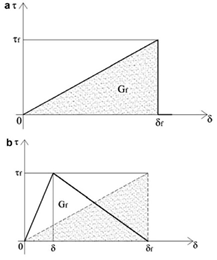
Figure 2. Simplified linear (a) and bilinear t-δ law (b)
The simplified model adopted to describe the shear stress-slip relationship, s-d, is represented by the well-known curve shown in Figure 2, usually used to model the CZM cohesive zone model in FEA analyses.
The stress-strain graph (Figure 2a) shows an increasing linear behaviour until the crisis occurs (i.e. fracture initiation), i.e. until the maximum shear stress is reached, beyond which the curve drops to zero, according to a brittle trend with no change in overall stiffness:
$f(\delta)=\left\{\begin{array}{c}\frac{\tau_{f}^{2}}{2 G_{f}} \delta \text { for } 0 \leq \delta \leq \delta_{f} \\ 0 \text { for } \delta>\delta_{f}\end{array}\right.$ (4)
where, $G_{f}$ is the fracture energy, the energy required to bring a local bond element to shear fracture. The analytical expression of the fracture energy is given by the following equation:
$G_{f}=\frac{1}{2} \delta_{f} \tau_{f}$ (5)
Substituting Eqns. (2), (3) and (4) into Eq. (1) the following – valid as far as $\delta \leq \delta_{f}$ - is obtained:
$\frac{d^{2} u_{1}(x)}{d x^{2}}-\lambda_{1}^{2} u_{1}(x)=0$ (6)
where:
$\lambda_{1}^{2}=\frac{\tau_{f}^{2}}{2 t_{1} E_{1} G_{f}}$ (7)
With the following boundary conditions:
$\sigma_{1}=0$ at $x=0$; $\sigma_{1}=\frac{P}{b_{1} t_{1}}$ at $x=L$ (8)
Eq. (6) could be solved, obtaining the expression of relative displacement, shear stress in the adhesive and normal stress in the adhesives in GFRP:
$\delta=u_{1}(x)-u_{2}(x)=A \cosh (\lambda x)+B \sinh (\lambda x)$ (9)
$\tau(x)=\frac{\tau_{f}^{2}}{2 G_{f}}[A \cosh (\lambda x)+B \sinh (\lambda x)]$ (10)
$\sigma_{1}(x)=\frac{\tau_{f}^{2}}{2 G_{f} \lambda t_{1}}\left[A \cosh (\lambda x)+B \sinh (\lambda x)+\frac{P}{b_{2} E_{2} \lambda t_{2}}\right]$ (11)
Constants A, B could be determined using boundary conditions.
In the specific case, where the adherends have the same mechanical and geometrical characteristics, it is easily verified that $E_{1}=E_{2}=E ; b_{1}=b_{2}=b ; t_{1}=t_{2}=t$.
Therefore, constants A, B are expressed by the following equations:
$A=\frac{P}{\lambda b E t}\left(\frac{1}{\tanh (\lambda L)}+\frac{1}{\sinh (\lambda L)}\right)$ (12)
$B=-\frac{P}{\lambda b E t}$ (13)
It is possible to express displacement values from Eq. (9):
$\delta=\frac{P}{\lambda} \frac{\cosh (\lambda L)+1}{b E t \sinh (\lambda L)}$ (14)
By placing the value of the displacement obtained in Eq. (14) equal to the ultimate displacement $\delta_{f}$, it is possible to obtain the value of the ultimate load (i.e. the ultimate strength of the joint):
$P_{\max }=\lambda \delta_{f} b E t \tanh \left(\frac{\lambda L}{2}\right)$ (15)
This section reports the results obtained from an extensive experimental campaign [21] on single-lap joints between GFRP pultruded adherends and different types of adhesives (i.e. epoxy, polyurethane, acrylic and methacrylate), both after curing in a laboratory environment and after artificial ageing.
3.1 Material properties
3.1.1 Adherends
The adherends used in the experimental campaign consist of pultruded GFRP profiles, supplied by Fibrolux, Germany. In order to determine the mechanical properties, the GFRP laminates were tested in tension. The width of the profiles was 25 mm, the thickness 5 mm and the length 100 mm. The tests were performed on a Zwick/Roell Z050 automatic tensile machine, measuring the strain with a strain gauge and using a speed ratio of 5 mm/min. The results of the tensile tests are shown in Table 1.
Table 1. GFRP mechanical properties
|
Artificial exposure |
Et (GPa) |
σt (MPa) |
εt (%) |
|
T0 |
29.80 ± 2.60 |
168.80 ± 31.10 |
0.70 ± 0.20 |
|
TC |
27.10 ± 2.60 |
251.80 ± 61.90 |
0.90 ± 0.20 |
|
TUV |
27.80 ± 6.50 |
199.40 ± 91.60 |
0.80 ± 0.30 |
3.1.2 Adhesives
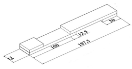
Six different adhesives in the present experimental campaign were used: two epoxy adhesives (EPX1, EPX2), one acrylic (ACR), one methacrylate (MET) and two polyurethane (PU and MS). Table 2 shows the mechanical properties, as reported by the manufacturers. In order to determine the missing mechanical properties, dogbone test specimens were made for tensile testing. The dimensions of the dogbone test specimens are shown in Figure 3. The results obtained are shown in Table 3.
3.1.3 Experimental setup
The shear tests carried out detect the load-displacement curves of the joint using a tensile machine, as specified by ISO 4587 [22]. The tensile machine is of the Zwick/Roell Z050 electromechanical type. The tests were performed under laboratory conditions, with an average temperature of 24℃ and a relative humidity of 50%. All tests are performed at a speed rate of 1.27 mm/min. An optical measurement technique based on stereoscopic calculation using a geometric grid was used to record the displacement values. Two CMOS cameras with a resolution of 1280 × 1024 pixels were installed at different angles to acquire stereoscopic images at a regular rate of 2 frames/second.
Figure 3. Dogbones’ geometry (measures in mm)
Table 2. Technical and mechanical characteristics of the adhesives reported by manufacturers
|
Adhesive |
EPX 1 |
EPX 2 |
ACR |
MET |
PU |
MS |
|
τ (MPa) |
33.5* |
15* |
25 |
15-30 |
2.60 |
1.80 |
|
σt (MPa) |
- |
17 |
- |
12-22 |
6 |
- |
|
Et (MPa) |
- |
1700 |
- |
- |
- |
- |
|
εt **(%) |
3 |
5 |
5 |
<10 |
>100 |
>100 |
Table 3. Mechanical properties of adhesives dogbones
|
Series |
Et (MPa) |
σt (MPa) |
εt (%) |
|
EPX 1 |
2966.39 ± 44.12 |
27.34 ± 0.77 |
2.39 ± 0.65 |
|
EPX 2 |
1774.03 ± 30.28 |
17.11 ± 0.70 |
3.81 ± 0.23 |
|
ACR |
648.60 ± 22.00 |
11.13 ± 0.50 |
7.26 ± 0.70 |
|
MET |
428.66 ± 62.00 |
7.31 ± 0.42 |
2.96 ± 0.05 |
|
PU |
2.43 ± 0.14 |
3.41 ± 0.27 |
150.79 ± 15.93 |
|
MS |
2.05 ± 0.18 |
2.03 ± 0.10 |
151.10 7.24 |
3.2 Specimens geometry
The specimens were assembled according to the geometrical indications illustrated by ASTM D638:2014 [23]; for each configuration indicated above, three specimens were tested. The size of the GFRP adherends was 25 mm × 100 mm, with a thickness of 5 mm. The same adhesive thickness of 0.30 mm was used for EPX1, EPX2, ACR and MET adhesives. For PU and MS adhesives 2.00 mm thickness was used, according to manufacturer’s recommendations. Specimen geometry is shown in Figure 4.
Figure 4. Single-lap specimen geometry (measures in mm)
Before the bonding phase, all bonding surfaces were cleaned with denatured isopropyl alcohol. For the adhesives used, the timescales for their complete polymerization were met. All specimens were cured under laboratory conditions for a period of 28 days.
3.3 Artificial ageing
Two different artificial ageing modes were considered in the reported experimental campaign: exposure to high temperature and relative humidity (Tc) and exposure to UV radiation (Tuv). The first ageing mode was simulated using an “Angelantoni” CST-130 S type climatic chamber. Each cycle consisted of three exposure periods: first 16 hours at a constant temperature of 40°C and relative humidity of 100%, then 4 hours at a constant temperature of 40℃ and finally 4 hours at a constant temperature of 70℃ and RH of 50%. This ageing cycle was repeated for 2 weeks, according to the standard [24].
Exposure to UV radiation was simulated using eight UV fluorescent lamps (Philips Actinic BL TL-D). Specimens were subjected to UV radiation under laboratory conditions (21℃, RH 33%). The wavelength of the lamps is within the range of 340 to 400 nm, with a peak at 370 nm producing a UV irradiation of 41 to 45 W/m2 on the surfaces of the samples. The 24-hour cycle was repeated 42 times without interruption.
4.1 Shear tests on single-lap adhesive joints
This section presents and analyses the load-displacement graphs and failure modes of the tested specimens [21].
4.1.1 Mechanical performance
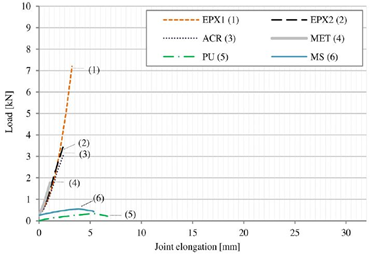
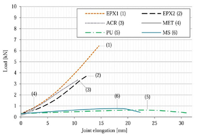
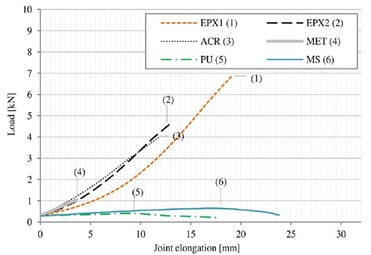
Figure 5(a-b-c) show the load-elongation curves obtained from shear tests on GFRP-GFRP single lap adhesive joints, according to T0, TC and TUV aging conditions, respectively.
(a)
(b)
(c)
Figure 5. Load-elongation graphs [21] for unaged single-lap specimens in laboratory conditions (a); aged in climatic chamber (b) and exposed to UV radiations (c)
Table 4 shows the average results obtained from the experimental campaign, according to T0, TC and TUV aging conditions, respectively.
Comparing the results obtained, EPX1 adhesive exhibits the best mechanical performance for every environmental conditions. Higher elongations were generally observed, especially after exposure to UV radiation. EPX2 samples achieved lower ultimate loads than EPX1, but higher than other structural adhesives. The joint elongations are lower than with the previous epoxy adhesive (about 14 mm for the samples subjected to UV radiation). The effectiveness of the adhesive joint is negatively affected by exposure to high temperatures and relative humidity, especially for epoxy adhesives, where the failure modes changed from cohesive to mainly adhesive. The non-structural adhesives (PU and MS) showed similar or similar load-bearing capacity, with little difference between unaged and aged conditions. The MS adhesive exhibited better performance than PU.
Table 4. Mechanical properties [21] of GFRP-GFRP single-lap joints under different environmental aging conditions
|
Adhesive |
Aging condition |
Fmax (kN) |
L* (mm) |
τmax* (MPa) |
k* (kN/mm) |
|
EPX 1 |
T0 |
7.20 ± 0.50 |
3.20 ± 0.40 |
24.60 |
1.15 |
|
TC |
6.30 ± 1.20 |
14.60 ± 3.00 |
20.60 |
0.34 |
|
|
TUV |
6.90 ± 0.40 |
19.20 ± 2.10 |
22.10 |
0.18 |
|
|
EPX 2 |
T0 |
3.50 ± 0.80 |
2.30 ± 0.70 |
11.10 |
1.32 |
|
TC |
3.80 ± 0.20 |
12.50 ± 0.50 |
12.00 |
0.23 |
|
|
TUV |
4.70 ± 0.10 |
13.20 ± 1.40 |
15.10 |
0.28 |
|
|
ACR |
T0 |
3.10 ± 0.70 |
2.40 ± 0.60 |
10.00 |
1.11 |
|
TC |
3.40 ± 1.00 |
10.80 ± 3.40 |
10.90 |
0.31 |
|
|
TUV |
4.00 ± 0.40 |
11.90 ± 3.80 |
12.90 |
0.35 |
|
|
MET |
T0 |
1.80 ± 0.10 |
1.10 ± 0.04 |
5.70 |
1.64 |
|
TC |
0.70 ± 0.20 |
2.50 ± 0.70 |
2.30 |
0.39 |
|
|
TUV |
1.10 ± 0.20 |
3.70 ± 1.30 |
3.40 |
0.30 |
|
|
PU |
T0 |
0.30 ± 0.04 |
0.60 ± 0.20 |
3.90 |
1.98 |
|
TC |
0.60 ± 0.02 |
22.40 ± 9.80 |
2.00 |
0.04 |
|
|
TUV |
0.40 ± 0.04 |
9.40 ± 3.00 |
1.30 |
0.11 |
|
|
MS |
T0 |
0.50 ± 0.10 |
4.00 ± 0.50 |
1.80 |
0.26 |
|
TC |
0.80 ± 0.04 |
117.60 ± 1.30 |
2.50 |
0.06 |
|
|
TUV |
0.60 ± 0.10 |
17.90 ± 2.90 |
2.10 |
0.07 |
Table 5. Comparison of experimental results with theoretical data
|
Adhesive |
Aging condition |
Pexp (N) |
$\boldsymbol{\delta}_{\boldsymbol{f}, \boldsymbol{e x p}}$ (mm) |
τf,exp* (MPa) |
$\boldsymbol{G}_{\boldsymbol{f}, \boldsymbol{e x p}}$ (kN/mm) |
Theoretical load Pmaz (N) |
ΔP (%) |
|
EPX 1 |
T0 |
7200 |
3.20 |
24.60 |
1.15 |
7326.11 |
+ 1.7515 |
|
TC |
6300 |
14.60 |
20.60 |
0.34 |
6402.63 |
+ 1.6290 |
|
|
TUV |
6900 |
19.20 |
22.10 |
0.18 |
7012.07 |
+ 1.6242 |
|
|
EPX 2 |
T0 |
3500 |
2.30 |
11.10 |
1.32 |
3559.59 |
+ 1.7026 |
|
TC |
3800 |
12.50 |
12.00 |
0.23 |
3861.58 |
+ 1.6205 |
|
|
TUV |
4700 |
13.20 |
15.10 |
0.28 |
4776.33 |
+ 1.6240 |
|
|
ACR |
T0 |
3100 |
2.40 |
10.00 |
1.11 |
3152.29 |
+ 1.6868 |
|
TC |
3400 |
10.80 |
10.90 |
0.31 |
3455.12 |
+ 1.6212 |
|
|
TUV |
4000 |
11.90 |
12.90 |
0.35 |
4064.90 |
+ 1.6225 |
|
|
MET |
T0 |
1800 |
1.10 |
5.70 |
1.64 |
1830.78 |
+ 1.7100 |
|
TC |
700 |
2.50 |
2.30 |
0.39 |
711.33 |
+ 1.6186 |
|
|
TUV |
1100 |
3.70 |
3.40 |
0.30 |
1117.82 |
+ 1.6200 |
|
|
PU |
T0 |
300 |
0.60 |
3.90 |
1.98 |
304.81 |
+ 1.6033 |
|
TC |
600 |
22.40 |
2.00 |
0.04 |
609.61 |
+ 1.6017 |
|
|
TUV |
400 |
9.40 |
1.30 |
0.11 |
406.41 |
+ 1.6025 |
|
|
MS |
T0 |
500 |
4.00 |
1.80 |
0.26 |
508.04 |
+ 1.6080 |
|
TC |
800 |
117.60 |
2.50 |
0.06 |
812.80 |
+ 1.6000 |
|
|
TUV |
600 |
17.90 |
2.10 |
0.07 |
609.61 |
+ 1.6017 |
This section reports the results obtained by the analytical analysis previously presented. The results obtained from the experimental campaign allowed the evaluation of the values of the fracture energy, shear stresses in the adhesive and the ultimate displacement.
Table 5 summarises the results obtained from the experimental campaign described above. In particular, the experimental values of the ultimate load, displacement, maximum shear stress and fracture energy, obtained by Eq. (5), are given here. The value of the ultimate load obtained from the theoretical analysis (Eq. (15)) is calculated. A good agreement is observed between the load value predicted by the theoretical analysis and the experimental one (variation of the results contained within 2%). In this sense, it is possible to obtain the experimental value of the fracture energy for different combinations of adhesives. Once this value is known, it is possible to predict the value of the failure load for different geometrical layouts of the adhesive surface. The results obtained show the applicability of the above theory for the design of adhesive joints.
The shear behavior of single lap adhesive joints between pultruded GFRP adherends is investigated both experimentally, by evaluating the data from the experimental campaign reported in Ref. [21], and theoretically, using the fracture mechanics analysis. The results obtained from the experimental campaign are the following:
This paper presents a practical method for evaluating the ultimate load in single-lap joints between adhesives in GFRP pultruded profiles. The experimental data allow the evaluation of the ultimate load and displacement, and consequently of the fracture energy Gf. Through the cohesive zone theory and, in particular, through the push-push joint model, it is possible to determine the value of the ultimate load to a good approximation. Future developments of the present research will deepen the comparison of the above model with further combinations of adherends and adhesives, and will verify the application of the above theoretical model to different types of stresses (e.g. dynamic regime) and artificial ageing of bonded joints.
|
bi |
width of the adherend |
|
ti |
thickness of the adherend |
|
Et |
Young Modulus in tension |
|
Pmax |
maximum theoretical/exp. load |
|
ACR |
acrylic adhesive |
|
At |
Application temperature |
|
EPX1 |
First Epoxy Adhesive |
|
EPX2 |
Second Epoxy Adhesive |
|
GFRP |
Glass-fiber-reinforced polymer |
|
k |
Stiffness |
|
L |
Joint elongation |
|
MET |
methacrylate adhesive |
|
MF |
Mixed failure |
|
MS |
Second polyurethane adhesive |
|
PU |
First polyurethane adhesive |
|
St |
Service temperature |
|
T0 |
Unaged conditions |
|
TC |
Artificial aging in climatic chamber |
|
TUV |
Artificial aging under UV rays |
|
Wt |
Working time at 22℃ |
|
Greek symbols |
|
|
$\sigma_{t}$ |
axial strenght |
|
$\alpha$ |
Thermal coefficient of expansion |
|
$\varepsilon_{\mathrm{t}}$ |
Tensile strain |
|
$\sigma_{t}$ |
Tensile strenght |
|
$\tau$ |
Shear stress |
|
$\gamma$ |
Shear strain at failure |
[1] Wu, C., Bai, Y. (2014). Web crippling behaviour of pultruded glass fibre reinforced polymer sections. Composite Structures, 108: 789-800. https://doi.org/10.1016/j.compstruct.2013.10.020
[2] Wu, C., Bai, Y., Zhao, X.L. (2015). Improved bearing capacities of pultruded glass fibre reinforced polymer square hollow sections strengthened by thin-walled steel or CFRP. Thin-Walled Structures, 89: 67-75. https://doi.org/10.1016/j.tws.2014.12.006
[3] de Castro, J., Keller, T. (2008). Ductile double-lap joints from brittle GFRP laminates and ductile adhesives, Part II: numerical investigation and joint strength prediction. Composites Part B: Engineering, 39(2): 282-291. https://doi.org/10.1016/j.compositesb.2007.02.016
[4] Balamuralikrishnan, R., Saravanan, J. (2019). Finite element analysis of beam–column joints reinforced with GFRP reinforcements. Civil Engineering Journal, 5(12): 2708-2726. https://doi.org/10.28991/cej-2019-03091443
[5] Vogelesang, L.B., Vlot, A. (2000). Development of fibre metal laminates for advanced aerospace structures. Journal of Materials Processing Technology, 103(1): 1-5. https://doi.org/10.1016/S0924-0136(00)00411-8
[6] Machado, J.J.M., Nunes, P.D.P., Marques, E.A.S., da Silva, L.F. (2019). Adhesive joints using aluminium and CFRP substrates tested at low and high temperatures under quasi-static and impact conditions for the automotive industry. Composites Part B: Engineering, 158: 102-116. https://doi.org/10.1016/j.compositesb.2018.09.067
[7] Marchione, F. (2020). Investigation of vibration modes of double-lap adhesive joints: Effect of slot. International Journal of Engineering, 33(10): 1917-1923. https://doi.org/10.5829/ije.2020.33.10a.10
[8] Marchione, F. (2021). Stress distribution in double-lap adhesive joints: Effect of adherend reinforcement layer. International Journal of Adhesion and Adhesives, 105: 102780. https://doi.org/10.1016/j.ijadhadh.2020.102780
[9] Alderucci, T., Rossi, M., Chiappini, G., Munafò, P. (2019). Effect of different aging conditions on the shear performance of joints made between GFRP and glass with a UV absorbance coating. International Journal of Adhesion and Adhesives, 94: 76-83. https://doi.org/10.1016/j.ijadhadh.2019.05.009
[10] Volkersen, O. (1938). Die nietkraftverteilung in zugbeanspruchten nietverbindungen mit konstanten laschenquerschnitten. Luftfahrtfor schung, 15: 41-47.
[11] Goland, M., Reissner, E. (1944). The stresses in cemented joints. J Appl Mech, 66: A17.
[12] Hart-Smith, L.J. (1973). Adhesive-bonded scarf and stepped-lap joints.
[13] Tong, L. (1998). Strength of adhesively bonded single-lap and lap-shear joints. International Journal of Solids and Structures, 35(20): 2601-2616. https://doi.org/10.1016/S0020-7683(97)00174-1
[14] Charalambides, M.N., Kinloch, A.J., Matthews, F.L. (1998). Adhesively-bonded repairs to fibre-composite materials II. Finite element modelling. Composites Part A: Applied Science and Manufacturing, 29(11): 1383-1396. https://doi.org/10.1016/S1359-835X(98)00061-X
[15] Wang, C.H., Gunnion, A.J. (2008). On the design methodology of scarf repairs to composite laminates. Composites Science and Technology, 68(1): 35-46. https://doi.org/10.1016/j.compscitech.2007.05.045
[16] Pinto, A.M.G., Campilho, R.D.S.G., De Moura, M.F.S.F., Mendes, I.R. (2010). Numerical evaluation of three-dimensional scarf repairs in carbon-epoxy structures. International Journal of Adhesion and Adhesives, 30(5): 329-337. https://doi.org/10.1016/j.ijadhadh.2009.11.001
[17] Liu, B., Xu, F., Feng, W., Yan, R., Xie, W. (2016). Experiment and design methods of composite scarf repair for primary-load bearing structures. Composites Part A: Applied Science and Manufacturing, 88: 27-38. https://doi.org/10.1016/j.compositesa.2016.05.011
[18] Alves, D.L., Campilho, R.D.S.G., Moreira, R.D.F., Silva, F.J.G., Da Silva, L.F.M. (2018). Experimental and numerical analysis of hybrid adhesively-bonded scarf joints. International Journal of Adhesion and Adhesives, 83: 87-95. https://doi.org/10.1016/j.ijadhadh.2018.05.011
[19] Crocombe, A.D. (1989). Global yielding as a failure criterion for bonded joints. International Journal of Adhesion and Adhesives, 9(3): 145-153. https://doi.org/10.1016/0143-7496(89)90110-3
[20] Fernlund, G., Papini, M., McCammond, D., Spelt, J.K. (1994). Fracture load predictions for adhesive joints. Composites Science and Technology, 51(4): 587-600. https://doi.org/10.1016/0266-3538(94)90091-4
[21] Stazi, F., Giampaoli, M., Rossi, M., Munafò, P. (2015). Environmental ageing on GFRP pultruded joints: comparison between different adhesives. Composite Structures, 133: 404-414. https://doi.org/10.1016/j.compstruct.2015.07.067
[22] Japanese Industrial Standards Committee. (1999). Determination of tensile lap-shear strength of rigid-to-rigid bonded assemblies. JIS K 6850.
[23] American Society for Testing and Materials. (2010). Standard test method for tensile properties of plastics. American Society for Testing and Materials.
[24] ISO 6270-2:2017 Paints and varnishes — Determination of resistance to humidity — Part 2: Condensation (in-cabinet exposure with heated water reservoir.