Sagar Swami | Rahul Kumar | Neetesh Kumar
OPEN ACCESS
Solar energy is a revolutionary technology which can offer tremendous long-standing benefits. Solar cells turn the solar power into electric power. Solar tracing device is the most effective technology for improving productivity and performance by using the solar cell to optimize solar energy. In the production of hardware, we use LDR's as photo sensors and two servomotors to guide the solar panel location. The software part is employed by Arduino Nano with code written in “C language”.
solar tracking system, LDR, servomotor, Arduino Nano, microcontroller
A Solar Tracker is a tool used to guide a solar panel to the sun by means of the light sensing devices attached to the system by means of a motor, as the location of the sun changes during the day, therefore achieving maximum solar radiation on the solar panel. A solar tracker's main goal is to turn the solar panel in the direction of the sun's movement because solar panel must be perpendicular to the sun to generate maximum amount of energy. This is designed to ensure that the solar panel still receives the full amount of solar energy. All monitoring systems possess one or two degrees of freedom depending on the number of rotation axes. Solar trackers are divided into two groups on this basis: single axis and Dual axis solar tracker [1].
A. Types of solar trackers
Single Axis Solar Tracker-Horizontal or vertical, it will rotate in only one plane. Despite the less complex design, it is also less effective in collecting the total solar energy. Trackers with single axes are not as productive as trackers with double shafts.
Dual axis solar tracker-It has two degrees of movement, which function as rotation shafts. Normally, those shafts are regular to one another. The shaft fixed in relation to the base can be regarded as a primary axis. A secondary axis can be considered the axis which is referenced to the primary shaft. It can rotate in horizontal and vertical plane simultaneously, and can always point to the sun. Because of this dual movement this system is highly productive in terms of efficiency. This system tracks the sun for extra power output and ease, both Left(west) to Right(east) and Up (North) and Down (South) [2].
A. Working and block diagram
The Arduino [3] is in control for all the logical operation that the device needs to do as intended. The Arduino is equipped with a 7- or 9-Volt battery, analog output from LDR’s is given to analog pins of Arduino (A0, A1, A2, A3) [4]. The Arduino analyses the signals received from the LDRs according to the direction of the sun. The resistance and, thus, the values of the current flowing into the Arduino can differentiate depending on which of the LDRs has additional light incident on it. Then, this difference is converted into analog values and send to the motor input signals. The servomotors, which are attached to the panel, are responsible for the panel's dual-axis motion. This causes the panel pane to rotate in the direction of the LDR offering the minimum resistance and thus guarantees that the light falls on panel is maximum, and convert light energy to electrical energy.
Figure 1. The whole design block diagram to incorporate an Active Dual Axis Solar Tracker
B. Software program writing of the Arduino Nano
Algorithm –
Step 1: Start, give power supply to Arduino, Servomotor, Potential Divider Circuit.
Step 2: Set all necessary data to default conditions.
Step 3: Assign analog output from potential divider circuit to Arduino.
Step 4: Comparison of input analog voltages by Arduino by using two conditions-
I. It compares the voltage of top LDR with the voltage of down LDR. And if there is difference between these two voltages more than a threshold voltage, then the digital signal in the form of PWM was given to vertical movement servomotor which moves the solar plate upward or downward as per requirement.
II. Similarly, it compares the voltage of left LDR with the voltage of the right LDR. And if there is difference between these two voltages more than a threshold voltage, then the digital signal in the form of PWM was given to horizontal movement servomotor which moves the solar plate leftward or rightward as per requirement.
Step 5: Repeat step 4 after fixed time.
Step 6: End.
C. Hardware implementation of dual axis solar tracking system
The Dual Axis Solar Tracker consists of the solar panel, four LDR sensors, two servomotors, and the Arduino Nano board.
1. Solar Panel- Solar panels are gear’s that convert the solar energy into DC electrical energy. The PV panel used in this setup is capable of producing 0.3 W of power, and it generates a voltage of 8 V.
2. Light Dependent Resistor- LDR is a passive transducer so we can use the potential divider circuit to get the corresponding voltage value from the LDR [5] resistance. The resistance of LDR is inversely proportional to the light intensity falling on it i.e., Greater light intensity or visibility the lower the resistance and vice versa.
3. Servomotor- Actually, the servo motor is an array of four things: a standard DC motor, a gear reduction mechanism, a position-sensor and a control panel. The purpose of the servo is to receive a control signal that represents the desired output position of the servo shaft and to apply the power to its DC motor until the shaft is moved to that position. The position-sensing tool is used to determine the shaft's rotational orientation, so it knows how the motor will turn to move the shaft to the ordered location. The servomotor has a connection with 3 wires: power, ground, and control.
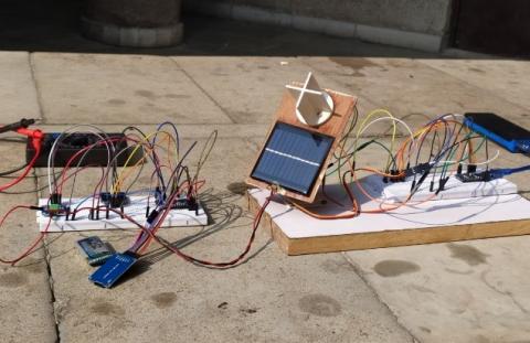
Figure 2. Final experimental setup
4. Arduino Nano- The Arduino Nano board can be powered via a USB connection or with an external DC power supply. It has 14 digital input/output pins (of which 6 can be used as PWM outputs) and 6 analog inputs. The four LDR sensors are connected to Arduino analog pins A0 to A3 that act as inputs of the system and the two servo motors are connected to D9 and D10.
|
Time |
Fixed Panel Voltage |
Dual Axis Voltage |
|
10hrs |
4.0 |
5.3 |
|
11hrs |
4.5 |
5.8 |
|
12hrs |
5.2 |
6.0 |
|
13hrs |
5.9 |
6.3 |
|
14hrs |
6.3 |
6.5 |
|
15hrs |
5.6 |
5.8 |
|
16hrs |
4.4 |
5.2 |
|
|
Average = 5.1 |
Average = 5.8 |
Figure 3. Graphical comparison of fixed panel and dual axis
With the aid of microcontrollers [6] and LDR sensors, this project provided a means of monitoring the sun's location. Specifically, it demonstrates a working software solution to optimize the efficiency of solar cells by placing a solar panel at the highest light intensity level. In addition, the tracker can initialize the starting position itself which eliminates the need for additional photo resistors. The developed solar tracker’s [7] attractive feature is simple mechanism for control of the device. Through our evaluation we found that the dual axis tracker can extract 13 per cent more power than the fixed panel.
[1] Ghosh, S., Haldar, N. (2014). Solar tracking system using AT89C51 microcontroller and LDR. International Journal of Emerging Technology and Advanced Engineering, 4(12).
[2] Kamble, S., Chavan, V. (2015). Dual Axis Solar Tracker System. International Journal of Engineering and Technology.
[3] Arduino: http://www.arduino.cc.
[4] Servomotor Database: http://www.servoda tabase.com.
[5] Akbar, H.S., Siddiq, A.I., Aziz, M.W. (2017). Microcontroller based dual axis sun tracking system for maximum solar energy generation. American Journal of Energy Research, 5(1): 23-27.
[6] Pradeep, K.P.J., Reddy, K.S.P., Mouli, C.C., Raju, K.N. (2014). Development of dual-axis solar tracking using arduino with lab view. International Journal of Engineering Trends and Technology, 17(7): 321-324.
[7] Solar tracker definition: http://http://en.wikipedia.org/wiki/Solar_tracker.